US4505231A - Water heater construction with sediment removal means - Google Patents
Water heater construction with sediment removal means Download PDFInfo
- Publication number
- US4505231A US4505231A US06/589,948 US58994884A US4505231A US 4505231 A US4505231 A US 4505231A US 58994884 A US58994884 A US 58994884A US 4505231 A US4505231 A US 4505231A
- Authority
- US
- United States
- Prior art keywords
- water
- tank
- tank means
- curved portion
- streams
- Prior art date
- Legal status (The legal status is an assumption and is not a legal conclusion. Google has not performed a legal analysis and makes no representation as to the accuracy of the status listed.)
- Expired - Lifetime
Links
Images

Classifications
-
- F—MECHANICAL ENGINEERING; LIGHTING; HEATING; WEAPONS; BLASTING
- F24—HEATING; RANGES; VENTILATING
- F24H—FLUID HEATERS, e.g. WATER OR AIR HEATERS, HAVING HEAT-GENERATING MEANS, e.g. HEAT PUMPS, IN GENERAL
- F24H9/00—Details
- F24H9/0005—Details for water heaters
- F24H9/0042—Cleaning arrangements
Definitions
- This invention relates to a water heater construction having a means for preventing the accumulation of solid particles in the bottom portion of the water heater.
- the water heater construction of the present invention is designed particularly for use in residential-type water heaters, i.e., water heaters of a smaller size than commercial water heaters.
- a water heater including a water tight tank and a source of heat for heating water inside the tank and a hot water outlet located in the top of the tank.
- a tubular agitator means is mounted in the tank, which includes a straight vertical portion, a first curved portion lying in a substantially vertical plane and a second curved portion lying in a substantially horizontal plane adjacent the bottom of the tank.
- the straight vertical portion extends through the top of the tank and is adapted for connection to a source of water under pressure.
- the second curved portion has a plurality of openings therein through which streams of water will be directed into the tank each time water is drawn out of the top of the tank. Such streams of water are directed in the same general direction as the water flowing through the tube itself to thereby produce a swirling action in the bottom portion of the tank, which swirling action is effective to prevent accumulation of sediment in the tank.
- FIG. 1 is a side elevation view of a water heater with parts broken away which incorporates the inlet tube construction of the present invention
- FIG. 2 is a side elevation view of the inlet tube shown in FIG. 1;
- FIG. 3 is a top plan view of the inlet tube shown in FIG. 2;
- FIG. 4 is a bottom plan view of the inlet tube shown in FIG. 2;
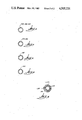
- FIGS. 5-8 are sectional views taken along lines 5--5, 6--6, 7--7 and 8--8 of FIG. 4;
- FIG. 9 is a cross-sectional view taken along line 9--9 of FIG. 2.
- FIG. 1 shows the water heater of the present invention, which is comprised of a tank wall 10, a top head member 12, and a bottom head member 14. Top and bottom head members 12 and 14 are sealed to the tank wall 10 by any suitable means such as welding to form a liquid-tight tank having a water heating chamber 15 therein.
- the tank wall 10 is covered by a layer of insulation 16 and a jacket 18.
- a combustion chamber 19 is located beneath bottom head member 14 in which a burner 21 of any suitable design is mounted.
- the products of combustion pass upwardly through a centrally located flue tube 20 connected to bottom head 14.
- Flue tube 20 extends upwardly through an opening in top head 12 and is vented to atmosphere by a suitable vent means (not shown).
- An inlet agitator tube means 22 is mounted in chamber 15 of the water heater.
- the water heater shown in FIG. 1 is a typical gas-fired residential water heater. It should be understood that the inlet tube 22 of the present invention can be used in other types of water heaters, namely, electric residential water heaters and gas and electric commercial water heaters.
- the inlet tube 22 is comprised of a straight vertical portion 24, a first curved portion 26 lying in a substantially vertical plane and a second curved portion 28 lying in a substantially horizontal plane.
- a sleeve member 30 is mounted on the upper end of vertical portion 24 of inlet tube 22. The detailed construction and function of sleeve member 30 will be described hereinafter.
- An outlet fitting 31 of any suitable design is mounted in the top head member 12.
- the first curved tube portion 26 curves for approximately 90° from the vertical to thus locate second curved portion 28 in a substantially horizontal plane.
- curved portion 28 curves approximately 180° and terminates in a short straight portion 32.
- the end of portion 32 is closed as indicated by reference numeral 34.
- the inlet tube 22 is made from stainless steel material.
- first curved portion 22 is provided with openings 36, 38.
- Second curved portion 28 is provided with openings 40, 42 and 44.
- Straight portion 32 is provided with an opening 48.
- An opening 46 is located at the junction between curved portion 28 and straight portion 32.
- All of the openings identified above are located so that the water flowing therefrom will be directed downwardly at an angle with respect to the horizontal plane A (FIG. 2) in which curved tube portion 28 lies.
- FIGS. 5-8 show the position of the openings in the tube relative to a vertical plane passing through the axis of the tube at the location of each opening. Openings 36, 40, 46 are in the vertical plane. Openings 38, 42, 44, 48 are at an angle with respect to the vertical plane.
- the dotted arrows in FIG. 4 represent the approximate direction of flow out of each opening relative to the axis of the tube at each opening. As indicated, the flow from openings 36, 40, 42, 44, 46 will be outwardly from the tube axis and the flow from openings 38 and 48 will be inwardly from the tube axis. The direction of flow from all the openings is in the same general direction as the flow through the tube itself.
- openings 42, 44, 48, 38 as shown in FIGS. 5 and 7 are at an angle of approximately 25°-30° from the vertical.
- bottom head 14 is dished upwardly.
- the curved portion 28 of the inlet tube is spaced from the bottom head 14 a distance in the range of approximately 1-2.25 inches.
- Sleeve member 30 is comprised of a cylindrical tail portion 50 and an enlarged head portion 52. As shown in FIG. 9, the end portion 54 of tube 22 is crimped into a tear drop cross-section to conform to the tear drop internal cross-section of head portion 52. A key portion 58 is formed on the exterior of head portion 52.
- the tear drop end portion 54 of the tube 22 cooperates with the tear drop cross-section 56 of head 52 to prevent relative rotational movement of the tube 22 relative to the sleeve 30.
- the key portion 58 on the exterior of head 52 cooperates with a keyway (not shown) in the inlet opening in tank head 12 to prevent relative rotational movement of the sleeve 30 relative to the head 12.
- the sleeve 30 serves several purposes. As indicated, when the parts are assembled, the tube 22 will be properly oriented in the tank, i.e., the curved portion 28 of the tube will be properly positioned with respect to center flue tube 20. The sleeve also serves to support and provide rigidity to the connection between the tube and the tank head. Also, the sleeve 30 is made of a non-metallic plastic material such as nylon to electrically insulate the tube 22 from the head 12 to thereby prevent the sacrificial anode (not shown) from interacting with the inlet tube 22. Finally, due to the particular shape of tube 22 as shown in the drawings, it can be installed in an assembled tank by "threading" the tube through the inlet opening in tank head 12.
- the water in chamber 15 will be heated by the hot gases and products of combustion passing through flue tube 20 or in the case of an electric heater, the water will be heated by an electric heating element (not shown).
- the cold water drawn into the tank each time hot water is drawn off the top will be expelled into chamber 15 through openings 36, 38, 40, 42, 44, 46, 48 in the inlet tube.
- the water will flow out of the openings in the form of a plurality of jet-like streams.
- the streams of water emanating from openings 36, 40, 42, 44, and 46 will be directed downwardly and outwardly toward the tank wall.
- the streams of water emanating from openings 38 and 48 will be directed downwardly and inwardly from the tank wall. In all cases, the direction of flow will be in the same general direction as the water flowing through the tube itself.
Abstract
Description
Claims (8)
Priority Applications (2)
| Application Number | Priority Date | Filing Date | Title |
|---|---|---|---|
| US06/589,948 US4505231A (en) | 1984-03-15 | 1984-03-15 | Water heater construction with sediment removal means |
| CA000469315A CA1229270A (en) | 1984-03-15 | 1984-12-04 | Water heater construction with sediment removal means |
Applications Claiming Priority (1)
| Application Number | Priority Date | Filing Date | Title |
|---|---|---|---|
| US06/589,948 US4505231A (en) | 1984-03-15 | 1984-03-15 | Water heater construction with sediment removal means |
Publications (1)
| Publication Number | Publication Date |
|---|---|
| US4505231A true US4505231A (en) | 1985-03-19 |
Family
ID=24360239
Family Applications (1)
| Application Number | Title | Priority Date | Filing Date |
|---|---|---|---|
| US06/589,948 Expired - Lifetime US4505231A (en) | 1984-03-15 | 1984-03-15 | Water heater construction with sediment removal means |
Country Status (2)
| Country | Link |
|---|---|
| US (1) | US4505231A (en) |
| CA (1) | CA1229270A (en) |
Cited By (34)
| Publication number | Priority date | Publication date | Assignee | Title |
|---|---|---|---|---|
| US4714053A (en) * | 1986-07-23 | 1987-12-22 | Perry Richard C | Water heater cleaning apparatus |
| US4735174A (en) * | 1986-01-27 | 1988-04-05 | Crump Robert F | Hot water heater with counterflow action |
| US4790291A (en) * | 1987-05-07 | 1988-12-13 | A.O. Smith Corporation | Sediment agitating apparatus for water heater |
| US4790289A (en) * | 1987-05-07 | 1988-12-13 | A. O. Smith Corporation | Sediment agitating apparatus for water heater |
| GB2207740A (en) * | 1987-06-19 | 1989-02-08 | Geoffrey Lund Finney | Indirect liquid heating system |
| US4813383A (en) * | 1986-10-09 | 1989-03-21 | Rheem Manufacturing Company | Water heater tank flushing device |
| US4838211A (en) * | 1983-05-25 | 1989-06-13 | State Industries, Inc. | Water heater construction and method of heating water |
| US4869232A (en) * | 1979-12-10 | 1989-09-26 | Narang Rajendra K | Oil and gas water heater |
| US4917146A (en) * | 1987-09-25 | 1990-04-17 | Framatome | Fluid distributor in a pressurized reservoir preventing thermal stratification |
| US4940024A (en) * | 1987-06-24 | 1990-07-10 | Hans Terhorst | Hot water heater |
| US4969420A (en) * | 1988-07-15 | 1990-11-13 | Mckeon R Clayton | Magnesium pressure vessel water tank |
| AU604758B2 (en) * | 1986-10-09 | 1991-01-03 | Rheem Manufacturing Company | Water heater tank flushing device |
| US5341770A (en) * | 1993-03-26 | 1994-08-30 | Bradford-White Corporation | Integral lime inhibitor |
| US5358682A (en) * | 1991-08-23 | 1994-10-25 | Rogerson L Keith | Method and apparatus for rotational application of polymers |
| US5365891A (en) * | 1993-12-16 | 1994-11-22 | Rheem Manufacturing Company | Inlet water turbulator for a water heater |
| US5718929A (en) * | 1995-03-27 | 1998-02-17 | Rogerson; L. Keith | Rotational molding apparatus having fluid cooled arms |
| US5943984A (en) * | 1997-05-29 | 1999-08-31 | Bradford White Corporation | Side inlet for a water heater |
| US5988117A (en) * | 1997-05-29 | 1999-11-23 | Bradford White Corp | Top inlet for a water heater |
| US6138614A (en) * | 1999-02-01 | 2000-10-31 | Aos Holding Company | Inlet tube for a water heater |
| US6267085B1 (en) | 2000-05-22 | 2001-07-31 | Bock Corporation | Water heater with sediment agitating inlet bushing |
| US6276309B1 (en) | 2000-01-27 | 2001-08-21 | Barry Zeek | Hot water heater containment system |
| US6508208B1 (en) * | 2001-08-15 | 2003-01-21 | Charles J. Frasure | Water heater with arrangement for preventing substantial accumulation of sediment and method of operating same |
| US6546568B1 (en) | 2000-08-08 | 2003-04-15 | Michael J. Schuster | Toilet tank with sediment removal assembly |
| US6935280B1 (en) | 2004-09-17 | 2005-08-30 | Bradford White Corporation | Cold water inlet for reducing accumulation of scale |
| US20070227468A1 (en) * | 2006-03-30 | 2007-10-04 | Bradford White Corporation | Apparatus and method for introducing and drawing water in a water heater |
| US20070227467A1 (en) * | 2006-03-30 | 2007-10-04 | Bradford White Corporation | Apparatus and method for delivering water into a water heater |
| US20080302315A1 (en) * | 2007-06-08 | 2008-12-11 | Mcclellan W Thomas | High-efficiency water heater dip tube and method for reducing turbulence in water heaters |
| US7533688B2 (en) | 2005-02-16 | 2009-05-19 | Mjsi, Inc. | Toilet fill valve lock and method |
| US7743436B1 (en) | 2004-03-11 | 2010-06-29 | Mjsi, Inc. | Toilet fill valve with adjustable bowl fill flow |
| WO2016149786A1 (en) * | 2015-03-25 | 2016-09-29 | Dominique Boivin | Water heating assembly for providing hot water in a reduced time to a point of use, and related kit, use and method |
| CN110822711A (en) * | 2019-11-22 | 2020-02-21 | 珠海格力电器股份有限公司 | Water heater and hot water tank, control method and controller thereof |
| US10724746B2 (en) * | 2018-04-27 | 2020-07-28 | Claude Lesage | System and method for preventing bacteria proliferation in an electric water heater tank |
| US11280519B2 (en) * | 2020-07-10 | 2022-03-22 | Haier Us Appliance Solutions, Inc. | Water heater with optimized dip tube |
| US20220163219A1 (en) * | 2020-11-20 | 2022-05-26 | Rheem Manufacturing Company | Submerged condensers and heat pump water heaters including same |
Citations (3)
| Publication number | Priority date | Publication date | Assignee | Title |
|---|---|---|---|---|
| US822575A (en) * | 1905-12-07 | 1906-06-05 | John G Broman | Boiler-cleaner. |
| US4257355A (en) * | 1979-08-17 | 1981-03-24 | A. O. Smith Corporation | Cold water inlet tube |
| US4263879A (en) * | 1977-11-25 | 1981-04-28 | State Industries, Inc. | Water heater |
-
1984
- 1984-03-15 US US06/589,948 patent/US4505231A/en not_active Expired - Lifetime
- 1984-12-04 CA CA000469315A patent/CA1229270A/en not_active Expired
Patent Citations (3)
| Publication number | Priority date | Publication date | Assignee | Title |
|---|---|---|---|---|
| US822575A (en) * | 1905-12-07 | 1906-06-05 | John G Broman | Boiler-cleaner. |
| US4263879A (en) * | 1977-11-25 | 1981-04-28 | State Industries, Inc. | Water heater |
| US4257355A (en) * | 1979-08-17 | 1981-03-24 | A. O. Smith Corporation | Cold water inlet tube |
Cited By (50)
| Publication number | Priority date | Publication date | Assignee | Title |
|---|---|---|---|---|
| US4869232A (en) * | 1979-12-10 | 1989-09-26 | Narang Rajendra K | Oil and gas water heater |
| US4838211A (en) * | 1983-05-25 | 1989-06-13 | State Industries, Inc. | Water heater construction and method of heating water |
| US4735174A (en) * | 1986-01-27 | 1988-04-05 | Crump Robert F | Hot water heater with counterflow action |
| US4714053A (en) * | 1986-07-23 | 1987-12-22 | Perry Richard C | Water heater cleaning apparatus |
| US4813383A (en) * | 1986-10-09 | 1989-03-21 | Rheem Manufacturing Company | Water heater tank flushing device |
| AU604758B2 (en) * | 1986-10-09 | 1991-01-03 | Rheem Manufacturing Company | Water heater tank flushing device |
| US4790291A (en) * | 1987-05-07 | 1988-12-13 | A.O. Smith Corporation | Sediment agitating apparatus for water heater |
| US4790289A (en) * | 1987-05-07 | 1988-12-13 | A. O. Smith Corporation | Sediment agitating apparatus for water heater |
| GB2207740B (en) * | 1987-06-19 | 1991-03-06 | Geoffrey Lund Finney | Indirect liquid heating system |
| GB2207740A (en) * | 1987-06-19 | 1989-02-08 | Geoffrey Lund Finney | Indirect liquid heating system |
| US4940024A (en) * | 1987-06-24 | 1990-07-10 | Hans Terhorst | Hot water heater |
| US4917146A (en) * | 1987-09-25 | 1990-04-17 | Framatome | Fluid distributor in a pressurized reservoir preventing thermal stratification |
| US4969420A (en) * | 1988-07-15 | 1990-11-13 | Mckeon R Clayton | Magnesium pressure vessel water tank |
| US5358682A (en) * | 1991-08-23 | 1994-10-25 | Rogerson L Keith | Method and apparatus for rotational application of polymers |
| US5341770A (en) * | 1993-03-26 | 1994-08-30 | Bradford-White Corporation | Integral lime inhibitor |
| AU658086B2 (en) * | 1993-03-26 | 1995-03-30 | Bradford-White Corporation | Integral lime inhibitor |
| US5365891A (en) * | 1993-12-16 | 1994-11-22 | Rheem Manufacturing Company | Inlet water turbulator for a water heater |
| US5718929A (en) * | 1995-03-27 | 1998-02-17 | Rogerson; L. Keith | Rotational molding apparatus having fluid cooled arms |
| US5728423A (en) * | 1995-03-27 | 1998-03-17 | Rogerson; L. Keith | Method and apparatus for internally and externally coating enclosed metallic structures |
| US5943984A (en) * | 1997-05-29 | 1999-08-31 | Bradford White Corporation | Side inlet for a water heater |
| US5988117A (en) * | 1997-05-29 | 1999-11-23 | Bradford White Corp | Top inlet for a water heater |
| US6138614A (en) * | 1999-02-01 | 2000-10-31 | Aos Holding Company | Inlet tube for a water heater |
| US6276309B1 (en) | 2000-01-27 | 2001-08-21 | Barry Zeek | Hot water heater containment system |
| US6390029B2 (en) | 2000-05-22 | 2002-05-21 | Bock Corporation | Water heater with sediment agitating inlet |
| US6267085B1 (en) | 2000-05-22 | 2001-07-31 | Bock Corporation | Water heater with sediment agitating inlet bushing |
| US6546568B1 (en) | 2000-08-08 | 2003-04-15 | Michael J. Schuster | Toilet tank with sediment removal assembly |
| US6508208B1 (en) * | 2001-08-15 | 2003-01-21 | Charles J. Frasure | Water heater with arrangement for preventing substantial accumulation of sediment and method of operating same |
| WO2003016792A1 (en) | 2001-08-15 | 2003-02-27 | Frasure Charles J | Water heater with arrangement for preventing substantial accumulation of sediment and method of operating same |
| US7743436B1 (en) | 2004-03-11 | 2010-06-29 | Mjsi, Inc. | Toilet fill valve with adjustable bowl fill flow |
| US10519639B1 (en) | 2004-03-11 | 2019-12-31 | Danco, Inc. | Toilet valve |
| US9139993B1 (en) | 2004-03-11 | 2015-09-22 | Danco, Inc. | Toilet fill valve |
| US9103105B1 (en) | 2004-03-11 | 2015-08-11 | Danco, Inc. | Toilet fill valve |
| US10934698B1 (en) | 2004-03-11 | 2021-03-02 | Danco, Inc. | Toilet valve |
| US8650671B1 (en) | 2004-03-11 | 2014-02-18 | Danco, Inc. | Toilet fill valve with adjustable bowl fill flow |
| US8104105B1 (en) | 2004-03-11 | 2012-01-31 | Mjsi, Inc. | Toilet fill valve with adjustable bowl fill flow |
| US6935280B1 (en) | 2004-09-17 | 2005-08-30 | Bradford White Corporation | Cold water inlet for reducing accumulation of scale |
| US8087426B2 (en) | 2005-02-16 | 2012-01-03 | Mjsi, Inc. | Toilet fill valve lock and method |
| US20090199911A1 (en) * | 2005-02-16 | 2009-08-13 | Mjsi, Inc. | Toilet fill valve lock and method |
| US7533688B2 (en) | 2005-02-16 | 2009-05-19 | Mjsi, Inc. | Toilet fill valve lock and method |
| US7634976B2 (en) | 2006-03-30 | 2009-12-22 | Bradford White Corporation | Apparatus and method for delivering water into a water heater |
| US20070227467A1 (en) * | 2006-03-30 | 2007-10-04 | Bradford White Corporation | Apparatus and method for delivering water into a water heater |
| US20070227468A1 (en) * | 2006-03-30 | 2007-10-04 | Bradford White Corporation | Apparatus and method for introducing and drawing water in a water heater |
| US7861678B2 (en) * | 2007-06-08 | 2011-01-04 | Mcclellan W Thomas | High-efficiency water heater dip tube and method for reducing turbulence in water heaters |
| US20080302315A1 (en) * | 2007-06-08 | 2008-12-11 | Mcclellan W Thomas | High-efficiency water heater dip tube and method for reducing turbulence in water heaters |
| US10443859B2 (en) | 2015-03-25 | 2019-10-15 | Dominique Boivin | Water heating assembly for providing hot water in a reduced time to a point of use, and related kit, use and method |
| WO2016149786A1 (en) * | 2015-03-25 | 2016-09-29 | Dominique Boivin | Water heating assembly for providing hot water in a reduced time to a point of use, and related kit, use and method |
| US10724746B2 (en) * | 2018-04-27 | 2020-07-28 | Claude Lesage | System and method for preventing bacteria proliferation in an electric water heater tank |
| CN110822711A (en) * | 2019-11-22 | 2020-02-21 | 珠海格力电器股份有限公司 | Water heater and hot water tank, control method and controller thereof |
| US11280519B2 (en) * | 2020-07-10 | 2022-03-22 | Haier Us Appliance Solutions, Inc. | Water heater with optimized dip tube |
| US20220163219A1 (en) * | 2020-11-20 | 2022-05-26 | Rheem Manufacturing Company | Submerged condensers and heat pump water heaters including same |
Also Published As
| Publication number | Publication date |
|---|---|
| CA1229270A (en) | 1987-11-17 |
Similar Documents
| Publication | Publication Date | Title |
|---|---|---|
| US4505231A (en) | Water heater construction with sediment removal means | |
| US4838211A (en) | Water heater construction and method of heating water | |
| US4651714A (en) | High efficiency water heater | |
| US6508208B1 (en) | Water heater with arrangement for preventing substantial accumulation of sediment and method of operating same | |
| EP0398454B1 (en) | Improved water heater construction | |
| US4866250A (en) | Device for preheating liquid, particularly liquid fuel | |
| US4263879A (en) | Water heater | |
| US5365891A (en) | Inlet water turbulator for a water heater | |
| US4714053A (en) | Water heater cleaning apparatus | |
| WO1994000720A1 (en) | Fluid heating system | |
| US4157077A (en) | Water heater | |
| CA2088644C (en) | Down fired u-tube water heater | |
| US4735174A (en) | Hot water heater with counterflow action | |
| US4397296A (en) | Water heater with submerged combustion chamber | |
| US7360507B1 (en) | Energy saving apparatus | |
| EP0126801B1 (en) | Water heater | |
| US7500454B2 (en) | High efficiency water heater | |
| US5924391A (en) | Water heating apparatus | |
| US2380826A (en) | Flue gas scrubber | |
| US20040139930A1 (en) | Water heater for removing particulates and returning water without particulates to heater, and method of operating same | |
| US5279261A (en) | Downfired boiler having vertical heat transfer tubes | |
| US544019A (en) | Water-heater | |
| EP0762054B1 (en) | Fluid-carrying duct element and a sleeve section for placing around said element | |
| US568852A (en) | Heater | |
| EP0306978B1 (en) | Water heater tank construction |
Legal Events
| Date | Code | Title | Description |
|---|---|---|---|
| AS | Assignment |
Owner name: APCOM, INC., FRANKLIN, TN 37065-0687 A TN CORP. Free format text: ASSIGNMENT OF ASSIGNORS INTEREST.;ASSIGNOR:SYLER, RODNEY R.;REEL/FRAME:004239/0693 Effective date: 19840312 |
|
| STCF | Information on status: patent grant |
Free format text: PATENTED CASE |
|
| CC | Certificate of correction | ||
| AS | Assignment |
Owner name: BANKERS TRUST COMPANY, 280 PARK AVENUE, NEW YORK, Free format text: SECURITY INTEREST;ASSIGNOR:STATE INDUSTRIES, INC., A CORP OF TN;REEL/FRAME:004648/0541 Effective date: 19861028 Owner name: BANKERS TRUST COMPANY, 280 PARK AVENUE, NEW YORK, Free format text: SECURITY INTEREST;ASSIGNOR:STATE INDUSTRIES, INC. A TN CORP.;REEL/FRAME:004648/0558 Effective date: 19861028 Owner name: BANKERS TRUST COMPANY, A CORP OF NY,NEW YORK Free format text: SECURITY INTEREST;ASSIGNOR:STATE INDUSTRIES, INC., A CORP OF TN;REEL/FRAME:004648/0541 Effective date: 19861028 Owner name: BANKERS TRUST COMPANY, A CORP OF NY,NEW YORK Free format text: SECURITY INTEREST;ASSIGNOR:STATE INDUSTRIES, INC. A TN CORP.;REEL/FRAME:004648/0558 Effective date: 19861028 |
|
| FEPP | Fee payment procedure |
Free format text: PAYOR NUMBER ASSIGNED (ORIGINAL EVENT CODE: ASPN); ENTITY STATUS OF PATENT OWNER: LARGE ENTITY |
|
| AS | Assignment |
Owner name: STATE INDUSTRIES, INC., ASHLAND CITY, TENNESSEE 37 Free format text: ASSIGNMENT OF ASSIGNORS INTEREST.;ASSIGNOR:APCOM, INC., A CORP. OF TN;REEL/FRAME:004867/0577 |
|
| FPAY | Fee payment |
Year of fee payment: 4 |
|
| AS | Assignment |
Owner name: STATE INDUSTRIES, INC. A CORP. OF TN Free format text: RELEASED BY SECURED PARTY;ASSIGNOR:BANKERS TRUST COMPANY, A CORP. OF NY;REEL/FRAME:005903/0116 Effective date: 19911009 Owner name: CANADIAN IMPERIAL BANK OF COMMERCE Free format text: SECURITY INTEREST;ASSIGNOR:STATE INDUSTRIES, INC., A CORP. OF TN;REEL/FRAME:005903/0131 Effective date: 19911010 Owner name: STATE INDUSTRIES, INC.,TENNESSEE Free format text: RELEASED BY SECURED PARTY;ASSIGNOR:BANKERS TRUST COMPANY;REEL/FRAME:005903/0116 Effective date: 19911009 |
|
| FPAY | Fee payment |
Year of fee payment: 8 |
|
| FPAY | Fee payment |
Year of fee payment: 12 |
|
| AS | Assignment |
Owner name: STATE INDUSTRIES, INC., TENNESSEE Free format text: RELEASE OF INTEREST IN PATENTS;ASSIGNOR:CANADIAN IMPERIAL BANK OF COMMERCE;REEL/FRAME:008869/0843 Effective date: 19970829 |
|
| AS | Assignment |
Owner name: NATIONSBANK, N.A., GEORGIA Free format text: SECURITY AGREEMENT;ASSIGNOR:STATE INDUSTRIES, INC.;REEL/FRAME:008683/0744 Effective date: 19970809 |
|
| AS | Assignment |
Owner name: STATE INDUSTRIES, INC., TENNESSEE Free format text: RELEASE OF SECURITY INTEREST;ASSIGNOR:BANK OF AMERICA, N.A.;REEL/FRAME:012641/0835 Effective date: 20011228 |