US4479685A - Flexible magnetic electrical connector and cable incorporating that connector - Google Patents
Flexible magnetic electrical connector and cable incorporating that connector Download PDFInfo
- Publication number
- US4479685A US4479685A US06/505,660 US50566083A US4479685A US 4479685 A US4479685 A US 4479685A US 50566083 A US50566083 A US 50566083A US 4479685 A US4479685 A US 4479685A
- Authority
- US
- United States
- Prior art keywords
- connector
- substrate
- substrates
- bulkhead
- cable
- Prior art date
- Legal status (The legal status is an assumption and is not a legal conclusion. Google has not performed a legal analysis and makes no representation as to the accuracy of the status listed.)
- Expired - Fee Related
Links
Images

Classifications
-
- H—ELECTRICITY
- H01—ELECTRIC ELEMENTS
- H01R—ELECTRICALLY-CONDUCTIVE CONNECTIONS; STRUCTURAL ASSOCIATIONS OF A PLURALITY OF MUTUALLY-INSULATED ELECTRICAL CONNECTING ELEMENTS; COUPLING DEVICES; CURRENT COLLECTORS
- H01R11/00—Individual connecting elements providing two or more spaced connecting locations for conductive members which are, or may be, thereby interconnected, e.g. end pieces for wires or cables supported by the wire or cable and having means for facilitating electrical connection to some other wire, terminal, or conductive member, blocks of binding posts
- H01R11/11—End pieces or tapping pieces for wires, supported by the wire and for facilitating electrical connection to some other wire, terminal or conductive member
- H01R11/30—End pieces held in contact by a magnet
Definitions
- This invention is a flexible electrical connector comprising a number of flexible magnets and contacts.
- the invention also involves a cable using the connector.
- the cable is especially suitable for use as a marine seismic cable.
- the exploration of offshore areas for oil and gas is performed almost exclusively with boats towing one or more of a variety of seismic sources and a large number of hydrophones near the surface of the water.
- the seismic sources towed behind the boat emit a sharp pulse which travels down through the water, through the seafloor, into the subseafloor region, and reflects off the interface between two geologic layers of differing densities.
- the reflected pulse then retraces a similar course and is detected by the hydrophones towed behind the seismic boat.
- the hydrophones are typically included in a long streamer cable.
- the cable may be made up of a number of sections, each filled with oil for proper buoyance and containing a number of hydrophones.
- Modern cables may be two miles or more in length and contain 4,000 hydrophones.
- a long cable with a great number of hydrophones provides better resolution of the shape of subsurface geologic features than does a shorter streamer with a smaller number of geophones and often does so with less background noise.
- the cable may be made up of a large number of sections. In this way, if the cable is damaged, e.g., by shark bite, it can be pulled onto the boat until the damaged section is brought aboard, the section unplugged, a new section installed and the cable redeployed in the water. Repairs to the damaged cable may be undertaken without substantial interruption of the exploration activity.
- an aspect of the instant invention is the use of flexible magnetic substrate as part of a flexible electrical connector having near-flush contacts imbedded therein.
- the invention centers around a flexible magnetic electrical connector having a wide variety of uses.
- the invention also includes a cable incorporating the flexible electric magnetic connector and a boot suitable for protecting the electrical connector if it is used between cable sections.
- Index pins are installed in the substrate to ensure proper alignment of contact surfaces.
- One particularly suitable use for the invention connector disclosed herein is as the connector between sections of marine seismic cable. As was discussed above, connectors previously used in such service have been hard to separate and prone to bent pins due to mismating during assembly. Since the inventive connector has no pins, these problems are obviated.
- boot assembly especially suitable for use with the magnetic connector which has an outer housing which can be slid completely out of the area of the connector. In this way the magnetic connector can be grasped with ease during disassembly.
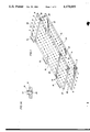
- FIG. 1 shows a perspective view of a connector, without attached wires, made according to the invention.
- FIG. 2 shows a partial cutaway side view of the junction between two sections of seismic cable incorporating the inventive connector and protective boot.
- FIG. 3C is a end view of the assembled split ring keeper of FIGS. 3A and 3B.
- FIG. 1 One configuration of the inventive electrical connector is shown in FIG. 1.
- the connector depicted there is shown without attached wires for the purpose of simplicity of explanation.
- the variation shown in the figure is complex in that it utilizes four separate flexible, magnetic substrates, i.e., first substrate 10, small substrate 32, medium substrate 20, and large substrate 26.
- the first substrate 10 has a number of index pins located therein.
- pins 12 and 14 are embedded in substrate 10 and engage matching index holes 16 and 18 in medium substrate 20.
- Similar mating index pins 22 and index holes 24 are shown in conjunction with large substrate 26.
- pins 28 and index holes 30 are shown in conjunction with the small substrate 32.
- Each of substrates 20, 26, and 32 are shown to have a tab 34 attached to facilitate easy removal from substrate 10.
- Insert 36 desirably has contact face 38 and a wire receiving end 40.
- Contact face 38 may be slightly rounded and extends slightly above the face of substrate 10.
- Wire receiving end 40 is shown to be a hollow cylinder which may be used to accept one or more soldered wires.
- the wire receiving end may also be of other known designs such as the spade end, loop end, or screw receptacle.
- the contact face 38 need not be rounded but may be of such shape as would provide a shallow engagement.
- the contact insert 36 or its contact face 38 be plated with a corrosion resistant metal such as gold if the atmosphere of use requires such an expedient.
- the contact inserts may be of a ferromagnetic material such as iron so as to enhance the magnetic attraction between the substrates and the inserts.
- the inserts may be independently magnetic.
- the substrates desirably are made of a rubberized, magnetic, flexible material having the tradename PLASTIFORM manufactured by the Minnesota Mining and Manufacturing Company, but it is not necessary to do so.
- This proprietary material typically comes with an alternating north-south orientation of the the metallic magnetic particles in the surrounding polymeric matrix. This alternating orientation is depicted by the north-south symbols at the ends of substrate 10 and substrate 32 in FIG. 1. If this material is chosen for use, it is necessary that the constructor of the inventive connector position the index pins, for instance, 12 and 14, and index holes, 16 and 18, and the various contact inserts 36 within particular substrates so that, when two substrates are indexed and in contact, the south orientations in one substrate are adjacent the north orientations in the other substrate. Such a configuration is shown in FIG. 1. It should be apparent from the drawing that the various inserts 36 are placed within opposite substrates so that two contact faces 38 are in contact.
- indexing pins and matching indexing holes are the preferred method of assuring a match between appropriate contact inserts on adjacent substrates
- other indexing means are of course contemplated.
- the edge of adjacent substrates may be fitted into slots on a receptacle mounted in a particular location as in the fire wall of an automobile or airplane.
- a single indexing device having a shape which may be oriented at only one direction with respect to a mating portion may be installed on a substrate.
- a wall may be built up on one substrate which may match the outside shape of one or more mating substrates, much in a way a child's puzzle fits together.
- FIG. 2 shows one desirable use for the inventive connector described with regard to FIG. 1.
- the two substrates 42 and 44 are held in relative proximity by the magnetic forces discussed above. They are not in complete contact since each of the substrate desirably has contact faces (not shown) holding the two substrates slightly apart.
- Each of the contacts is connected to a wire, for instance 46 and 48.
- the accumulation of wires is bundled from each substrate 42, 44 to make a cable 50 and 52 respectively.
- each substrate, wire, and cable is a portion of an attached geophone section, shown generally as 54 and 56.
- cable 50 passes through cable bulkhead 58 and onto hydrophones located farther down the section.
- the hydrophones form no portion of this invention, are well known in the art, and are therefore not described in any great detail.
- the wire bundle 50 is embedded in cable bulkhead 58. No liquid passes through bulkhead 58.
- Cable bulkhead 58 also has one or more stress members 60 embedded therein.
- the stress members are made up of strong stress-carrying materials such as wire rope and should be easily disconnected at connection 62.
- the stress members 60 pass all the way through the hydrophone section, e.g., 54, to its other end where they may make similar connections with the next hydrophone cable section.
- the outside of cable bulkhead 58 carries a sealing means 64, such as an O-ring, or other suitable seal design.
- cable bulkhead 58 is of such a size that is slips readily inside boot assembly 66 and yet is snug against its inside through the sealing means 64. Cable bulkhead 58 is also firmly attached to the pliable skin 68 of the hydrophone section.
- the relationship between cable bulkhead 58 and boot assembly 66 is maintained by a split ring keeper 70 made up of two identical halves 72 as shown in FIGS. 3A, 3B, and 3C.
- FIG. 3A shows an inside view of the split ring keeper half 72. As can be seen, it has a small circumferential slot 74 designed to take the mating portion of cable bulkhead 58. It has a larger circumferential slot 76 to engage the mating portion of boot assembly 66.
- FIG. 3C shows, from an end view, how the two halves are joined.
- the method of disassembling and assembling boot assembly and inventive flexible electric cable should be apparent from the prior description.
- the joining means in holes 78 are removed from each of the split ring keepers 72 found at the end of boot assembly 66.
- the split ring keepers are removed from each end of boot assembly 66.
- Boot assembly 66 is then slid over cable bulkhead 58 thereby exposing stress members 60 and the connector. Stress members 60 are disconnected at stress member connections 62 and finally substrates 42 and 44 are pulled apart. Assembly is performed in the reverse order.
Abstract
This invention is an electrical connector held together by flexible magnetic substrates which also form the support for the connector's electrical contacts. The connector has many uses but is especially suitable for the connection between sections of hydrophone streamer cables.
Description
This invention is a flexible electrical connector comprising a number of flexible magnets and contacts. The invention also involves a cable using the connector. The cable is especially suitable for use as a marine seismic cable.
The exploration of offshore areas for oil and gas is performed almost exclusively with boats towing one or more of a variety of seismic sources and a large number of hydrophones near the surface of the water. Generally, the seismic sources towed behind the boat emit a sharp pulse which travels down through the water, through the seafloor, into the subseafloor region, and reflects off the interface between two geologic layers of differing densities. The reflected pulse then retraces a similar course and is detected by the hydrophones towed behind the seismic boat.
The hydrophones are typically included in a long streamer cable. The cable may be made up of a number of sections, each filled with oil for proper buoyance and containing a number of hydrophones. Modern cables may be two miles or more in length and contain 4,000 hydrophones. A long cable with a great number of hydrophones provides better resolution of the shape of subsurface geologic features than does a shorter streamer with a smaller number of geophones and often does so with less background noise.
As mentioned above, the cable may be made up of a large number of sections. In this way, if the cable is damaged, e.g., by shark bite, it can be pulled onto the boat until the damaged section is brought aboard, the section unplugged, a new section installed and the cable redeployed in the water. Repairs to the damaged cable may be undertaken without substantial interruption of the exploration activity.
One of the greatest sources of unreliability in a marine seismic cable lies with the electrical connectors used to join adjacent sections of cable. It is not uncommon that a cable will have ten fifty-pin connectors at each of its ends. These connectors are located in a boot which may be up to six feet in length. The connectors typically have small delicate pins and sockets which are subject to mismating. Mismating the two connector halves tends to bend or break the small pins. The large number of mating pins requires special tools to overcome the high friction resistance in separating the halves. The boots may be rigid, in contrast to the pliable nature of the section body, to protect the integrity of the sockets. The junction between the pliable cable sections and the rigid boots, therefore, is susceptible to separation or tearing. The cables and connectors described in U.S. Pat. No. 4,204,188 to Weichart et al, issued May 20, 1980, and U.S. Pat. No. 4,260,211 to Mollere, issued Apr. 7, 1981, are typical of this design. A similar device having a pivoted junction between cable sections is disclosed in U.S. Pat. No. 3,350,678 to McLord, issued Oct. 31, 1967.
As noted above, an aspect of the instant invention is the use of flexible magnetic substrate as part of a flexible electrical connector having near-flush contacts imbedded therein.
Other connectors using flush contacts are known. See U.S. Pat. No. 2,234,982 to Ross, issued Mar. 18, 1941 and U.S. Pat. No. 3,080,544 to Statt et al, issued Mar. 5, 1963. U.S. Pat. No. 3,731,258 to Spicer, issued May 1, 1973, discloses both flush contacts and a flexible rubber substrate. None of Ross, Stratt et al, or Spicer, however, disclose a flexible magnetic substrate.
This invention centers around a flexible magnetic electrical connector having a wide variety of uses. The invention also includes a cable incorporating the flexible electric magnetic connector and a boot suitable for protecting the electrical connector if it is used between cable sections.
The connector itself is made up of at least two mating portions which are made up of flexible, nonconductive, magnetic substrate portions. The flexible material of construction appears, to the observer, to be a thin but dense section of rubber. The included magnetic particles, in the material available commercially, are alternately polarized in paths through the material. Each substrate has a number of stubby contact surfaces slightly elevated from the face of the substrate adapted to meet in face to face contact when the substrates are assembled. The contact surfaces are placed on the substrates in positions such that rows of opposite polarities on the substrates are in contact when the connector is assembled.
Index pins are installed in the substrate to ensure proper alignment of contact surfaces.
The flexible magnetic substrates need not be merely mated in a matching pattern of contact surfaces; the substrates may form the junction point of, e.g., a wiring harness where a number of different wiring sections meet at a common connector. In such a case, a number of smaller substrates would connect to a single large substrate.
It may be advantageous in some circumstances to plate the contact surfaces with a material which is not susceptible to corrosion, such as gold. Since the usual wiping action performed by a male/female plug does not occur on the instant invention, other methods of wiping, such as by twisting during assembly, may be desirable.
One particularly suitable use for the invention connector disclosed herein is as the connector between sections of marine seismic cable. As was discussed above, connectors previously used in such service have been hard to separate and prone to bent pins due to mismating during assembly. Since the inventive connector has no pins, these problems are obviated.
Also disclosed is a boot assembly especially suitable for use with the magnetic connector which has an outer housing which can be slid completely out of the area of the connector. In this way the magnetic connector can be grasped with ease during disassembly.
A seismic cable adapted for using the boot assembly is a portion of the inventive concept.
FIG. 1 shows a perspective view of a connector, without attached wires, made according to the invention.
FIG. 1A shows a cutaway side view of a desirable variation of a contact insert suitable for placement in the connector of FIG. 1.
FIG. 2 shows a partial cutaway side view of the junction between two sections of seismic cable incorporating the inventive connector and protective boot.
FIGS. 3A and 3B are top and bottom views of one of the split ring keeper halves used on the boot shown in FIG. 2.
FIG. 3C is a end view of the assembled split ring keeper of FIGS. 3A and 3B.
One configuration of the inventive electrical connector is shown in FIG. 1. The connector depicted there is shown without attached wires for the purpose of simplicity of explanation. The variation shown in the figure is complex in that it utilizes four separate flexible, magnetic substrates, i.e., first substrate 10, small substrate 32, medium substrate 20, and large substrate 26. The first substrate 10 has a number of index pins located therein. For instance, pins 12 and 14 are embedded in substrate 10 and engage matching index holes 16 and 18 in medium substrate 20. Similar mating index pins 22 and index holes 24 are shown in conjunction with large substrate 26. Similarly, pins 28 and index holes 30 are shown in conjunction with the small substrate 32. Each of substrates 20, 26, and 32 are shown to have a tab 34 attached to facilitate easy removal from substrate 10.
Each of the substrates has mounted therein a number of inserts which serve as contacts. These contacts are shown at 36 both in FIG. 1 and, in cross section, in FIG. 1A. Insert 36 desirably has contact face 38 and a wire receiving end 40. Contact face 38 may be slightly rounded and extends slightly above the face of substrate 10. Wire receiving end 40 is shown to be a hollow cylinder which may be used to accept one or more soldered wires. The wire receiving end may also be of other known designs such as the spade end, loop end, or screw receptacle. The contact face 38 need not be rounded but may be of such shape as would provide a shallow engagement. It is contemplated that the contact insert 36 or its contact face 38 be plated with a corrosion resistant metal such as gold if the atmosphere of use requires such an expedient. The contact inserts may be of a ferromagnetic material such as iron so as to enhance the magnetic attraction between the substrates and the inserts. The inserts may be independently magnetic.
The substrates, such as 10, 20, 26, and 32, desirably are made of a rubberized, magnetic, flexible material having the tradename PLASTIFORM manufactured by the Minnesota Mining and Manufacturing Company, but it is not necessary to do so. This proprietary material typically comes with an alternating north-south orientation of the the metallic magnetic particles in the surrounding polymeric matrix. This alternating orientation is depicted by the north-south symbols at the ends of substrate 10 and substrate 32 in FIG. 1. If this material is chosen for use, it is necessary that the constructor of the inventive connector position the index pins, for instance, 12 and 14, and index holes, 16 and 18, and the various contact inserts 36 within particular substrates so that, when two substrates are indexed and in contact, the south orientations in one substrate are adjacent the north orientations in the other substrate. Such a configuration is shown in FIG. 1. It should be apparent from the drawing that the various inserts 36 are placed within opposite substrates so that two contact faces 38 are in contact.
It is not necessary that there be a one to one conformance between the number of contact inserts in adjacent substrates. It is contemplated that, for instance, should it be found necessary to direct a number of wire leads to a single circuit point such as an electrical ground, a single substrate with a number of contact inserts may be placed directly onto a single conductive substrate.
As mentioned above, there is no wiping action in this connector tending to keep the contacts clean. Consequently, in some services it may be necessary to modify the index pins so that during assembly one substrate of the connector is twisted in relation to the other to perform wiping movement between a number of contact faces 38.
Similarly, although indexing pins and matching indexing holes are the preferred method of assuring a match between appropriate contact inserts on adjacent substrates, other indexing means are of course contemplated. For instance, the edge of adjacent substrates may be fitted into slots on a receptacle mounted in a particular location as in the fire wall of an automobile or airplane. A single indexing device having a shape which may be oriented at only one direction with respect to a mating portion may be installed on a substrate. A wall may be built up on one substrate which may match the outside shape of one or more mating substrates, much in a way a child's puzzle fits together.
FIG. 2 shows one desirable use for the inventive connector described with regard to FIG. 1. The two substrates 42 and 44 are held in relative proximity by the magnetic forces discussed above. They are not in complete contact since each of the substrate desirably has contact faces (not shown) holding the two substrates slightly apart. Each of the contacts is connected to a wire, for instance 46 and 48. The accumulation of wires is bundled from each substrate 42, 44 to make a cable 50 and 52 respectively. In this variation, each substrate, wire, and cable, is a portion of an attached geophone section, shown generally as 54 and 56. For the purposes of illustration, speaking of the section 54 on the right end of FIG. 2, cable 50 passes through cable bulkhead 58 and onto hydrophones located farther down the section. The hydrophones form no portion of this invention, are well known in the art, and are therefore not described in any great detail. The wire bundle 50 is embedded in cable bulkhead 58. No liquid passes through bulkhead 58. Cable bulkhead 58 also has one or more stress members 60 embedded therein. The stress members are made up of strong stress-carrying materials such as wire rope and should be easily disconnected at connection 62. The stress members 60 pass all the way through the hydrophone section, e.g., 54, to its other end where they may make similar connections with the next hydrophone cable section. The outside of cable bulkhead 58 carries a sealing means 64, such as an O-ring, or other suitable seal design. The outside of cable bulkhead 58 is of such a size that is slips readily inside boot assembly 66 and yet is snug against its inside through the sealing means 64. Cable bulkhead 58 is also firmly attached to the pliable skin 68 of the hydrophone section. The relationship between cable bulkhead 58 and boot assembly 66 is maintained by a split ring keeper 70 made up of two identical halves 72 as shown in FIGS. 3A, 3B, and 3C. FIG. 3A shows an inside view of the split ring keeper half 72. As can be seen, it has a small circumferential slot 74 designed to take the mating portion of cable bulkhead 58. It has a larger circumferential slot 76 to engage the mating portion of boot assembly 66. There are holes 78 for inserting screws or other means to join the two split ring keeper halves together over the juncture of boot assembly 66 and a cable bulkhead forming the end of a hydrophone cable section. FIG. 3C shows, from an end view, how the two halves are joined.
The method of disassembling and assembling boot assembly and inventive flexible electric cable should be apparent from the prior description. However, the joining means in holes 78 are removed from each of the split ring keepers 72 found at the end of boot assembly 66. The split ring keepers are removed from each end of boot assembly 66. Boot assembly 66 is then slid over cable bulkhead 58 thereby exposing stress members 60 and the connector. Stress members 60 are disconnected at stress member connections 62 and finally substrates 42 and 44 are pulled apart. Assembly is performed in the reverse order.
The present invention has been described and illustrated by means of specific embodiments, it is to be understood that numerous changes and modifications may be made therein without departing from the spirit and scope of the invention as defined in the following claims.
Claims (18)
1. An electrical connector comprising:
at least two flexible, magnetic and substantially electrically non-conductive substrates each having contact means mounted therein with contact faces on a first side of each of said substrates and adapted to meet in face to face contact when said substrates are juxtaposed, each said contact means adapted to accept at least one electrical wire on a second side of said substrates, and
indexing means adapted to permit said at least two substrates to be juxtaposed in a predetermined position.
2. The connector of claim 1 wherein each of said substrate has attached thereto a tab for separating said substrate from juxtaposition with another.
3. The connector of claim 1 wherein said indexing means comprise indexing pins and holes.
4. The connector of claim 1 wherein said substrate is comprised of a thin rubbery material having magnetic particles dispersed therein.
5. The connector of claim 4 wherein said magnetic particles are dispersed in alternating rows of opposite magnetic orientation.
6. A watertight electrical connector assembly comprising:
a first and a second flexible, magnetic, and substantially electrically non-conductive substrate, each having contact means mounted therein with contact faces on a first side of each of said substrates and adapted to meet in face to face contact when said substrates are juxtaposed,
electrical wires connected to each said contact means on a second side of each of said substrates, said wires from said first and second substrates forming a first and second bundle respectively,
said first and second bundles fixably attached in first and second bulkheads, said bulkheads having sealing means disposed thereabout,
boot means slidable over and extending from said first bulkhead to said second bulkhead and sealing against said sealing means disposed in said bulkheads, and
first and second split ring keepers adapted to maintain said boot in sealing contact with said first and second bulkheads.
7. The connector assembly of claim 6 wherein each said substrate has attached thereto a tab for separating each said substrate from juxtaposition with another.
8. The connector assembly of claim 6 wherein said connector assembly further comprises indexing means adapted to permit said substrates to be juxtaposed in a predetermined position.
9. The connector assembly of claim 6 wherein said substrate is comprised of a thin rubbery material having magnetic particles dispersed therein.
10. The connector assembly of claim 9 wherein said magnetic particles are dispersed in alternating rows of opposite magnetic orientation.
11. The connector assembly of claim 6 wherein said sealing means comprise "O" rings.
12. The connector assembly of claim 6 wherein said assembly additionally comprises stress members extending at least from said first bulkhead to said second bulkhead.
13. A hydrophone streamer cable section comprising:
a flexible hydrophone housing containing at least one hydrophone, having two ends, and terminated by a bulkhead at each said end,
electrical connector means mounted on each said bulkhead, each said connector means being comprised of a flexible, magnetic, and substantially electrically non-conductive substrate having contact means mounted therein with contact faces on a first side of said substrate, said contact means adapted to accept an electrical wire extending from said at least one hydrophone through a bulkhead to a second side of said substrate, and having indexing means to permit said connector means to be juxtaposed in a predetermined position to a similar connector.
14. The cable of claim 13 wherein each said substrate has attached thereto a tab for separating said substrate from juxtaposition with another.
15. The cable of claim 13 wherein said indexing means comprise indexing pins and holes.
16. The cable of claim 13 wherein said substrate is comprised of a thin rubbery material having magnetic particles dispersed therein.
17. The cable of claim 16 wherein said magnetic particles are dispersed in alternating rows of opposite magnetic orientation.
18. The cable of claim 13 wherein stress members extend from bulkhead to bulkhead and are fixedly attached thereto.
Priority Applications (1)
| Application Number | Priority Date | Filing Date | Title |
|---|---|---|---|
| US06/505,660 US4479685A (en) | 1983-06-20 | 1983-06-20 | Flexible magnetic electrical connector and cable incorporating that connector |
Applications Claiming Priority (1)
| Application Number | Priority Date | Filing Date | Title |
|---|---|---|---|
| US06/505,660 US4479685A (en) | 1983-06-20 | 1983-06-20 | Flexible magnetic electrical connector and cable incorporating that connector |
Publications (1)
| Publication Number | Publication Date |
|---|---|
| US4479685A true US4479685A (en) | 1984-10-30 |
Family
ID=24011267
Family Applications (1)
| Application Number | Title | Priority Date | Filing Date |
|---|---|---|---|
| US06/505,660 Expired - Fee Related US4479685A (en) | 1983-06-20 | 1983-06-20 | Flexible magnetic electrical connector and cable incorporating that connector |
Country Status (1)
| Country | Link |
|---|---|
| US (1) | US4479685A (en) |
Cited By (14)
| Publication number | Priority date | Publication date | Assignee | Title |
|---|---|---|---|---|
| US4966556A (en) * | 1989-06-13 | 1990-10-30 | General Datacomm, Inc. | Electrical connector for direct connection to plated through holes in circuit board |
| US5049084A (en) * | 1989-12-05 | 1991-09-17 | Rogers Corporation | Electrical circuit board interconnect |
| US5215471A (en) * | 1989-06-13 | 1993-06-01 | General Datacomm, Inc. | Electrical connectors having tapered spring contact elements for direct mating to holes |
| US5256073A (en) * | 1989-06-13 | 1993-10-26 | General Datacomm, Inc. | Electrical connectors for direct connection to plated through holes in circuit board |
| US5366380A (en) * | 1989-06-13 | 1994-11-22 | General Datacomm, Inc. | Spring biased tapered contact elements for electrical connectors and integrated circuit packages |
| US5425649A (en) * | 1989-06-13 | 1995-06-20 | General Datacomm, Inc. | Connector system having switching and testing functions using tapered spring contact elements and actuators therefor |
| US6340302B1 (en) | 2001-02-06 | 2002-01-22 | Micron Technology, Inc. | Apparatus for establishing an electrical connection with a wafer to facilitate wafer-level burn-in and methods |
| US20100197148A1 (en) * | 2009-02-02 | 2010-08-05 | Apex Technologies, Inc. | Flexible magnetic interconnects |
| US8798675B2 (en) | 2012-09-03 | 2014-08-05 | iBlaidZ, Inc. | System of stacked devices |
| FR3020955A1 (en) * | 2014-05-19 | 2015-11-20 | Commissariat Energie Atomique | ELECTRICAL CONNECTOR, IN PARTICULAR FOR A CUTANE DEVICE. |
| US9300081B2 (en) | 2010-02-02 | 2016-03-29 | Charles Albert Rudisill | Interposer connectors with magnetic components |
| US9703321B2 (en) | 2013-07-09 | 2017-07-11 | I-Blades, Inc. | Snap on wearable module |
| US10680383B2 (en) | 2013-03-14 | 2020-06-09 | Apex Technologies, Inc. | Linear electrode systems for module attachment with non-uniform axial spacing |
| US11733411B1 (en) * | 2021-07-21 | 2023-08-22 | The United States Of America As Represented By The Secretary Of The Navy | Clamshell mechanism for towed array bootable bulkhead |
Citations (9)
| Publication number | Priority date | Publication date | Assignee | Title |
|---|---|---|---|---|
| US3812455A (en) * | 1973-01-16 | 1974-05-21 | Whitehall Electronics Corp | Marine seismic streamer connector structure |
| US4045107A (en) * | 1975-08-22 | 1977-08-30 | Walker-Hall-Sears, Inc. | Multi-contact connectors with identical contacts |
| US4118090A (en) * | 1977-05-23 | 1978-10-03 | Luigi Giovanni Del Mei | Electrical contact devices |
| US4166663A (en) * | 1976-11-11 | 1979-09-04 | Western Geophysical Co. Of America | Multi-contact connectors with individual resilient contact inserts |
| US4195894A (en) * | 1977-05-04 | 1980-04-01 | Amerace Corporation | Electrical connector and electrical connection system employing the same |
| US4204188A (en) * | 1977-05-04 | 1980-05-20 | Prakla-Seismos Gmbh | Cable for sea seismic exploration |
| US4260211A (en) * | 1979-08-23 | 1981-04-07 | Western Geophysical Co. Of America | Quick coupler for seismic streamer sections |
| US4317185A (en) * | 1980-06-06 | 1982-02-23 | Western Geophysical Co. Of America | Streamer cable towing link |
| US4398781A (en) * | 1981-10-09 | 1983-08-16 | Amf Incorporated | Sealing assembly for a geophysical cable connector |
-
1983
- 1983-06-20 US US06/505,660 patent/US4479685A/en not_active Expired - Fee Related
Patent Citations (9)
| Publication number | Priority date | Publication date | Assignee | Title |
|---|---|---|---|---|
| US3812455A (en) * | 1973-01-16 | 1974-05-21 | Whitehall Electronics Corp | Marine seismic streamer connector structure |
| US4045107A (en) * | 1975-08-22 | 1977-08-30 | Walker-Hall-Sears, Inc. | Multi-contact connectors with identical contacts |
| US4166663A (en) * | 1976-11-11 | 1979-09-04 | Western Geophysical Co. Of America | Multi-contact connectors with individual resilient contact inserts |
| US4195894A (en) * | 1977-05-04 | 1980-04-01 | Amerace Corporation | Electrical connector and electrical connection system employing the same |
| US4204188A (en) * | 1977-05-04 | 1980-05-20 | Prakla-Seismos Gmbh | Cable for sea seismic exploration |
| US4118090A (en) * | 1977-05-23 | 1978-10-03 | Luigi Giovanni Del Mei | Electrical contact devices |
| US4260211A (en) * | 1979-08-23 | 1981-04-07 | Western Geophysical Co. Of America | Quick coupler for seismic streamer sections |
| US4317185A (en) * | 1980-06-06 | 1982-02-23 | Western Geophysical Co. Of America | Streamer cable towing link |
| US4398781A (en) * | 1981-10-09 | 1983-08-16 | Amf Incorporated | Sealing assembly for a geophysical cable connector |
Cited By (27)
| Publication number | Priority date | Publication date | Assignee | Title |
|---|---|---|---|---|
| US4966556A (en) * | 1989-06-13 | 1990-10-30 | General Datacomm, Inc. | Electrical connector for direct connection to plated through holes in circuit board |
| US5215471A (en) * | 1989-06-13 | 1993-06-01 | General Datacomm, Inc. | Electrical connectors having tapered spring contact elements for direct mating to holes |
| US5256073A (en) * | 1989-06-13 | 1993-10-26 | General Datacomm, Inc. | Electrical connectors for direct connection to plated through holes in circuit board |
| US5366380A (en) * | 1989-06-13 | 1994-11-22 | General Datacomm, Inc. | Spring biased tapered contact elements for electrical connectors and integrated circuit packages |
| US5425649A (en) * | 1989-06-13 | 1995-06-20 | General Datacomm, Inc. | Connector system having switching and testing functions using tapered spring contact elements and actuators therefor |
| US5049084A (en) * | 1989-12-05 | 1991-09-17 | Rogers Corporation | Electrical circuit board interconnect |
| US6340302B1 (en) | 2001-02-06 | 2002-01-22 | Micron Technology, Inc. | Apparatus for establishing an electrical connection with a wafer to facilitate wafer-level burn-in and methods |
| US20020106911A1 (en) * | 2001-02-06 | 2002-08-08 | Ladd John W. | Apparatus for establishing an electrical connection with a wafer to facilitate wafer-level burn-in and methods |
| US7032288B2 (en) | 2001-02-06 | 2006-04-25 | Micron Technology, Inc. | Methods for magnetically establishing an electrical connection with a contact of a semiconductor device component |
| US20060191135A1 (en) * | 2001-02-06 | 2006-08-31 | Ladd John W | Methods for establishing electrical connections by drawing one or both of an element of an electrical connector and a contact toward the other |
| US7266879B2 (en) | 2001-02-06 | 2007-09-11 | Micron Technology, Inc. | Method for magnetically establishing an electrical connection with a contact of a semiconductor device component |
| US8187006B2 (en) | 2009-02-02 | 2012-05-29 | Apex Technologies, Inc | Flexible magnetic interconnects |
| US20100197148A1 (en) * | 2009-02-02 | 2010-08-05 | Apex Technologies, Inc. | Flexible magnetic interconnects |
| US9300081B2 (en) | 2010-02-02 | 2016-03-29 | Charles Albert Rudisill | Interposer connectors with magnetic components |
| US9583871B1 (en) | 2010-05-13 | 2017-02-28 | Apex Technologies, Inc. | Electrical connector system with ferromagnetic actuators |
| US8798675B2 (en) | 2012-09-03 | 2014-08-05 | iBlaidZ, Inc. | System of stacked devices |
| US9064356B2 (en) | 2012-09-03 | 2015-06-23 | iBlaidZ, Inc. | System of stacked devices |
| US9761068B2 (en) | 2012-09-03 | 2017-09-12 | I-Blades, Inc. | System of stacked devices |
| US9576409B2 (en) | 2012-09-03 | 2017-02-21 | I-Blades, Inc. | Method and system for smart contact arrays |
| US10680383B2 (en) | 2013-03-14 | 2020-06-09 | Apex Technologies, Inc. | Linear electrode systems for module attachment with non-uniform axial spacing |
| US9703321B2 (en) | 2013-07-09 | 2017-07-11 | I-Blades, Inc. | Snap on wearable module |
| US20170095656A1 (en) * | 2014-05-19 | 2017-04-06 | Commissariat A L'energie Atomique Et Aux Energies Alternatives | Electrical connector, in particular for a cutaneous device |
| WO2015177682A1 (en) * | 2014-05-19 | 2015-11-26 | Commissariat A L'energie Atomique Et Aux Energies Alternatives | Electrical connector, in particular for a cutaneous device |
| US10213594B2 (en) * | 2014-05-19 | 2019-02-26 | Commissariat A L'energie Atomique Et Aux Energies Alternatives | Electrical connector, in particular for a cutaneous device |
| FR3020955A1 (en) * | 2014-05-19 | 2015-11-20 | Commissariat Energie Atomique | ELECTRICAL CONNECTOR, IN PARTICULAR FOR A CUTANE DEVICE. |
| US10814124B2 (en) * | 2014-05-19 | 2020-10-27 | Commissariat A L'energie Atomique Et Aux Energies Alternatives | Electrical connector, in particular for a cutaneous device |
| US11733411B1 (en) * | 2021-07-21 | 2023-08-22 | The United States Of America As Represented By The Secretary Of The Navy | Clamshell mechanism for towed array bootable bulkhead |
Similar Documents
| Publication | Publication Date | Title |
|---|---|---|
| US4479685A (en) | Flexible magnetic electrical connector and cable incorporating that connector | |
| US6716063B1 (en) | Electrical cable insert | |
| EP0730322B1 (en) | Underwater electrical connector | |
| CA1158760A (en) | Seismic streamer connector assembly | |
| US5704799A (en) | Field repairable electrical connector | |
| US3391381A (en) | Shielded electrical connector | |
| EP0727845B1 (en) | Field repairable electrical connector | |
| US6034923A (en) | Seismic sensor pod | |
| US4351036A (en) | Submarine cable connector link | |
| US4917632A (en) | Seismic takeout connector | |
| US2825039A (en) | Connector for detector cable | |
| US4166663A (en) | Multi-contact connectors with individual resilient contact inserts | |
| GB2212992A (en) | Insulating and retaining spark plug connectors | |
| US4526430A (en) | Marine seismic cable connector | |
| EP0199877A1 (en) | Combination seismic cable | |
| US3546657A (en) | High contact density underwater connector | |
| US3489987A (en) | Underwater electrical connector | |
| CN109301563A (en) | A kind of watertight connector | |
| US6719578B1 (en) | Submersible electrical cable connector | |
| US3089114A (en) | Electrical connector | |
| US3413407A (en) | Connector for underwater cable | |
| US4399318A (en) | EMI Shielding enclosure for a cable connector | |
| US5989065A (en) | High performance Mil-C-26500 | |
| JPH02216782A (en) | Electric connection fitted with filter | |
| US5878001A (en) | Repairable waterproof geophone housing |
Legal Events
| Date | Code | Title | Description |
|---|---|---|---|
| AS | Assignment |
Owner name: EXXON PRODUCTION RESEARCH COMPANY, A DE CORP. Free format text: ASSIGNMENT OF ASSIGNORS INTEREST.;ASSIGNOR:KIRBY, ROBERT A.;REEL/FRAME:004152/0198 Effective date: 19830617 |
|
| FPAY | Fee payment |
Year of fee payment: 4 |
|
| REMI | Maintenance fee reminder mailed | ||
| LAPS | Lapse for failure to pay maintenance fees | ||
| FP | Lapsed due to failure to pay maintenance fee |
Effective date: 19921101 |
|
| STCH | Information on status: patent discontinuation |
Free format text: PATENT EXPIRED DUE TO NONPAYMENT OF MAINTENANCE FEES UNDER 37 CFR 1.362 |