US4454915A - In situ retorting of oil shale with air, steam, and recycle gas - Google Patents
In situ retorting of oil shale with air, steam, and recycle gas Download PDFInfo
- Publication number
- US4454915A US4454915A US06/391,473 US39147382A US4454915A US 4454915 A US4454915 A US 4454915A US 39147382 A US39147382 A US 39147382A US 4454915 A US4454915 A US 4454915A
- Authority
- US
- United States
- Prior art keywords
- shale
- oil
- gases
- retort
- oil shale
- Prior art date
- Legal status (The legal status is an assumption and is not a legal conclusion. Google has not performed a legal analysis and makes no representation as to the accuracy of the status listed.)
- Expired - Fee Related
Links
- 239000004058 oil shale Substances 0.000 title claims abstract description 80
- 238000011065 in-situ storage Methods 0.000 title description 19
- 239000007789 gas Substances 0.000 claims abstract description 107
- 239000003079 shale oil Substances 0.000 claims abstract description 22
- 238000000034 method Methods 0.000 claims description 23
- 230000008569 process Effects 0.000 claims description 19
- 229930195733 hydrocarbon Natural products 0.000 claims description 14
- 150000002430 hydrocarbons Chemical class 0.000 claims description 14
- XLYOFNOQVPJJNP-UHFFFAOYSA-N water Substances O XLYOFNOQVPJJNP-UHFFFAOYSA-N 0.000 claims description 12
- 239000004215 Carbon black (E152) Substances 0.000 claims description 6
- 238000010438 heat treatment Methods 0.000 claims description 2
- 238000004064 recycling Methods 0.000 claims description 2
- 208000037063 Thinness Diseases 0.000 claims 1
- 230000003247 decreasing effect Effects 0.000 claims 1
- OKTJSMMVPCPJKN-UHFFFAOYSA-N Carbon Chemical group [C] OKTJSMMVPCPJKN-UHFFFAOYSA-N 0.000 abstract description 21
- 239000010880 spent shale Substances 0.000 abstract description 15
- 239000003921 oil Substances 0.000 description 12
- VNWKTOKETHGBQD-UHFFFAOYSA-N methane Chemical compound C VNWKTOKETHGBQD-UHFFFAOYSA-N 0.000 description 10
- 229910052799 carbon Inorganic materials 0.000 description 9
- 239000000446 fuel Substances 0.000 description 9
- 239000007788 liquid Substances 0.000 description 9
- 239000000047 product Substances 0.000 description 8
- 238000002485 combustion reaction Methods 0.000 description 7
- 239000000203 mixture Substances 0.000 description 7
- IJGRMHOSHXDMSA-UHFFFAOYSA-N Atomic nitrogen Chemical compound N#N IJGRMHOSHXDMSA-UHFFFAOYSA-N 0.000 description 6
- 230000015572 biosynthetic process Effects 0.000 description 5
- 238000005755 formation reaction Methods 0.000 description 5
- 239000002737 fuel gas Substances 0.000 description 5
- QGZKDVFQNNGYKY-UHFFFAOYSA-N Ammonia Chemical compound N QGZKDVFQNNGYKY-UHFFFAOYSA-N 0.000 description 4
- CURLTUGMZLYLDI-UHFFFAOYSA-N Carbon dioxide Chemical compound O=C=O CURLTUGMZLYLDI-UHFFFAOYSA-N 0.000 description 4
- ATUOYWHBWRKTHZ-UHFFFAOYSA-N Propane Chemical compound CCC ATUOYWHBWRKTHZ-UHFFFAOYSA-N 0.000 description 4
- QQONPFPTGQHPMA-UHFFFAOYSA-N Propene Chemical compound CC=C QQONPFPTGQHPMA-UHFFFAOYSA-N 0.000 description 4
- UGFAIRIUMAVXCW-UHFFFAOYSA-N Carbon monoxide Chemical compound [O+]#[C-] UGFAIRIUMAVXCW-UHFFFAOYSA-N 0.000 description 3
- 238000005065 mining Methods 0.000 description 3
- 239000003345 natural gas Substances 0.000 description 3
- 229910052757 nitrogen Inorganic materials 0.000 description 3
- 238000000197 pyrolysis Methods 0.000 description 3
- 239000011800 void material Substances 0.000 description 3
- RWSOTUBLDIXVET-UHFFFAOYSA-N Dihydrogen sulfide Chemical compound S RWSOTUBLDIXVET-UHFFFAOYSA-N 0.000 description 2
- OTMSDBZUPAUEDD-UHFFFAOYSA-N Ethane Chemical compound CC OTMSDBZUPAUEDD-UHFFFAOYSA-N 0.000 description 2
- VGGSQFUCUMXWEO-UHFFFAOYSA-N Ethene Chemical compound C=C VGGSQFUCUMXWEO-UHFFFAOYSA-N 0.000 description 2
- 229910021529 ammonia Inorganic materials 0.000 description 2
- 238000005422 blasting Methods 0.000 description 2
- 239000001569 carbon dioxide Substances 0.000 description 2
- 229910002092 carbon dioxide Inorganic materials 0.000 description 2
- 229910002091 carbon monoxide Inorganic materials 0.000 description 2
- JJWKPURADFRFRB-UHFFFAOYSA-N carbonyl sulfide Chemical compound O=C=S JJWKPURADFRFRB-UHFFFAOYSA-N 0.000 description 2
- 239000010779 crude oil Substances 0.000 description 2
- 239000001257 hydrogen Substances 0.000 description 2
- 229910052739 hydrogen Inorganic materials 0.000 description 2
- 150000002431 hydrogen Chemical class 0.000 description 2
- 229910000037 hydrogen sulfide Inorganic materials 0.000 description 2
- 239000000463 material Substances 0.000 description 2
- 239000003595 mist Substances 0.000 description 2
- 239000002245 particle Substances 0.000 description 2
- 239000001294 propane Substances 0.000 description 2
- 238000000746 purification Methods 0.000 description 2
- 230000001105 regulatory effect Effects 0.000 description 2
- 230000004044 response Effects 0.000 description 2
- 238000005245 sintering Methods 0.000 description 2
- 239000007787 solid Substances 0.000 description 2
- -1 steam Chemical compound 0.000 description 2
- 239000013589 supplement Substances 0.000 description 2
- 238000004227 thermal cracking Methods 0.000 description 2
- NINIDFKCEFEMDL-UHFFFAOYSA-N Sulfur Chemical compound [S] NINIDFKCEFEMDL-UHFFFAOYSA-N 0.000 description 1
- QVGXLLKOCUKJST-UHFFFAOYSA-N atomic oxygen Chemical compound [O] QVGXLLKOCUKJST-UHFFFAOYSA-N 0.000 description 1
- 239000003245 coal Substances 0.000 description 1
- 239000000571 coke Substances 0.000 description 1
- 238000005094 computer simulation Methods 0.000 description 1
- 230000007423 decrease Effects 0.000 description 1
- 230000001419 dependent effect Effects 0.000 description 1
- 238000005474 detonation Methods 0.000 description 1
- 238000004821 distillation Methods 0.000 description 1
- 239000000428 dust Substances 0.000 description 1
- 230000000694 effects Effects 0.000 description 1
- 239000002360 explosive Substances 0.000 description 1
- 238000000605 extraction Methods 0.000 description 1
- 239000003546 flue gas Substances 0.000 description 1
- 239000012530 fluid Substances 0.000 description 1
- 239000012634 fragment Substances 0.000 description 1
- 238000002309 gasification Methods 0.000 description 1
- 230000005484 gravity Effects 0.000 description 1
- 238000005984 hydrogenation reaction Methods 0.000 description 1
- 238000002347 injection Methods 0.000 description 1
- 239000007924 injection Substances 0.000 description 1
- 230000001788 irregular Effects 0.000 description 1
- 238000012986 modification Methods 0.000 description 1
- 230000004048 modification Effects 0.000 description 1
- 239000011368 organic material Substances 0.000 description 1
- 239000005416 organic matter Substances 0.000 description 1
- 239000001301 oxygen Substances 0.000 description 1
- 229910052760 oxygen Inorganic materials 0.000 description 1
- 239000003209 petroleum derivative Substances 0.000 description 1
- 230000008707 rearrangement Effects 0.000 description 1
- 238000011084 recovery Methods 0.000 description 1
- 239000011435 rock Substances 0.000 description 1
- 239000002904 solvent Substances 0.000 description 1
- 238000006467 substitution reaction Methods 0.000 description 1
- 229910052717 sulfur Inorganic materials 0.000 description 1
- 239000011593 sulfur Substances 0.000 description 1
- 239000011269 tar Substances 0.000 description 1
- 230000008016 vaporization Effects 0.000 description 1
Images
Classifications
-
- E—FIXED CONSTRUCTIONS
- E21—EARTH DRILLING; MINING
- E21C—MINING OR QUARRYING
- E21C41/00—Methods of underground or surface mining; Layouts therefor
- E21C41/16—Methods of underground mining; Layouts therefor
- E21C41/24—Methods of underground mining; Layouts therefor for oil-bearing deposits
-
- E—FIXED CONSTRUCTIONS
- E21—EARTH DRILLING; MINING
- E21B—EARTH DRILLING, e.g. DEEP DRILLING; OBTAINING OIL, GAS, WATER, SOLUBLE OR MELTABLE MATERIALS OR A SLURRY OF MINERALS FROM WELLS
- E21B43/00—Methods or apparatus for obtaining oil, gas, water, soluble or meltable materials or a slurry of minerals from wells
- E21B43/16—Enhanced recovery methods for obtaining hydrocarbons
- E21B43/24—Enhanced recovery methods for obtaining hydrocarbons using heat, e.g. steam injection
- E21B43/243—Combustion in situ
- E21B43/247—Combustion in situ in association with fracturing processes or crevice forming processes
- E21B43/248—Combustion in situ in association with fracturing processes or crevice forming processes using explosives
-
- E—FIXED CONSTRUCTIONS
- E21—EARTH DRILLING; MINING
- E21B—EARTH DRILLING, e.g. DEEP DRILLING; OBTAINING OIL, GAS, WATER, SOLUBLE OR MELTABLE MATERIALS OR A SLURRY OF MINERALS FROM WELLS
- E21B43/00—Methods or apparatus for obtaining oil, gas, water, soluble or meltable materials or a slurry of minerals from wells
- E21B43/34—Arrangements for separating materials produced by the well
- E21B43/40—Separation associated with re-injection of separated materials
Definitions
- This invention relates to a process for underground retorting of oil shale.
- oil shale is a fine-grained sedimentary rock stratified in horizontal layers with a variable richness of kerogen content. Kerogen has limited solubility in ordinary solvents and therefore cannot be recovered by extraction. Upon heating oil shale to a sufficient temperature, the kerogen is thermally decomposed to liberate vapors, mist, and liquid droplets of shale oil and light hydrocarbon gases such as methane, ethane, ethene, propane and propene, as well as other products such as hydrogen, nitrogen, carbon dioxide, carbon monoxide, ammonia, steam and hydrogen sulfide. A carbon residue typically remains on the retorted shale.
- Shale oil is not a naturally occurring product, but is formed by the pyrolysis of kerogen in the oil shale.
- Crude shale oil sometimes referred to as “retort oil,” is the liquid oil product recovered from the liberated effluent of an oil shale retort.
- Synthetic crude oil (syncrude) is the upgraded oil product resulting from the hydrogenation of crude shale oil.
- Underground formations of oil shale contain various layers, deposits or strata of rich and lean oil shale.
- the relative richness, leanness, and depth of these layers typically vary throughout the underground formation and depend upon the particular location of the formation.
- the process of pyrolyzing the kerogen in oil shale, known as retorting, to form liberated hydrocarbons can be done in surface retorts in aboveground vessels or in in situ retorts under ground. In situ retorts require less mining and handling than surface retorts.
- a flame front is passed downward through a bed of rubblized oil shale to liberate shale oil, off gases and residual water. Rich oil shale yields more shale oil and leaves more carbon residue on the retorted shale than lean oil shale. When a sufficient quantity of carbon residue remains on the shale, it provides fuel for the flame front. When insufficient carbon residue exists, as is the case with lean shale, some of the oil produced is not liberated, but is burned to supply the needed fuel.
- in situ retorts There are two types of in situ retorts: true in situ retorts and modified in situ retorts.
- true in situ retorts none of the shale is mined, holes are drilled into the formation, and the oil shale is explosively rubblized, if necessary, and then retorted.
- modified in situ retorts some of the oil shale is removed by mining to create a cavity or void space in the retorting area. The cavity provides extra space which is filled with rubble after blasting to provide void space in the bed. The oil shale which has been removed is conveyed to the surface and is available for aboveground retorting.
- An improved process and feed gas composition are provided for in situ retorting of oil shale, which is effective, efficient and relatively easy to use.
- a flame front is ignited and passed through an in situ oil shale retort to liberate shale oil.
- the flame front is supported and driven through the retort with a special flame front-supporting feed gas consisting of air, steam and retort off gases.
- Air in the feed gas provides oxygen to sustain the flame front.
- Steam in the feed gas moderates the temperature of the flame front in order to prevent excessive temperatures, minimize thermal cracking and increase the heat capacity of the gas.
- Off gases in the feed gas supply the fuel required to support the flame front through layers of lean oil shale, which typically contain inadequate amounts of residual carbon to support the flame front.
- Off gases in the feed gas are preferably obtained from effluent retort off gases produced in the same retort, although they can be obtained from another underground retort or from a surface retort.
- the proportion of air, steam and off gases in the feed gas is varied in response to the oil yield or the leanness, richness and/or kerogen content of the raw oil shale being heated by the flame front, or in proportion to the amount of carbon residue on the retorted shale being combusted by the flame front.
- the quantity of off gas increases as the shale richness decreases and vice versa. No off gas is needed with a sufficiently rich shale that deposits an adequate supply of coke.
- the process is preferably carried out in a generally upright, modified in situ retort, although it can be carried out in a horizontal, irregular shaped and/or a true in situ retort.
- volume ratios used throughout this application are relative to the condition of the subject gases at a temperature of 77° F. (25° C.) at atmospheric pressure.
- retorted oil shale and “retorted shale” refer to oil shale which has been retorted to liberate hydrocarbons leaving an organic material containing carbon residue.
- spent oil shale and "spent shale” as used herein, mean retorted shale from which most of the carbon residue has been removed by combustion.
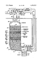
- FIGURE is a schematic cross-sectional view of an in situ retort for carrying out a process and using a special feed gas in accordance with principles of the present invention.
- an underground, modified in situ, oil shale retort 10 located in a subterranean formation 12 of oil shale is covered with an overburden 14.
- Retort 10 is elongated, upright and generally box-shaped, with a flat top or dome-shaped roof 16.
- Retort 10 is filled with an irregularly packed, fluid permeable, rubblized mass or bed 18 of raw oil shale fragments containing different amounts of kerogen.
- the average particle size of the fragmented oil shale is up to 5 inches, although large oil shale boulders of 10 inches or more and minute oil shale particles or fines may be present.
- Bed 18 contains rubblized layers of rich oil shale 20 and 22 and lean oil shale 24 and 26 of different depths.
- Lean oil shale is more brittle and fragile than rich oil shale and yields from about 7.7 to 15 gallons of shale oil per ton of raw oil shale.
- Rich oil shale yields more than 15 gallons of shale oil to as much as 32 gallons or more of shale oil per ton of raw oil shale.
- Very rich oil shale yields as much as 65 to 85 gallons of shale oil per ton of raw oil shale.
- Bed 18 is formed by first mining an access tunnel or drift 28 extending horizontally into the bottom of retort 10 and removing from 2% to 40% and preferably from 25% to 35% by volume of the raw oil shale from the retort to form a cavity or void space.
- the removed oil shale is conveyed to the surface and is available for retorting in an aboveground retort.
- the mass of oil shale above the cavity is then fragmented and expanded by detonation of explosives to form the rubblized mass which substantially fills the cavity.
- the cavity after blasting, provides the desired porosity in the rubble bed.
- a fuel gas line 30 extends from above ground level through overburden 14 into the top 16 of retort 10. The extent and rate of fuel gas flowing through line 32 are regulated and controlled by fuel gas valve 32. Downhole burners 34 extend downwardly through the roof 16 of the retort to a location slightly above the top 36 of the bed 18 of oil shale.
- a feed gas line 38 extends from above ground level through overburden 14 into the roof 16 of retort 10. More than one feed gas line can be used. Feed line 38 is connected to: an air supply 40, such as a compressor or air blower, through air line 42; a steam source 44, such as a steam generator, superheater or boiler, through steam line 46; and recycle gas source 48, through recycle gas line 50. Retort gas in excess of the quantity desired as recycle gas is withdrawn from the system through bleed line 51 upon opening bleed line valve 53. The air, steam and recycle off gas are fed together into retort 10 through common feed gas line 38, although they can be fed separately into the retort through separate lines, if desired. The extent and rate of air, steam and recycle off gas flow through feed gas line 38 are regulated and controlled by air valve 54, steam valve 56 and recycle gas valve 58, respectively.
- the steam for the feed gas can be obtained by vaporizing water in a steam generator 44.
- the water can be obtained from the retort 10, a pond, tank or an underground aquifer.
- the water is preferably filtered and/or purified in water purification equipment 52. If water is vaporized to produce steam, it is preferred that the water be entirely vaporized above ground in order to enhance feed gas flow and control, as well as to minimize hydraulic and liquid/gas flow problems.
- Off gases in the feed gas are preferably obtained by recycling the effluent off gases from retort 10, but can also be obtained from another underground retort or a surface retort.
- the effluent off gases can be stripped of light hydrocarbon gases in a scrubber or stripper before being recycled to recycle gas tank 48 for use as part of the feed gas.
- a liquid or gaseous fuel preferably a combustible ignition gas or fuel gas, such as recycle off gases or natural gas
- a flame front-supporting feed gas is fed into retort 10 through feed gas line 38.
- Burners 34 are ignited to establish a flame front 60 horizontally across the bed 18.
- the rubblized mass 18 of oil shale can be preheated to a temperature slightly below its retorting temperature with an inert preheating gas, such as flue gas, steam, nitrogen or retort off gases, before introduction of feed gas and ignition of the flame front.
- fuel valve 32 is closed to shut off the inflow of fuel gas. Once the flame front is established, recycle retort off gases contained in the feed gas and residual carbon (carbon residue) on the retorted oil shale provide an adequate source of fuel to maintain the flame front.
- Flame front 60 emits combustion off gases and generates heat which moves sequentially downwardly ahead of flame front 60 and heats the raw, unretorted oil shale in retorting zone 62 to a retorting temperature from 800° F. to 1,200° F. to retort and pyrolyze the raw oil shale in the retorting zone.
- hydrocarbons are liberated from the raw oil shale as a gas, vapor, mist or liquid droplets and most likely a mixture thereof.
- the liberated hydrocarbons include light hydrocarbon gases and normally liquid shale oil which flow downward, condense and liquify upon the cooler, unretorted raw shale below the retorting zone.
- retorting zone 62 moves downward leaving a layer or band of retorted shale 64 containing residual carbon.
- the layer of retorted shale 64 above retorting zone 62 defines a retorted zone which is located between retorting zone 62 and the flame front 60 of combustion zone 66. Residual carbon on the retorted shale is combusted in combustion zone 66 leaving spend combusted shale in a spend shale zone 68.
- Spent shale provides fuel for the flame front 60. More carbon residue is formed during retorting of rich oil shale than of lean oil shale. Generally, the richer the shale the greater the amount of carbon residue formed.
- Lean oil shale typically, does not yield a sufficient quantity of residual carbon to supply sufficient heat for retorting without additional fuel which is supplied by unrecovered shale oil, if the feed gas contains steam and/or air only, or by retort off gases, if the feed gas includes retort off gases as well as steam and air. If the feed gas contains more retort off gas than needed to supplement the available heat from carbon combustion, the efficiency is reduced because recycle retort off gas is burned in preference to the residual carbon.
- the feed gas sustains, supports and drives the flame front 60 downwardly through the bed 18 of oil shale.
- the feed gas is fed into the retort through feed gas line 38 and is a blend of air, steam and recycle retort off gases.
- the blend of air, steam and recycle retort off gases in the feed gas is selectively varied and controlled during retorting to carefully balance: (1) the amount of steam needed to moderate and cool the flame front 62 to avoid sintering the spent shale and to minimize thermal cracking, (2) the amount of recycle retort off gases needed to serve as a fuel to supplement the residual carbon residue on the retorted shale in order to minimize shale oil burning, and (3) the amount of air needed to sustain combustion and maintain the desired advance rate of the flame front.
- the proportion of the air, steam and recycle retort off gases in the feed gas is varied in response to the relative leanness, richness and kerogen content of the raw oil shale being heated by the flame front or the amount of carbon residue on the retorted shale being combusted in the combustion zone 90.
- the volume ratio of air, steam and retort off gases in the feed gas is varied in relationship to grade or quantity of the oil shale being retorted.
- the volumetric ratio of air, steam and recycle retort off gases can be 2:1:1, or 50 mole percent air, 25 mole percent steam and 25 mole percent recycle retort off gases.
- the volumetric ratio of air, steam and recycle retort off gases in the feed gas should be 5:0.1:10 for an oil yield of 7.7 gallons per ton of raw oil shale; 5:2:6 for an oil yeild of 15 gallons per ton of raw oil shale; 5:2:2 for an oil yield of 25 gallons per ton of raw oil shale; and 5:2:0.1 for an oil yield of 32 or more gallons per ton of raw oil shale.
- Retort off gases emitted during retorting include various amounts of hydrogen, carbon monoxide, carbon dioxide, ammonia, hydrogen sulfide, carbonyl sulfide, oxides of sulfur and nitrogen, steam and low molecular weight hydrocarbons such as methane, ethane, ethene, propane and propene.
- the precise composition of the retort off gases is dependent upon the feed gas composition and flow rate, and the kerogen content of the oil shale.
- the effluent product steam of liquid shale oil, oil shale retort water and retort off gases emitted during retorting flows downward to the sloped bottom 70 of retort 10 and then into a collection basin and separator 72, also referred to as a "sump," in the bottom of access tunnel 28.
- Concrete wall 74 prevents leakage of off gas into the mine.
- the liquid shale oil, retort water and off gases are separated in collection basin 72 by gravity and pumped to the surface by pumps 76 and 78 and blower 80, respectively, through inlet and return lines 82, 84, 86, 88, 90 and 92, respectively.
- Blower 80 could equally well be located on the surface.
- Effluent shale oil from line 84 is upgraded to syncrude by dust removal and hydrotreating or other processing in equipment not shown in the drawing.
- Retort water in line 88 is filtered and/or otherwise purified in purification equipment 52 and subsequently vaporized in steam generator 46 for use as part of the feed gas or discharged into a collection pond. Excess retort off gas is removed from the system through bleed line 51 and used as appropriate elsewhere.
Abstract
Description
Claims (9)
Priority Applications (1)
| Application Number | Priority Date | Filing Date | Title |
|---|---|---|---|
| US06/391,473 US4454915A (en) | 1982-06-23 | 1982-06-23 | In situ retorting of oil shale with air, steam, and recycle gas |
Applications Claiming Priority (1)
| Application Number | Priority Date | Filing Date | Title |
|---|---|---|---|
| US06/391,473 US4454915A (en) | 1982-06-23 | 1982-06-23 | In situ retorting of oil shale with air, steam, and recycle gas |
Publications (1)
| Publication Number | Publication Date |
|---|---|
| US4454915A true US4454915A (en) | 1984-06-19 |
Family
ID=23546751
Family Applications (1)
| Application Number | Title | Priority Date | Filing Date |
|---|---|---|---|
| US06/391,473 Expired - Fee Related US4454915A (en) | 1982-06-23 | 1982-06-23 | In situ retorting of oil shale with air, steam, and recycle gas |
Country Status (1)
| Country | Link |
|---|---|
| US (1) | US4454915A (en) |
Cited By (30)
| Publication number | Priority date | Publication date | Assignee | Title |
|---|---|---|---|---|
| US4552214A (en) * | 1984-03-22 | 1985-11-12 | Standard Oil Company (Indiana) | Pulsed in situ retorting in an array of oil shale retorts |
| US4585063A (en) * | 1982-04-16 | 1986-04-29 | Standard Oil Company (Indiana) | Oil shale retorting and retort water purification process |
| US4691773A (en) * | 1984-10-04 | 1987-09-08 | Ward Douglas & Co. Inc. | Insitu wet combustion process for recovery of heavy oils |
| US5041210A (en) * | 1989-06-30 | 1991-08-20 | Marathon Oil Company | Oil shale retorting with steam and produced gas |
| US5103578A (en) * | 1991-03-26 | 1992-04-14 | Amoco Corporation | Method and apparatus for removing volatile organic compounds from soils |
| US5156734A (en) * | 1990-10-18 | 1992-10-20 | Bowles Vernon O | Enhanced efficiency hydrocarbon eduction process and apparatus |
| US5488990A (en) * | 1994-09-16 | 1996-02-06 | Marathon Oil Company | Apparatus and method for generating inert gas and heating injected gas |
| CN1074502C (en) * | 1999-07-19 | 2001-11-07 | 辽河石油勘探局锦州采油厂 | Hot air-steam mixed thickened oil inflow-out flow recovery method |
| US20080190813A1 (en) * | 2007-02-09 | 2008-08-14 | Todd Dana | Methods of recovering hydrocarbons from water-containing hydrocarbonaceous material using a constructed infrastructure and associated systems |
| US20080190818A1 (en) * | 2007-02-09 | 2008-08-14 | Todd Dana | Methods of recovering hydrocarbons from hydrocarbonaceous material using a constructed infrastructure and associated systems |
| US20090250380A1 (en) * | 2008-02-08 | 2009-10-08 | Todd Dana | Methods of transporting heavy hydrocarbons |
| US20100200464A1 (en) * | 2009-02-12 | 2010-08-12 | Todd Dana | Vapor collection and barrier systems for encapsulated control infrastructures |
| US20100200468A1 (en) * | 2009-02-12 | 2010-08-12 | Todd Dana | Convective heat systems for recovery of hydrocarbons from encapsulated permeability control infrastructures |
| US20100200465A1 (en) * | 2009-02-12 | 2010-08-12 | Todd Dana | Carbon management and sequestration from encapsulated control infrastructures |
| US20100200467A1 (en) * | 2009-02-12 | 2010-08-12 | Todd Dana | Methods of recovering hydrocarbons from hydrocarbonaceous material using a constructed infrastructure and associated systems maintained under positive pressure |
| US20100200466A1 (en) * | 2009-02-12 | 2010-08-12 | Todd Dana | Methods of recovering minerals from hydrocarbonaceous material using a constructed infrastructure and associated systems |
| US20100206518A1 (en) * | 2009-02-12 | 2010-08-19 | Patten James W | Corrugated heating conduit and method of using in thermal expansion and subsidence mitigation |
| US20100206410A1 (en) * | 2009-02-12 | 2010-08-19 | Patten James W | Articulated conduit linkage system |
| US20110138649A1 (en) * | 2009-12-16 | 2011-06-16 | Red Leaf Resources, Inc. | Method For The Removal And Condensation Of Vapors |
| US20110308801A1 (en) * | 2010-03-16 | 2011-12-22 | Dana Todd C | Systems, Apparatus and Methods for Extraction of Hydrocarbons From Organic Materials |
| US8205674B2 (en) | 2006-07-25 | 2012-06-26 | Mountain West Energy Inc. | Apparatus, system, and method for in-situ extraction of hydrocarbons |
| DE102011007617B3 (en) * | 2011-04-18 | 2012-10-04 | Sandvik Materials Technology Deutschland Gmbh | Process for conveying hydrocarbon compounds, in particular petroleum, from underground oil sands deposits |
| US8365478B2 (en) | 2009-02-12 | 2013-02-05 | Red Leaf Resources, Inc. | Intermediate vapor collection within encapsulated control infrastructures |
| US8701788B2 (en) | 2011-12-22 | 2014-04-22 | Chevron U.S.A. Inc. | Preconditioning a subsurface shale formation by removing extractible organics |
| US8839860B2 (en) | 2010-12-22 | 2014-09-23 | Chevron U.S.A. Inc. | In-situ Kerogen conversion and product isolation |
| US8851177B2 (en) | 2011-12-22 | 2014-10-07 | Chevron U.S.A. Inc. | In-situ kerogen conversion and oxidant regeneration |
| US8992771B2 (en) | 2012-05-25 | 2015-03-31 | Chevron U.S.A. Inc. | Isolating lubricating oils from subsurface shale formations |
| US9033033B2 (en) | 2010-12-21 | 2015-05-19 | Chevron U.S.A. Inc. | Electrokinetic enhanced hydrocarbon recovery from oil shale |
| US9181467B2 (en) | 2011-12-22 | 2015-11-10 | Uchicago Argonne, Llc | Preparation and use of nano-catalysts for in-situ reaction with kerogen |
| US9242190B2 (en) | 2009-12-03 | 2016-01-26 | Red Leaf Resources, Inc. | Methods and systems for removing fines from hydrocarbon-containing fluids |
Citations (11)
| Publication number | Priority date | Publication date | Assignee | Title |
|---|---|---|---|---|
| US1269747A (en) * | 1918-04-06 | 1918-06-18 | Lebbeus H Rogers | Method of and apparatus for treating oil-shale. |
| US3342257A (en) * | 1963-12-30 | 1967-09-19 | Standard Oil Co | In situ retorting of oil shale using nuclear energy |
| US3596993A (en) * | 1969-02-14 | 1971-08-03 | Mc Donnell Douglas Corp | Method of extracting oil and by-products from oil shale |
| US4014575A (en) * | 1974-07-26 | 1977-03-29 | Occidental Petroleum Corporation | System for fuel and products of oil shale retort |
| US4017119A (en) * | 1976-03-25 | 1977-04-12 | The United States Of America As Represented By The United States Energy Research And Development Administration | Method for rubblizing an oil shale deposit for in situ retorting |
| US4117886A (en) * | 1977-09-19 | 1978-10-03 | Standard Oil Company (Indiana) | Oil shale retorting and off-gas purification |
| US4167291A (en) * | 1977-12-29 | 1979-09-11 | Occidental Oil Shale, Inc. | Method of forming an in situ oil shale retort with void volume as function of kerogen content of formation within retort site |
| US4192381A (en) * | 1977-07-13 | 1980-03-11 | Occidental Oil Shale, Inc. | In situ retorting with high temperature oxygen supplying gas |
| US4246965A (en) * | 1979-09-04 | 1981-01-27 | Occidental Oil Shale, Inc. | Method for operating an in situ oil shale retort having channelling |
| US4315656A (en) * | 1980-03-24 | 1982-02-16 | Standard Oil Company (Indiana) | Method for reducing porosity of rubblized oil shale |
| US4353418A (en) * | 1980-10-20 | 1982-10-12 | Standard Oil Company (Indiana) | In situ retorting of oil shale |
-
1982
- 1982-06-23 US US06/391,473 patent/US4454915A/en not_active Expired - Fee Related
Patent Citations (11)
| Publication number | Priority date | Publication date | Assignee | Title |
|---|---|---|---|---|
| US1269747A (en) * | 1918-04-06 | 1918-06-18 | Lebbeus H Rogers | Method of and apparatus for treating oil-shale. |
| US3342257A (en) * | 1963-12-30 | 1967-09-19 | Standard Oil Co | In situ retorting of oil shale using nuclear energy |
| US3596993A (en) * | 1969-02-14 | 1971-08-03 | Mc Donnell Douglas Corp | Method of extracting oil and by-products from oil shale |
| US4014575A (en) * | 1974-07-26 | 1977-03-29 | Occidental Petroleum Corporation | System for fuel and products of oil shale retort |
| US4017119A (en) * | 1976-03-25 | 1977-04-12 | The United States Of America As Represented By The United States Energy Research And Development Administration | Method for rubblizing an oil shale deposit for in situ retorting |
| US4192381A (en) * | 1977-07-13 | 1980-03-11 | Occidental Oil Shale, Inc. | In situ retorting with high temperature oxygen supplying gas |
| US4117886A (en) * | 1977-09-19 | 1978-10-03 | Standard Oil Company (Indiana) | Oil shale retorting and off-gas purification |
| US4167291A (en) * | 1977-12-29 | 1979-09-11 | Occidental Oil Shale, Inc. | Method of forming an in situ oil shale retort with void volume as function of kerogen content of formation within retort site |
| US4246965A (en) * | 1979-09-04 | 1981-01-27 | Occidental Oil Shale, Inc. | Method for operating an in situ oil shale retort having channelling |
| US4315656A (en) * | 1980-03-24 | 1982-02-16 | Standard Oil Company (Indiana) | Method for reducing porosity of rubblized oil shale |
| US4353418A (en) * | 1980-10-20 | 1982-10-12 | Standard Oil Company (Indiana) | In situ retorting of oil shale |
Cited By (51)
| Publication number | Priority date | Publication date | Assignee | Title |
|---|---|---|---|---|
| US4585063A (en) * | 1982-04-16 | 1986-04-29 | Standard Oil Company (Indiana) | Oil shale retorting and retort water purification process |
| US4552214A (en) * | 1984-03-22 | 1985-11-12 | Standard Oil Company (Indiana) | Pulsed in situ retorting in an array of oil shale retorts |
| US4691773A (en) * | 1984-10-04 | 1987-09-08 | Ward Douglas & Co. Inc. | Insitu wet combustion process for recovery of heavy oils |
| US5041210A (en) * | 1989-06-30 | 1991-08-20 | Marathon Oil Company | Oil shale retorting with steam and produced gas |
| US5156734A (en) * | 1990-10-18 | 1992-10-20 | Bowles Vernon O | Enhanced efficiency hydrocarbon eduction process and apparatus |
| US5103578A (en) * | 1991-03-26 | 1992-04-14 | Amoco Corporation | Method and apparatus for removing volatile organic compounds from soils |
| US5488990A (en) * | 1994-09-16 | 1996-02-06 | Marathon Oil Company | Apparatus and method for generating inert gas and heating injected gas |
| CN1074502C (en) * | 1999-07-19 | 2001-11-07 | 辽河石油勘探局锦州采油厂 | Hot air-steam mixed thickened oil inflow-out flow recovery method |
| US8205674B2 (en) | 2006-07-25 | 2012-06-26 | Mountain West Energy Inc. | Apparatus, system, and method for in-situ extraction of hydrocarbons |
| US7862706B2 (en) | 2007-02-09 | 2011-01-04 | Red Leaf Resources, Inc. | Methods of recovering hydrocarbons from water-containing hydrocarbonaceous material using a constructed infrastructure and associated systems |
| US20080190815A1 (en) * | 2007-02-09 | 2008-08-14 | Todd Dana | Methods of recovering hydrocarbons from hydrocarbonaceous material using a constructed infrastructure having permeable walls and associated systems |
| US20080190816A1 (en) * | 2007-02-09 | 2008-08-14 | Todd Dana | Methods of recovering hydrocarbons from hydrocarbonaceous material with reduced non-carbonaceous leachate and co2 and associated systems |
| US20080190818A1 (en) * | 2007-02-09 | 2008-08-14 | Todd Dana | Methods of recovering hydrocarbons from hydrocarbonaceous material using a constructed infrastructure and associated systems |
| US20080190813A1 (en) * | 2007-02-09 | 2008-08-14 | Todd Dana | Methods of recovering hydrocarbons from water-containing hydrocarbonaceous material using a constructed infrastructure and associated systems |
| US8109047B2 (en) | 2007-02-09 | 2012-02-07 | Red Leaf Resources, Inc. | System for recovering hydrocarbons from water-containing hydrocarbonaceous material using a constructed infrastructure |
| US7967974B2 (en) | 2007-02-09 | 2011-06-28 | Red Leaf Resources, Inc. | Methods of recovering hydrocarbons from hydrocarbonaceous material using a constructed infrastructure having permeable walls and associated systems |
| US20110094952A1 (en) * | 2007-02-09 | 2011-04-28 | Red Leaf Resources, Inc. | System For Recovering Hydrocarbons From Water-Containing Hydrocarbonaceous Material Using a Constructed Infrastructure |
| US7906014B2 (en) | 2007-02-09 | 2011-03-15 | Red Leaf Resources, Inc. | Methods of recovering hydrocarbons from hydrocarbonaceous material with reduced non-carbonaceous leachate and CO2 and associated systems |
| US7862705B2 (en) | 2007-02-09 | 2011-01-04 | Red Leaf Resources, Inc. | Methods of recovering hydrocarbons from hydrocarbonaceous material using a constructed infrastructure and associated systems |
| US20090250380A1 (en) * | 2008-02-08 | 2009-10-08 | Todd Dana | Methods of transporting heavy hydrocarbons |
| US8003844B2 (en) | 2008-02-08 | 2011-08-23 | Red Leaf Resources, Inc. | Methods of transporting heavy hydrocarbons |
| US8875371B2 (en) | 2009-02-12 | 2014-11-04 | Red Leaf Resources, Inc. | Articulated conduit linkage system |
| US20100200467A1 (en) * | 2009-02-12 | 2010-08-12 | Todd Dana | Methods of recovering hydrocarbons from hydrocarbonaceous material using a constructed infrastructure and associated systems maintained under positive pressure |
| US8366918B2 (en) | 2009-02-12 | 2013-02-05 | Red Leaf Resources, Inc. | Vapor collection and barrier systems for encapsulated control infrastructures |
| US8366917B2 (en) | 2009-02-12 | 2013-02-05 | Red Leaf Resources, Inc | Methods of recovering minerals from hydrocarbonaceous material using a constructed infrastructure and associated systems |
| US20100200465A1 (en) * | 2009-02-12 | 2010-08-12 | Todd Dana | Carbon management and sequestration from encapsulated control infrastructures |
| US20100206518A1 (en) * | 2009-02-12 | 2010-08-19 | Patten James W | Corrugated heating conduit and method of using in thermal expansion and subsidence mitigation |
| US20100206410A1 (en) * | 2009-02-12 | 2010-08-19 | Patten James W | Articulated conduit linkage system |
| US20100200468A1 (en) * | 2009-02-12 | 2010-08-12 | Todd Dana | Convective heat systems for recovery of hydrocarbons from encapsulated permeability control infrastructures |
| US20100200464A1 (en) * | 2009-02-12 | 2010-08-12 | Todd Dana | Vapor collection and barrier systems for encapsulated control infrastructures |
| US8267481B2 (en) | 2009-02-12 | 2012-09-18 | Red Leaf Resources, Inc. | Convective heat systems for recovery of hydrocarbons from encapsulated permeability control infrastructures |
| US8490703B2 (en) | 2009-02-12 | 2013-07-23 | Red Leaf Resources, Inc | Corrugated heating conduit and method of using in thermal expansion and subsidence mitigation |
| US8323481B2 (en) | 2009-02-12 | 2012-12-04 | Red Leaf Resources, Inc. | Carbon management and sequestration from encapsulated control infrastructures |
| US8349171B2 (en) | 2009-02-12 | 2013-01-08 | Red Leaf Resources, Inc. | Methods of recovering hydrocarbons from hydrocarbonaceous material using a constructed infrastructure and associated systems maintained under positive pressure |
| US8365478B2 (en) | 2009-02-12 | 2013-02-05 | Red Leaf Resources, Inc. | Intermediate vapor collection within encapsulated control infrastructures |
| US20100200466A1 (en) * | 2009-02-12 | 2010-08-12 | Todd Dana | Methods of recovering minerals from hydrocarbonaceous material using a constructed infrastructure and associated systems |
| US9242190B2 (en) | 2009-12-03 | 2016-01-26 | Red Leaf Resources, Inc. | Methods and systems for removing fines from hydrocarbon-containing fluids |
| US9482467B2 (en) | 2009-12-16 | 2016-11-01 | Red Leaf Resources, Inc. | Method for the removal and condensation of vapors |
| US20110138649A1 (en) * | 2009-12-16 | 2011-06-16 | Red Leaf Resources, Inc. | Method For The Removal And Condensation Of Vapors |
| US8961652B2 (en) | 2009-12-16 | 2015-02-24 | Red Leaf Resources, Inc. | Method for the removal and condensation of vapors |
| US20110308801A1 (en) * | 2010-03-16 | 2011-12-22 | Dana Todd C | Systems, Apparatus and Methods for Extraction of Hydrocarbons From Organic Materials |
| US9033033B2 (en) | 2010-12-21 | 2015-05-19 | Chevron U.S.A. Inc. | Electrokinetic enhanced hydrocarbon recovery from oil shale |
| US8936089B2 (en) | 2010-12-22 | 2015-01-20 | Chevron U.S.A. Inc. | In-situ kerogen conversion and recovery |
| US8839860B2 (en) | 2010-12-22 | 2014-09-23 | Chevron U.S.A. Inc. | In-situ Kerogen conversion and product isolation |
| US8997869B2 (en) | 2010-12-22 | 2015-04-07 | Chevron U.S.A. Inc. | In-situ kerogen conversion and product upgrading |
| US9133398B2 (en) | 2010-12-22 | 2015-09-15 | Chevron U.S.A. Inc. | In-situ kerogen conversion and recycling |
| DE102011007617B3 (en) * | 2011-04-18 | 2012-10-04 | Sandvik Materials Technology Deutschland Gmbh | Process for conveying hydrocarbon compounds, in particular petroleum, from underground oil sands deposits |
| US8851177B2 (en) | 2011-12-22 | 2014-10-07 | Chevron U.S.A. Inc. | In-situ kerogen conversion and oxidant regeneration |
| US9181467B2 (en) | 2011-12-22 | 2015-11-10 | Uchicago Argonne, Llc | Preparation and use of nano-catalysts for in-situ reaction with kerogen |
| US8701788B2 (en) | 2011-12-22 | 2014-04-22 | Chevron U.S.A. Inc. | Preconditioning a subsurface shale formation by removing extractible organics |
| US8992771B2 (en) | 2012-05-25 | 2015-03-31 | Chevron U.S.A. Inc. | Isolating lubricating oils from subsurface shale formations |
Similar Documents
| Publication | Publication Date | Title |
|---|---|---|
| US4454915A (en) | In situ retorting of oil shale with air, steam, and recycle gas | |
| US4457374A (en) | Transient response process for detecting in situ retorting conditions | |
| CA1056302A (en) | Recovery of hydrocarbons from coal | |
| US4452689A (en) | Huff and puff process for retorting oil shale | |
| US4425967A (en) | Ignition procedure and process for in situ retorting of oil shale | |
| US4005752A (en) | Method of igniting in situ oil shale retort with fuel rich flue gas | |
| US5868202A (en) | Hydrologic cells for recovery of hydrocarbons or thermal energy from coal, oil-shale, tar-sands and oil-bearing formations | |
| US4552214A (en) | Pulsed in situ retorting in an array of oil shale retorts | |
| US4637464A (en) | In situ retorting of oil shale with pulsed water purge | |
| US2801089A (en) | Underground shale retorting process | |
| US3661423A (en) | In situ process for recovery of carbonaceous materials from subterranean deposits | |
| US4089372A (en) | Methods of fluidized production of coal in situ | |
| US4366864A (en) | Method for recovery of hydrocarbons from oil-bearing limestone or dolomite | |
| US3465819A (en) | Use of nuclear detonations in producing hydrocarbons from an underground formation | |
| US3044545A (en) | In situ combustion process | |
| US4091869A (en) | In situ process for recovery of carbonaceous materials from subterranean deposits | |
| US4019577A (en) | Thermal energy production by in situ combustion of coal | |
| US4285547A (en) | Integrated in situ shale oil and mineral recovery process | |
| US6805194B2 (en) | Gas and oil production | |
| US4532991A (en) | Pulsed retorting with continuous shale oil upgrading | |
| US4436344A (en) | In situ retorting of oil shale with pulsed combustion | |
| US4241952A (en) | Surface and subsurface hydrocarbon recovery | |
| CA2758281C (en) | Apparatus and methods for the recovery of hydrocarbonaceous and additional products from oil shale and sands via multi-stage condensation | |
| US4117886A (en) | Oil shale retorting and off-gas purification | |
| US20150192002A1 (en) | Method of recovering hydrocarbons from carbonate and shale formations |
Legal Events
| Date | Code | Title | Description |
|---|---|---|---|
| AS | Assignment |
Owner name: STANDARD OIL COPANY, CHICAGO, IL A CORP. OF IN Free format text: ASSIGNMENT OF ASSIGNORS INTEREST.;ASSIGNORS:YORK, EARL D.;KNEPPER, JAY C.;REEL/FRAME:004019/0711 Effective date: 19820616 Owner name: GULF OIL CORPORATION, PITTSBURGH, PA A CORP. OF PA Free format text: ASSIGNMENT OF ASSIGNORS INTEREST.;ASSIGNORS:YORK, EARL D.;KNEPPER, JAY C.;REEL/FRAME:004019/0711 Effective date: 19820616 Owner name: STANDARD OIL COPANY, CHICAGO, IL A CORP. OF, INDIA Free format text: ASSIGNMENT OF ASSIGNORS INTEREST;ASSIGNORS:YORK, EARL D.;KNEPPER, JAY C.;REEL/FRAME:004019/0711 Effective date: 19820616 Owner name: GULF OIL CORPORATION, PITTSBURGH, PA A CORP. OF, P Free format text: ASSIGNMENT OF ASSIGNORS INTEREST;ASSIGNORS:YORK, EARL D.;KNEPPER, JAY C.;REEL/FRAME:004019/0711 Effective date: 19820616 |
|
| CC | Certificate of correction | ||
| AS | Assignment |
Owner name: CHEVRON RESEARCH COMPANY, SAN FRANCISCO, CA. A COR Free format text: ASSIGNMENT OF ASSIGNORS INTEREST.;ASSIGNOR:CHEVRON U.S.A. INC.;REEL/FRAME:004688/0451 Effective date: 19860721 Owner name: CHEVRON RESEARCH COMPANY,CALIFORNIA Free format text: ASSIGNMENT OF ASSIGNORS INTEREST;ASSIGNOR:CHEVRON U.S.A. INC.;REEL/FRAME:004688/0451 Effective date: 19860721 |
|
| AS | Assignment |
Owner name: CHEVRON U.S.A. INC. Free format text: MERGER;ASSIGNOR:GULF OIL CORPORATION;REEL/FRAME:004748/0945 Effective date: 19850701 |
|
| FPAY | Fee payment |
Year of fee payment: 4 |
|
| FPAY | Fee payment |
Year of fee payment: 8 |
|
| FEPP | Fee payment procedure |
Free format text: PAYOR NUMBER ASSIGNED (ORIGINAL EVENT CODE: ASPN); ENTITY STATUS OF PATENT OWNER: LARGE ENTITY |
|
| REMI | Maintenance fee reminder mailed | ||
| LAPS | Lapse for failure to pay maintenance fees | ||
| FP | Lapsed due to failure to pay maintenance fee |
Effective date: 19960619 |
|
| STCH | Information on status: patent discontinuation |
Free format text: PATENT EXPIRED DUE TO NONPAYMENT OF MAINTENANCE FEES UNDER 37 CFR 1.362 |