US4454093A - Fuel assembly with a water distribution channel - Google Patents

Fuel assembly with a water distribution channel Download PDF

Info

Publication number
US4454093A
US4454093A US06/315,604 US31560481A US4454093A US 4454093 A US4454093 A US 4454093A US 31560481 A US31560481 A US 31560481A US 4454093 A US4454093 A US 4454093A
Authority
US
United States
Prior art keywords
fuel
channel
fuel assembly
water
distribution channel
Prior art date
Legal status (The legal status is an assumption and is not a legal conclusion. Google has not performed a legal analysis and makes no representation as to the accuracy of the status listed.)
Expired - Fee Related
Application number
US06/315,604
Inventor
Olov Nylund
Bengt Ode
Current Assignee (The listed assignees may be inaccurate. Google has not performed a legal analysis and makes no representation or warranty as to the accuracy of the list.)
Westinghouse Electric Sweden AB
Original Assignee
ASEA Atom AB
Priority date (The priority date is an assumption and is not a legal conclusion. Google has not performed a legal analysis and makes no representation as to the accuracy of the date listed.)
Filing date
Publication date
Application filed by ASEA Atom AB filed Critical ASEA Atom AB
Assigned to AB ASEA-ATOM, A CORP.OF reassignment AB ASEA-ATOM, A CORP.OF ASSIGNMENT OF ASSIGNORS INTEREST. Assignors: NYLUND, OLOV, ODE, BENGT
Application granted granted Critical
Publication of US4454093A publication Critical patent/US4454093A/en
Anticipated expiration legal-status Critical
Expired - Fee Related legal-status Critical Current

Links

Images

Classifications

    • GPHYSICS
    • G21NUCLEAR PHYSICS; NUCLEAR ENGINEERING
    • G21CNUCLEAR REACTORS
    • G21C15/00Cooling arrangements within the pressure vessel containing the core; Selection of specific coolants
    • G21C15/02Arrangements or disposition of passages in which heat is transferred to the coolant; Coolant flow control devices
    • G21C15/04Arrangements or disposition of passages in which heat is transferred to the coolant; Coolant flow control devices from fissile or breeder material
    • G21C15/06Arrangements or disposition of passages in which heat is transferred to the coolant; Coolant flow control devices from fissile or breeder material in fuel elements
    • GPHYSICS
    • G21NUCLEAR PHYSICS; NUCLEAR ENGINEERING
    • G21CNUCLEAR REACTORS
    • G21C15/00Cooling arrangements within the pressure vessel containing the core; Selection of specific coolants
    • G21C15/18Emergency cooling arrangements; Removing shut-down heat
    • GPHYSICS
    • G21NUCLEAR PHYSICS; NUCLEAR ENGINEERING
    • G21CNUCLEAR REACTORS
    • G21C3/00Reactor fuel elements and their assemblies; Selection of substances for use as reactor fuel elements
    • G21C3/30Assemblies of a number of fuel elements in the form of a rigid unit
    • G21C3/32Bundles of parallel pin-, rod-, or tube-shaped fuel elements
    • G21C3/322Means to influence the coolant flow through or around the bundles
    • YGENERAL TAGGING OF NEW TECHNOLOGICAL DEVELOPMENTS; GENERAL TAGGING OF CROSS-SECTIONAL TECHNOLOGIES SPANNING OVER SEVERAL SECTIONS OF THE IPC; TECHNICAL SUBJECTS COVERED BY FORMER USPC CROSS-REFERENCE ART COLLECTIONS [XRACs] AND DIGESTS
    • Y02TECHNOLOGIES OR APPLICATIONS FOR MITIGATION OR ADAPTATION AGAINST CLIMATE CHANGE
    • Y02EREDUCTION OF GREENHOUSE GAS [GHG] EMISSIONS, RELATED TO ENERGY GENERATION, TRANSMISSION OR DISTRIBUTION
    • Y02E30/00Energy generation of nuclear origin
    • Y02E30/30Nuclear fission reactors

Abstract

A fuel assembly which comprises a plurality of subassemblies of fuel rods (12), which are each enclosed in a corresponding wall system (1), is provided at its upper end with a horizontal distribution channel (22, 32), extending along the periphery, which upon emergency cooling receives sprinkling water and distributes this among the different subassemblies.

Description

TECHNICAL FIELD
The present invention relates to a fuel assembly for a boiling water reactor, the fuel assembly comprising a plurality of vertical fuel rods which are furnished with a fuel channel device and arranged to form a plurality of groups of fuel rods, the groups along a vertical stretch constituting a predominant portion of the length of the fuel rods being each surrounded by a corresponding wall system, the wall systems being constructed in such a way as to prevent, to a substantial extent, a horizontal water transfer between the groups of fuel rods.
BACKGROUND ART
Fuel assemblies of the kind mentioned above are known, for example, from the U.S. Pat. No. 3,164,530 and the U.K. patent application No. 2,054,247 A.
With fuel asssemblies of this kind, it is necessary to ensure that sprinkling water is evenly supplied to all groups of fuel rods in the assembly upon an emergency cooling, even if the location of the fuel assembly in relation to the nozzles of the sprinkling system results in a considerable variation from group to group of the amount of sprinkling water supplied directly from the nozzles.
A fuel assembly according to the invention is particularly advantageous in such cases where a fuel assembly of the design described in the introduction, that is, a fuel assembly with a plurality of subassemblies or groups, is used in a reactor having a sprinkling system for emergency cooling of the core is constructed fuel assemblies not divided into subassemblies.
DISCLOSURE OF THE INVENTION
According to the invention, a fuel assembly comprises a fuel channel having a portion, located above the fuel rods, the horizontal projection of which surrounds all the fuel rods in the fuel assembly, the fuel channel portion being provided with a substantially horizontal water distribution channel extending along the inner side of the fuel channel portion, said distribution channel is arranged to receive emergency cooling water supplied to the fuel assembly from a location vertically above at least one of the fuel rod subassemblies and to supply received emergency cooling water to at least one of the other fuel rod subassemblies.
BRIEF DESCRIPTION OF DRAWINGS
In the following the invention will be described with reference to the accompanying schematic drawings, in which FIGS. 1-7 show a first and FIGS. 8 and 9 a second embodiment.
FIGS. 1 and 2 show in extremely simplified form a view from above and a lateral view, respectively, of a portion of a reactor core in which at least some of the fuel assemblies are constructed according to the invention and in which the sprinkling nozzles are so thinly scattered that the emergency cooling water would have become very unevenly distributed among the different partial fuel assemblies in a fuel assembly if the fuel assembly were not provided with a water distribution device.
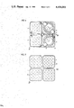
FIG. 3 shows a fuel assembly according to the invention in vertical section along III--III in FIG. 4, which shows a section along IV--IV in FIG. 3.
FIG. 5 shows the same fuel assembly in section and view along V--V in FIG. 6, and
FIG. 6 shows an upper part of the fuel assembly in section along VI--VI in FIG. 5.
FIG. 7 shows a section along VII--VII in FIG. 3.
FIG. 8 shows a section along VIII--VIII in FIG. 9, and
FIG. 9 shows a view from the plane IX--IX in FIG. 8.
DESCRIPTION OF PREFERRED EMBODIMENTS
The fuel assembly shown in the drawings has a vertical longitudinal axis and comprises 64 fuel rods 12, which are distributed among four different subassemblies. Each subassembly is surrounded by a wall system such as a substantially quadratic fuel channel 1. Each fuel channel 1 contains a plurality of spacers, not shown in the drawings, as well as one bottom plate 2, which supports the fuel rods of the subassembly. Each bottom plate 2 rests on a bottom frame 3, which is welded to a corresponding fuel channel 1 and which is constructed with a circular cylindrical inner surface. The four bottom frames 3 are supported by a distribution block 4, which is constructed with four hollow cylindrical outlet nozzles 5, each of the four bottom frames 3 surrounding one outlet nozzle with no mentionable play and being attached to the outlet nozzles by means of radially directed pins 6. Each outlet nozzle 5 is hydraulically connected, via an individual throttling channel 7, to a base 8 welded to the distribution block 4.
External wall surfaces of the fuel channels 1 define a vertical water channel 10 of cruciform cross-section, whereby each channel arm to a greater or smaller extent, is open in a radial direction. The four fuel channels 1, which each surround a fuel rod bundle, are connected at their upper ends and above the active portion of the core to an upper fuel channel portion 14 made with vertical extension H and arranged to surround all the fuel rods of the fuel assembly. An upper portion of each fuel channel 1 is mechanically connected to a central top tube 11.
The vertical channel 10 is hydraulically connected to a supply tube 13 at its lower portion. The upper fuel channel portion 14 has a substantially quadratic cross-section and, as shown in FIGS. 3 and 6, surrounds a top plate 15, which is made with a substantially quadratic frame 15', making contact with the inner side of the fuel channel portion 14, and with a plurality of horizontal bars 16 and 16', each of which is attached by one end to the frame 15' and by its other end to a central hollow cylinder 19 surrounding the central tube 11. Two horizontal arms 17 extend from a central portion of each of the bars 16 and 16' and are rigidly mechanically connected to the frame 15' by their outer ends. The freedom of movement of the fuel rods in an axially upward direction is restricted by means of portions of the bars 16 and 16' and of the arms 17 positioned above the fuel rods and by means of a plurality of horizontal projections 18 and 18', respectively, extending from the above-mentioned bars. The bars 16 have a greater cross-section than the bars 16' and are rigidly mechanically connected to a handle 20 for lifting the top plate 15.
Each of the fuel assemblies shown in the drawings is intended to be arranged, together with three similar fuel assemblies, in a module square in the top plate 21 of a reactor core. The control rod of the module is designated 27.
The fuel assembly shown in FIGS. 1-6 is provided with a distribution channel 22 for the sprinkling water which is supplied to the fuel assembly upon emergency cooling of the core. FIGS. 1 and 2 illustrate one case where it is of great importance to construct the fuel assembly with such a distribution channel. A plurality of sprinkling nozzles 23 are arranged, upon emergency cooling, to provide a sprinkling water cone 24 for one core module each. The sprinkling system is designed with respect to undivided fuel assemblies and in such a way that the sprinkling water cone 24 is evenly distributed between the four fuel assemblies of the module. However, when the fuel assembly is divided into four subassemblies, the amount of sprinkling water which is directly supplied to the subassemblies may be very unevenly distributed. In the case shown in FIGS. 1 and 2, thus, certain subassemblies will have no direct supply of sprinkling water at all. In a fuel assembly according to the invention, in such cases a relatively even distribution of the water of the sprinkling system is obtained between all subassemblies, which is obtained by using a water distribution channel.
In a water distribution channel 22 shown in FIGS. 1-6 the bottom of the channel is formed by a portion which is integral with the above-mentioned top plate 15, namely by the frame 15'. In addition, the channel is defined by radially inner and radially outer substantially vertical walls 25 and 26, respectively, which are attached to the inner edge and the outer edge, respectively, of the frame 15'. In one of the four corners of the fuel assembly and along a distance which corresponds to at least 10% of the circumference of the fuel assembly, as shown in FIG. 5, the radially inner wall 25 is folded inwards in such a way that the width k at the upper edge of the channel is at least 15%, preferably at least 25%, greater than the average channel width at the upper edge of the channel 22. When arranging the fuel assembly in the reactor core, the fuel assembly is preferably oriented in such a way that the radially inwardly extended portion of channel 22 will have as short a distance as possible to a vertical line through the nearest sprinkling nozzle. See FIGS. 1 and 5.
At corners of the channel 22 which are located diagonally in relation to the corner made with radially inwardly extended portion, the radially inner wall 25 is constructed with overflow portions, the lengths of which in the channel direction are designated a and in which the height of the wall 25 is at least 10% lower than its average height. See FIG. 5.
In case of emergency cooling, part of the sprinkling water will be supplied directly to the water distribution channel, whereafter a considerable part of the water of the channel is supplied via the overflow portions to the partial assembly which is located at the greatest distance from the sprinkling nozzle. Also the two adjacent partial assemblies may need to be supplied with water from the distribution channel, which can be performed through corresponding overflow portions which are constructed for a smaller total water flow to each partial assembly than the above-mentioned overflow portions with the extension a. It is also possible to supply the radially inner wall 25 with through holes in addition to or instead of the above-mentioned overflow portions.
The width k is preferably chosen in such a way that the radially inwardly extended channel portion, made with relatively great width, screens off the corresponding partial assembly from directly supplied sprinkling water to such an extent that this sprinkling water constitutes at the most one-fourth of the total flow of sprinkling water. The water received by said the radially inwardly extended channel portion is then supplied via the remainder of the distribution channel 22 to the partial assemblies which are less favoured as regards direct sprinkling, preferably in such a way that the flow of sprinkling water supplied to the fuel assembly is distributed with approximately one-fourth on each partial assembly.
On FIGS. 8 and 9, an upper portion of the fuel channel of the fuel assembly is designated 34. This portion surrounds all the fuel rods 31, each of which are inserted with their upper end pins into a through-hole of the top plate 33 of the fuel assembly. The top plate supports a water distribution channel 32 with substantially vertical walls 35 and 36 which, contrary to the corresponding walls shown in FIGS. 5 and 6, are interconnected by means of a bottom portion which is not integrated with the top plate of the fuel assembly, whereby this bottom portion together with the walls 35 and 36 form an internal channel 37 for sprinkling water. The wall 35 is made with vertical wall portions only, but it may also be made with an inwardly-bent portion in the same way as the corresponding wall 25 of the embodiment of the invention shown in FIG. 6. With a lower wall portion the wall 36 makes contact with the inner side of the fuel channel portion 34 with no mentionable play and is attached to the fuel channel by means of a plurality of horizontally directed screws, not shown in the drawing. At at least one of the sides of the fuel assembly, which are intended to face the control rod gap provided for a control rod 27, the wall 36 is made with a corbelled-out or radially outwardly extended portion 38 which protrudes into the control rod gap so that the width f of the corbelled-out portion constitutes at least 20%, preferably at least 30%, of the average width of the channel 37. The portion 38 collects a considerable part of the sprinkling water directed towards the control rod gap, so that also this water may be utilized for cooling the fuel assembly. The horizontal projection of the corbelled-out portion 38 lies substantially outside the fuel channel portion 34 and extends along at least 20% of the channel length. In the same way as the distribution channel 22, the channel 37 may be provided with several water outflows, and the inner channel wall may be bent inwardly along a minor portion of the total length of the channel.
The fuel assembly described in connection with the drawings is only one of many possible embodiments of a fuel assembly according to the invention. Thus, the distribution channel need not be made in the form of a closed loop, but may, for example, be made with only three corners and with two vertical end walls. In certain cases it is possible to achieve an even distribution of cooling water also if the cooling channel is made without overflow paths in the form of slots or holes. The subassemblies may also be constructed in such a way that a fuel channel, which surrounds all the fuel rods of the fuel assembly along their entire lengths, is divided into a plurality of compartments by means of a plurality of wall systems such as vertical partitions which, to a greater or smaller extent, prevent horizontal communication between the compartments, for example as disclosed in U.S. Pat. No. 3,164,530.

Claims (5)

What is claimed is:
1. A fuel assembly for a nuclear power reactor, comprising:
a plurality of groups of vertical fuel rods;
a plurality of wall systems, each wall system substantially surrounding one of said groups of fuel rods and extending along a greater part of the length of said fuel rods;
an annular fuel channel portion extending above said plurality of wall systems, a horizontal projection of said annular fuel channel portion surrounding all of the fuel rods of said fuel assembly, said annular fuel channel portion having an inner circumference;
a substantially horizontal water distribution channel extending above said groups of fuel rods as well as along and adjacent to most of said inner circumference, said water distribution channel being upwardly open and comprising means for receiving emergency cooling water supplied from a location above at least one of said groups of fuel rods and for distributing water so received to at least one of the remaining groups of fuel rods.
2. A fuel assembly according to claim 1, wherein said annular fuel channel portion has a substantially quadratic cross-section; each of said groups of fuel rods is arranged below a corresponding quadrant of said annular fuel channel portion; and said water distribution channel extends along the inner side of said annular fuel channel portion above a plurality of said quadrants, said water distribution channel in at least one quadrant comprising at least one water outflow for water to the corresponding group of fuel rods.
3. A fuel assembly according to claim 1, wherein said water distribution channel comprises a radially inner channel wall, a portion of which is inwardly-bent in such a way that the radial width of said water distribution channel at the upper edge of said inwardly-bent portion is at least 15% larger than the average channel width at the upper edge of the channel.
4. A fuel assembly according to claim 1, wherein said fuel assembly comprises a top plate arranged above said groups of fuel rods and said water distribution channel comprises a bottom portion at least a part of which comprises a peripheral portion of said top plate.
5. A fuel assembly according to claim 1, wherein said distribution channel comprises a wall portion which in use of said fuel assembly faces a control rod gap, said wall portion comprising a radially outwardly extended portion, the horizontal projection of said radially outwardly extended portion protruding substantially outside said horizontal projection of said annular fuel channel portion.
US06/315,604 1980-12-19 1981-10-30 Fuel assembly with a water distribution channel Expired - Fee Related US4454093A (en)

Applications Claiming Priority (2)

Application Number Priority Date Filing Date Title
SE8008986A SE424931B (en) 1980-12-19 1980-12-19 FUEL CARTRIDGE WITH WATER DISTRIBUTION CLEANER
SE8008986 1980-12-19

Publications (1)

Publication Number Publication Date
US4454093A true US4454093A (en) 1984-06-12

Family

ID=20342525

Family Applications (1)

Application Number Title Priority Date Filing Date
US06/315,604 Expired - Fee Related US4454093A (en) 1980-12-19 1981-10-30 Fuel assembly with a water distribution channel

Country Status (5)

Country Link
US (1) US4454093A (en)
JP (1) JPS57128883A (en)
DE (1) DE3148458A1 (en)
FI (1) FI70335C (en)
SE (1) SE424931B (en)

Cited By (9)

* Cited by examiner, † Cited by third party
Publication number Priority date Publication date Assignee Title
US4526744A (en) * 1981-05-15 1985-07-02 Ab Asea-Atom Fuel assembly for a boiling water reactor
EP0275873A1 (en) * 1987-01-12 1988-07-27 General Electric Company Cooled water rod (Loca conditions)
US5488644A (en) * 1994-07-13 1996-01-30 General Electric Company Spring assemblies for adjoining nuclear fuel rod containing ferrules and a spacer formed of the spring assemblies and ferrules
US5519746A (en) * 1994-11-28 1996-05-21 General Electric Company Large BWR fuel channel design
US5519747A (en) * 1994-10-04 1996-05-21 General Electric Company Apparatus and methods for fabricating spacers for a nuclear fuel rod bundle
US5546437A (en) * 1995-01-11 1996-08-13 General Electric Company Spacer for nuclear fuel rods
US5566217A (en) * 1995-01-30 1996-10-15 General Electric Company Reduced height spacer for nuclear fuel rods
US5675621A (en) * 1995-08-17 1997-10-07 General Electric Company Reduced height flat spring spacer for nuclear fuel rods
US20110075789A1 (en) * 2009-09-30 2011-03-31 Areva Np Module for Forming a Nuclear Fuel Assembly and Corresponding Nuclear Fuel Assembly

Citations (5)

* Cited by examiner, † Cited by third party
Publication number Priority date Publication date Assignee Title
US3920514A (en) * 1973-10-18 1975-11-18 Combustion Eng Emergency core cooling spray head
JPS5256298A (en) * 1975-10-31 1977-05-09 Toshiba Corp Cooling water pouring device for atomic pile emergency
US4123327A (en) * 1975-05-30 1978-10-31 Hitachi, Ltd. Fuel assembly for a nuclear reactor
JPS53148694A (en) * 1977-05-31 1978-12-25 Toshiba Corp Emergency cooling system of reactor core
JPS5438487A (en) * 1977-08-31 1979-03-23 Toshiba Corp Fuel assembly for reactor

Family Cites Families (1)

* Cited by examiner, † Cited by third party
Publication number Priority date Publication date Assignee Title
GB931676A (en) * 1960-09-05 1963-07-17 Atomic Energy Authority Uk Improvements in or relating to nuclear reactor core structures

Patent Citations (5)

* Cited by examiner, † Cited by third party
Publication number Priority date Publication date Assignee Title
US3920514A (en) * 1973-10-18 1975-11-18 Combustion Eng Emergency core cooling spray head
US4123327A (en) * 1975-05-30 1978-10-31 Hitachi, Ltd. Fuel assembly for a nuclear reactor
JPS5256298A (en) * 1975-10-31 1977-05-09 Toshiba Corp Cooling water pouring device for atomic pile emergency
JPS53148694A (en) * 1977-05-31 1978-12-25 Toshiba Corp Emergency cooling system of reactor core
JPS5438487A (en) * 1977-08-31 1979-03-23 Toshiba Corp Fuel assembly for reactor

Cited By (11)

* Cited by examiner, † Cited by third party
Publication number Priority date Publication date Assignee Title
US4526744A (en) * 1981-05-15 1985-07-02 Ab Asea-Atom Fuel assembly for a boiling water reactor
EP0275873A1 (en) * 1987-01-12 1988-07-27 General Electric Company Cooled water rod (Loca conditions)
US5488644A (en) * 1994-07-13 1996-01-30 General Electric Company Spring assemblies for adjoining nuclear fuel rod containing ferrules and a spacer formed of the spring assemblies and ferrules
US5519747A (en) * 1994-10-04 1996-05-21 General Electric Company Apparatus and methods for fabricating spacers for a nuclear fuel rod bundle
US5519746A (en) * 1994-11-28 1996-05-21 General Electric Company Large BWR fuel channel design
US5546437A (en) * 1995-01-11 1996-08-13 General Electric Company Spacer for nuclear fuel rods
US5566217A (en) * 1995-01-30 1996-10-15 General Electric Company Reduced height spacer for nuclear fuel rods
US5675621A (en) * 1995-08-17 1997-10-07 General Electric Company Reduced height flat spring spacer for nuclear fuel rods
US20110075789A1 (en) * 2009-09-30 2011-03-31 Areva Np Module for Forming a Nuclear Fuel Assembly and Corresponding Nuclear Fuel Assembly
EP2306464A1 (en) * 2009-09-30 2011-04-06 Areva NP Module for forming a nuclear fuel assembly and nuclear fuel assembly formed of a plurality of such modules
US8861671B2 (en) 2009-09-30 2014-10-14 Areva Np Module for forming a nuclear fuel assembly and corresponding nuclear fuel assembly

Also Published As

Publication number Publication date
SE8008986L (en) 1982-06-20
FI814068L (en) 1982-06-20
SE424931B (en) 1982-08-16
DE3148458A1 (en) 1982-07-15
FI70335B (en) 1986-02-28
FI70335C (en) 1986-09-15
JPS57128883A (en) 1982-08-10

Similar Documents

Publication Publication Date Title
CA1163024A (en) Fuel assembly with a water flow separated from the fuel rods
US4454093A (en) Fuel assembly with a water distribution channel
EP1407457B1 (en) Reduced pressure drop debris filter bottom nozzle for a fuel assembly of a nuclear reactor
US4526744A (en) Fuel assembly for a boiling water reactor
US3486973A (en) Breeder reactor
US4716013A (en) Nuclear reactor
DE2143494A1 (en) Pressurized water reactor
KR970004351B1 (en) Improved bwr assembly
US4632804A (en) Fuel assembly for a boiling water reactor
US5539793A (en) Lower tie plate debris catcher for a nuclear reactor
DE1293925B (en) Boiling water nuclear reactor
US5519746A (en) Large BWR fuel channel design
US5420901A (en) Lower tie plate debris catcher for a nuclear reactor
JPH022976A (en) Small fuel rod bundle for fuel assembly
US4127445A (en) Peripheral pin alignment system for fuel assemblies
US5251246A (en) Water rod concept without loss in active flow
US3888732A (en) Inlet for fuel assembly having finger control rods
EP0125326A1 (en) Nuclear reactor
JPH09184896A (en) Fuel bundle for boiling water reactor
US5255300A (en) Fuel assembly for boiling water reactors
JPH08114691A (en) Fuel assembly of boiling water reactor
JPH11505926A (en) Boiling water reactor fuel assemblies
US5617457A (en) Pressurized-water reactor with individually adapted pressure distribution in the coolant
US4514358A (en) Fuel assembly
US5089212A (en) Apparatus for controlling the power output of a nuclear reactor

Legal Events

Date Code Title Description
AS Assignment

Owner name: AB ASEA-ATOM, A CORP.OF SWEDEN

Free format text: ASSIGNMENT OF ASSIGNORS INTEREST.;ASSIGNORS:NYLUND, OLOV;ODE, BENGT;REEL/FRAME:003942/0976

Effective date: 19810917

Owner name: AB ASEA-ATOM, A CORP.OF, SWEDEN

Free format text: ASSIGNMENT OF ASSIGNORS INTEREST;ASSIGNORS:NYLUND, OLOV;ODE, BENGT;REEL/FRAME:003942/0976

Effective date: 19810917

REMI Maintenance fee reminder mailed
LAPS Lapse for failure to pay maintenance fees
STCH Information on status: patent discontinuation

Free format text: PATENT EXPIRED DUE TO NONPAYMENT OF MAINTENANCE FEES UNDER 37 CFR 1.362

FP Lapsed due to failure to pay maintenance fee

Effective date: 19880612