US4451705A - Call completion circuit and method - Google Patents
Call completion circuit and method Download PDFInfo
- Publication number
- US4451705A US4451705A US06/383,315 US38331582A US4451705A US 4451705 A US4451705 A US 4451705A US 38331582 A US38331582 A US 38331582A US 4451705 A US4451705 A US 4451705A
- Authority
- US
- United States
- Prior art keywords
- terminal
- calls
- accordance
- user
- completing
- Prior art date
- Legal status (The legal status is an assumption and is not a legal conclusion. Google has not performed a legal analysis and makes no representation as to the accuracy of the status listed.)
- Expired - Lifetime
Links
Images


Classifications
-
- H—ELECTRICITY
- H04—ELECTRIC COMMUNICATION TECHNIQUE
- H04M—TELEPHONIC COMMUNICATION
- H04M3/00—Automatic or semi-automatic exchanges
- H04M3/42—Systems providing special services or facilities to subscribers
- H04M3/50—Centralised arrangements for answering calls; Centralised arrangements for recording messages for absent or busy subscribers ; Centralised arrangements for recording messages
- H04M3/51—Centralised call answering arrangements requiring operator intervention, e.g. call or contact centers for telemarketing
- H04M3/523—Centralised call answering arrangements requiring operator intervention, e.g. call or contact centers for telemarketing with call distribution or queueing
-
- H—ELECTRICITY
- H04—ELECTRIC COMMUNICATION TECHNIQUE
- H04M—TELEPHONIC COMMUNICATION
- H04M3/00—Automatic or semi-automatic exchanges
- H04M3/42—Systems providing special services or facilities to subscribers
- H04M3/54—Arrangements for diverting calls for one subscriber to another predetermined subscriber
- H04M3/546—Arrangements for diverting calls for one subscriber to another predetermined subscriber in private branch exchanges
-
- Y—GENERAL TAGGING OF NEW TECHNOLOGICAL DEVELOPMENTS; GENERAL TAGGING OF CROSS-SECTIONAL TECHNOLOGIES SPANNING OVER SEVERAL SECTIONS OF THE IPC; TECHNICAL SUBJECTS COVERED BY FORMER USPC CROSS-REFERENCE ART COLLECTIONS [XRACs] AND DIGESTS
- Y10—TECHNICAL SUBJECTS COVERED BY FORMER USPC
- Y10S—TECHNICAL SUBJECTS COVERED BY FORMER USPC CROSS-REFERENCE ART COLLECTIONS [XRACs] AND DIGESTS
- Y10S379/00—Telephonic communications
- Y10S379/913—Person locator or person-specific
Definitions
- This invention relates to a communication system and more particularly to such a system where calls may be completed to a station either in accordance with the station identity or in accordance with the identity of a person currently using the system.
- ACD automatic call distributor
- each terminal position may be used for ACD as well as for regular calls, both incoming and outgoing.
- the users prior to handling an ACD call from any terminal, dial a special dial code, thereby entering their personal dial codes (PDC) into the central processor.
- PDC personal dial codes
- the current station location of each personal dial code is stored in status memory 16-2 in the station log in identification table (STA -- LID). From that point onward until a new dial code is entered, or until the PDC is either removed or entered on another terminal, calls may be placed to the terminal either by dialing the terminal identification number or by dialing the PDC number of the user.
- the system is also designed to allow intercom calls between terminals either in accordance with the identity of the terminal or in accordance with the identity of a person, not necessarily an ACD agent, presently using that terminal.
- FIG. 1 shows a pictorial view of a combined ACD and communication system
- FIG. 2 shows a pictorial view of one station set to which a headset has been connected for ACD operation
- FIG. 3 shows in more detail a schematic of the transmission path and control circuitry for ACD operation
- FIGS. 4 and 5 show flow charts of the operation of the call completion arrangement.
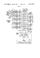
- FIG. 1 shows a block diagram of such a system which combines the usual key system features (hold, visual indication, etc.) with many features only recently available.
- Call processing in the system is under the control of processor 15 in common control 14.
- Each station such as Station S1, and line port, such as 13-1, is scanned to detect any changes in status.
- the processor per instructions in the stored program in memory 16 translates these changes into system commands.
- the system also generates commands via a bidirectional data bus 101 to the multibutton electronic telephone (MET) set, shown in detail in FIG. 2, to light the light emitting diodes (LEDs) and ring the tone ringer associated with the MET set. All of the MET sets provide TOUCH-TONE dialing, tone ringing, and LED indications. The LED indicators will be discussed hereinafter.
- the tone ringer provides two distinctive audible signals--low-pitched tone ringing to indicate incoming CO calls and high-pitched tone ringing to indicate incoming station-to-station (intercom) calls.
- Nonbutton key sets can be used as station positions where only station-to-station (intercom) calling and/or outward dialing, via dial access pooled facilities or a central answer position, are required.
- the first (lower) 4 buttons on each MET station set are always the same. They are: Hold, +/-, and two system access buttons, each associated with the intercom number of the particular station.
- the +/- feature is described in the aforementioned patent of Fenton et al.
- the system access buttons are used to receive calls from other stations within the communication system (intercom) and to originate such calls or to access system facilities such as lines, paging ports, etc. Incoming calls may terminate on either system access button depending on their busy/idle status.
- buttons are also used in conferencing and call transfer features such as described in the aforementioned patent of Nahabedian et al.
- the remainder of the buttons on the MET station sets are flexible buttons and can be assigned to any of the button-activated station or answering position features, such as call coverage, as shown in the aforementioned patent of Fenton et al; and pooled line treatment, as shown in the aforementioned patent of Allison et al.
- FIG. 1 there are three pairs of wires coming out of the electronic key telephone set to the interface unit: T&R, data in, data out.
- the T&R pairs are connected to switching network 11.
- switching network 11 In the example shown a space division network with n links is shown. It may be replaced by a time division with n time slots.
- the data link between the set and the processor is used to transmit information to the processor which will configure the switching network and send LED control signals back to the telephone sets accordingly.
- System facilities such as system facility 10, is understood to include origination registers, tone circuits, stations, lines, trunks or any port which can be communication coupled to a link of the network.
- Common control 14 consists of processor 15, interface units 17 and 18 and memory 16.
- the memory unit consists of a program store 16-1, and a data store 16-2.
- the data store is subdivided into the following:
- Translation which contains the hardware configuration data. For example, the button assignments and station class of service.
- a typical common control processor works on a 25 ms work cycle.
- a high level executive program, TSK -- DSP controls the order of tasks executed in a work cycle.
- a hardware real time interrupt is received by the processor.
- the interrupt handling routine sets a flag and returns to the interrupted task which in turn will relinquish control to TSK -- DSP control, as soon as it reaches a convenient break point.
- the task dispenser decides which task is to be executed next according to a schedule. Basically these tasks fall into three categories:
- Scan Scan for physical changes (e.g., a new button depression by a station). If a change is detected and confirmed, it will be stored in a temporary buffer to be processed later.
- This feature provides a red I-Use LED, such as LED 212, FIG. 2, associated with each line access button (tracking feature, system access, pooled facilities access, personal line access, automatic intercom, and call coverage).
- line access button tracking feature, system access, pooled facilities access, personal line access, automatic intercom, and call coverage.
- this LED indicates the line to which the station is connected.
- on-hook this LED indicates the line to which the station would be connected upon going off-hook.
- Call status indications are given by means of a green status LED such as LED 211, FIG. 2, associated with each line access button (tracking feature, system access, pooled facilities access, personal line access, automatic intercom, and call coverage).
- the status LED flashes (500 ms on, 500 ms off) during the ringing state, lights steadily during the busy state, and winks (450 mn on, 50 ms off) during the hold state.
- Automatic intercom is provided by a 2-way point-to-point voice path between two designated MET stations with automatic signaling of the called station.
- the calling station user Upon depressing an automatic intercom button and going off-hook, the calling station user hears ringback and the called station receives the standard station-to-station distinctive alert.
- the status LED associated with the automatic intercom button is steady at the calling station and flashing at the called station.
- the called station user may anser the call by depressing the automatic intercom button and going off-hook.
- Distinctive alerting allows the station user to distinguish between incoming CO calls and incoming station-to-station calls.
- One tone is used as the alert for incoming CO calls extended by the attendant or on a personal CO line.
- a second higher frequency tone serves as the audible alert for station-to-station (intercom) calls.
- Each of these signals has a repetition period of 4 seconds with a 1-second on-time and a 3-second off-time. These tones are controlled by data sent to each station over the data bus.
- This feature provides a communication channel between a station user and a dedicated outside line via the switching network. Unlike pooled facilities, which can also be accessed by dial codes, personal lined are only accessible by means of a dedicated access button, which provides incoming as well as outgoing service.
- a personal line may be shared by as many as eight stations by providing each of these stations with the associated personal line access button. Because of the conference limit, however, no more than five parties may be on any given call. Any attempt by a sixth station to bridge on will be ignored (i.e., handled as an excluded station). Full common audible ringing may be provided optionally to any or all stations sharing the line. Control of the line with respect to call coverage features is available to only one designated station.
- the station user Upon depressing a pooled facilities access button and going off-hook, the station user is connected to an idle line facility belonging to a common pool of outside lines (e.g., CO, FX, WATS, etc.).
- a common pool of outside lines e.g., CO, FX, WATS, etc.
- the status and I-Use LEDs associated with the pooled facilities access button will light steadily, and the station user will be free to complete the call. If no idle facilities are available (facilities by indication), a user's attempt to originate will simply be denied and the I-use indication will be extinguished.
- a station requiring button access to several line pools may be equipped with a separate access button for each of the required pools.
- Each line pool may optionally be assigned a dial access code, permitting selection of an idle line from the pool by dialing the code after having originated on a system access button. Reorder tone will be returned if no lines in the selected pool are idle.
- This feature keeps the station user informed of the availability of any of the idle lines in any pooled facility group accessible to the station by means of a pooled facility access button.
- the status LED associated with a pooled facility access button will indicate busy whenever all the lines within the associated pool are busy, as well as when a line in the pool is being used at a given station.
- This feature automatically connects the station user, upon going off-hook, to the line designated as the prime line.
- a station user may override this preference by preselecting another line or depressing the HOLD button prior to going off-hook. If ringing line preference is also in effect at a given station, that feature takes precedence.
- this feature automatically selects a line access button which has a call ringing the station set. If two or more lines are ringing simultaneously, the station user is connected to the first line to start ringing. If the user wishes to use a different line, the line must be preselected prior to going off-hook. Once a station is off-hook, ringing line preference will be canceled on any subsequent call until the user returns to the on-hook state. If ringing ceases while the station user is still on-hook, line preference reverts to whichever option is applicable--no line or prime line.
- This feature allows a station user to directly dial other stations within the system without the assistance of the attendant. This is accomplished by selecting an idle system access button and dialing the intercom code of the desired station.
- the processor (FIG. 1, item 15) takes the information in (b) and uses it to update the instantaneous information in (a).
- the processor Periodically in the scan cycle, the processor takes the information in (a) and (d) and assembles it into a single long message for a single station in the format required by the MET station set. That message is stored in status memory 16-2 in the station lamp scan output table (SLSO). This data is transmitted to the MET using the data interface (FIG. 1, item 17). The MET returns to the processor, via the data interface, the instantaneous state of its switch-hook and buttons, which is stored in status memory 16-2 in the data structure station MET input/output table (SEIO).
- SEIO data structure station MET input/output table
- the returned data is compared with that in (c) above and if there are any changes, records these in a temporary buffer for that station in 16-2 called station change/timing byte table (SCTB).
- SCTB station change/timing byte table
- the processor program Whenever the processor program wishes to turn on or off an LED on a MET, or set it to wink or flash, it writes the appropriate bits into the status memory described in (b) and this function will automatically occur as a consequence of the two periodic actions described above.
- SBID station button identification
- This information is coded in numerical forms, e.g., a value of 1 identifies a personal line button, a value of 2 identifies a pooled line button, 3 identifies a track button, etc.
- a speech-type button e.g., system access, auto-intercom, personal line, pooled line, call coverage, etc.
- a speech-type button e.g., system access, auto-intercom, personal line, pooled line, call coverage, etc.
- This information is stored in the status data memory (16-2 in FIG. 1) coded in numerical forms.
- the same data format is used although the valid states may reduce to 2 (busy and idle).
- the scan routine in the system detects and reports a button push by the MET user to a buffered area to wait for the process routines to process.
- the button identification information, SBID, stored in 16-2 is first checked, then the button status information stored in 16-2 is checked.
- the processor is thus able to interpret the button push to a specific user command and uses the proper programs stored in 16-1 to process the change. For example, button selection of
- an idle (from SELP or SELS) speech-type (from SBID) button implies call origination requiring the associated facilities.
- a ringing (from SEIO or SELS) speech-type (from SBID) button implies answer a ringing call.
- FIG. 4 shows an overview of the three basic decisions which must be made any time a user decides to place a telephone call.
- Process 402 represents the condition where the agent or other communication system user wishes to log in using the personal dial code (PDC). To do this, the user operates the asterisk (*) key twice followed by the three-digit personal dial code repeated twice.
- PDC personal dial code
- Process 403 represents a situation where the user wishes to place a call to a particular station by using the intercom number of the station, and the situation in process 404 depicts the situation where the user wishes to place a call to another party by using the personal dial code of that called party.
- the user would operate the asterisk and pound (number) buttons (*#) followed by the three-digit number of the called party.
- the physical location of the terminal is not important, but rather the call is directed to the terminal where the called party is currently located.
- process 501 the user presses the system access button on a telephone station set and dials the desired digits. If the first digit dialed is not an asterisk (*), then box 502 directs the call to process 504 where it is determined that this is not a login or a call by personal dial code and thus no further action is necessary. If the first digit dialed is an asterisk (*), then process 503 waits for the second digit. If the second digit is not an asterisk (*) or pound (#), then again the call is treated as a regular intercom dial call via process 504.
- the system determines that the user is logging into this terminal and process 505 then accepts the three-digit personal dial code and process 506 then accepts three more digits which should be identical to the first three digits.
- Process 507 compares these two sets of digits, and if they are not the same, provides reorder tone via process 510 to the user. However, if both sets of PDC digits match, then process 507 calls process 508 which in turn updates the system records in the STA -- LID table in 16-2 to show that the personal identification code is logged in at the terminal from which the digits were entered.
Abstract
Description
Claims (8)
Priority Applications (7)
| Application Number | Priority Date | Filing Date | Title |
|---|---|---|---|
| US06/383,315 US4451705A (en) | 1982-05-28 | 1982-05-28 | Call completion circuit and method |
| EP19830902016 EP0109432A4 (en) | 1982-05-28 | 1983-05-09 | Call completion circuit and method. |
| PCT/US1983/000695 WO1983004358A1 (en) | 1982-05-28 | 1983-05-09 | Call completion circuit and method |
| AU17028/83A AU546157B2 (en) | 1982-05-28 | 1983-05-09 | Call completion circuit and method |
| CA000428194A CA1193699A (en) | 1982-05-28 | 1983-05-16 | Call completion circuit and method |
| IT21325/83A IT1170299B (en) | 1982-05-28 | 1983-05-26 | CALL COMPLETION CIRCUIT |
| GB08314807A GB2122846B (en) | 1982-05-28 | 1983-05-27 | Call completion circuit and method |
Applications Claiming Priority (1)
| Application Number | Priority Date | Filing Date | Title |
|---|---|---|---|
| US06/383,315 US4451705A (en) | 1982-05-28 | 1982-05-28 | Call completion circuit and method |
Publications (1)
| Publication Number | Publication Date |
|---|---|
| US4451705A true US4451705A (en) | 1984-05-29 |
Family
ID=23512583
Family Applications (1)
| Application Number | Title | Priority Date | Filing Date |
|---|---|---|---|
| US06/383,315 Expired - Lifetime US4451705A (en) | 1982-05-28 | 1982-05-28 | Call completion circuit and method |
Country Status (7)
| Country | Link |
|---|---|
| US (1) | US4451705A (en) |
| EP (1) | EP0109432A4 (en) |
| AU (1) | AU546157B2 (en) |
| CA (1) | CA1193699A (en) |
| GB (1) | GB2122846B (en) |
| IT (1) | IT1170299B (en) |
| WO (1) | WO1983004358A1 (en) |
Cited By (30)
| Publication number | Priority date | Publication date | Assignee | Title |
|---|---|---|---|---|
| US4626627A (en) * | 1983-10-07 | 1986-12-02 | Teledex | Telephone line selector for use with a PBX |
| US4694483A (en) * | 1986-06-02 | 1987-09-15 | Innings Telecom Inc. | Computerized system for routing incoming telephone calls to a plurality of agent positions |
| US4893301A (en) * | 1988-06-27 | 1990-01-09 | Teknekron Infoswitch Corporation | Automatic call distribution (ACD) switching system having distributed processing capability |
| US5025468A (en) * | 1989-05-04 | 1991-06-18 | Harris Corporation | Computerized system for incoming calls |
| US5043881A (en) * | 1985-04-03 | 1991-08-27 | Hitachi, Ltd. | Session control method for rewriting information in a session control device in an interactive processing system |
| US5267307A (en) * | 1988-06-13 | 1993-11-30 | Canon Kabushiki Kaisha | Communication apparatus |
| US5392346A (en) * | 1992-02-25 | 1995-02-21 | At&T Corp. | Mobile log-in capability featuring fixed physical (terminal-dependent) translations and portable logical (user-dependent) translations |
| US5452348A (en) * | 1993-02-12 | 1995-09-19 | Adams; David J. | Automatic call distribution system with emergency conferencing and method |
| US5463685A (en) * | 1992-04-01 | 1995-10-31 | At&T Ipm Corp. | Network based outbound call management |
| US5499342A (en) * | 1987-11-20 | 1996-03-12 | Hitachi, Ltd. | System for dynamically switching logical sessions between terminal device and a processor which stops its operation to another working processor under control of communication control processor |
| US5541992A (en) * | 1992-06-11 | 1996-07-30 | Hitachi, Ltd. | System for connecting an incoming call to a selected one of a number of extensions |
| US5703930A (en) * | 1991-03-11 | 1997-12-30 | At&T Corp. | Personal mobile communication system with call bridging |
| US5712909A (en) * | 1994-08-25 | 1998-01-27 | Kabushiki Kaisha Toshiba | Key telephone apparatus with automatic call distribution function |
| US5757897A (en) * | 1994-12-07 | 1998-05-26 | Digital Techniques, Inc. | Telephone switch call control unit |
| US5815566A (en) * | 1991-10-10 | 1998-09-29 | Executone Information Systems, Inc. | Apparatus and method for dynamic inbound/outbound call management and for scheduling appointments |
| US5864617A (en) * | 1996-03-26 | 1999-01-26 | British Telecommunications Public Limited Company | Call queuing and distribution |
| US5884039A (en) * | 1993-10-01 | 1999-03-16 | Collaboration Properties, Inc. | System for providing a directory of AV devices and capabilities and call processing such that each participant participates to the extent of capabilities available |
| US6011844A (en) * | 1998-06-19 | 2000-01-04 | Callnet Communications | Point-of-presence call center management system |
| US6324276B1 (en) | 1999-02-12 | 2001-11-27 | Telera, Inc. | Point-of-presence call center management system |
| DE19709214C2 (en) * | 1996-03-11 | 2001-12-06 | Mitel Corp | Procedure for forwarding calls in a telephone system |
| US20020052199A1 (en) * | 2000-10-30 | 2002-05-02 | Mukesh Sundaram | Call center management for wireless access network |
| US20020124051A1 (en) * | 1993-10-01 | 2002-09-05 | Ludwig Lester F. | Marking and searching capabilities in multimedia documents within multimedia collaboration networks |
| US6512825B1 (en) | 1999-07-13 | 2003-01-28 | Interactive Intelligence, Inc. | Queue-based distinctive ringing in a call center system |
| EP1328107A1 (en) * | 2002-01-11 | 2003-07-16 | Siemens Aktiengesellschaft | Method to establish a service providing program, corresponding units and corresponding pogram |
| US6898620B1 (en) | 1996-06-07 | 2005-05-24 | Collaboration Properties, Inc. | Multiplexing video and control signals onto UTP |
| US20050144284A1 (en) * | 1997-11-04 | 2005-06-30 | Collaboration Properties, Inc. | Scalable networked multimedia system and applications |
| EP1620982A2 (en) * | 2003-05-02 | 2006-02-01 | Cisco Technology, Inc. | Method and system for automatic contact distribution utilizing presence detection |
| US7185054B1 (en) | 1993-10-01 | 2007-02-27 | Collaboration Properties, Inc. | Participant display and selection in video conference calls |
| US20070093672A1 (en) * | 2005-10-21 | 2007-04-26 | Catalytic Distillation Technologies | Process for producing organic carbonates |
| US8290526B2 (en) * | 2011-03-02 | 2012-10-16 | Sonetics Corporation | Wireless ground support systems |
Families Citing this family (4)
| Publication number | Priority date | Publication date | Assignee | Title |
|---|---|---|---|---|
| GB2153631A (en) * | 1984-01-20 | 1985-08-21 | Teradyne Inc | Automatically processing incoming calls |
| GB2198910B (en) * | 1986-12-17 | 1990-09-05 | Stanley Electric Co Ltd | Telephone exchange system |
| CA2103204C (en) * | 1992-11-17 | 2002-11-12 | Daniel F. Baker | Call distributor with automatic preannouncement system and method |
| JP4346519B2 (en) | 2004-07-13 | 2009-10-21 | 株式会社東芝 | Telephone system, communication control method thereof, and application control apparatus |
Citations (17)
| Publication number | Priority date | Publication date | Assignee | Title |
|---|---|---|---|---|
| US3660611A (en) * | 1970-06-05 | 1972-05-02 | Bell Telephone Labor Inc | Program controlled key telephone system for automatic selection of a prime line |
| US3890473A (en) * | 1973-04-19 | 1975-06-17 | Gte International Inc | Operator display arrangements |
| US3991279A (en) * | 1975-05-23 | 1976-11-09 | Bell Telephone Laboratories, Incorporated | Monobus interface circuit |
| US3991280A (en) * | 1975-05-23 | 1976-11-09 | Bell Telephone Laboratories, Incorporated | Monobus variable resistance transmission circuit |
| US4046972A (en) * | 1976-10-27 | 1977-09-06 | Bell Telephone Laboratories, Incorporated | Key telephone station set circuit |
| US4048452A (en) * | 1976-05-28 | 1977-09-13 | Bell Telephone Laboratories, Incorporated | Automatic call distribution system |
| US4109113A (en) * | 1977-10-31 | 1978-08-22 | Bell Telephone Laboratories, Incorporated | Communication system optimized pooled line arrangement |
| US4110566A (en) * | 1977-10-27 | 1978-08-29 | Bell Telephone Laboratories, Incorporated | Switching network control arrangement |
| US4125748A (en) * | 1977-10-31 | 1978-11-14 | Bell Telephone Laboratories, Incorporated | Communication system call transfer arrangement |
| US4150257A (en) * | 1977-10-31 | 1979-04-17 | Bell Telephone Laboratories, Incorporated | Communication system call coverage arrangements |
| US4150259A (en) * | 1977-10-31 | 1979-04-17 | Bell Telephone Laboratories, Incorporated | Communication system conferencing arrangement |
| US4197430A (en) * | 1978-09-15 | 1980-04-08 | Bell Telephone Laboratories, Incorporated | Operator service position system |
| US4286118A (en) * | 1979-07-02 | 1981-08-25 | Solid State Systems, Inc. | Data distribution system for private automatic branch exchange |
| US4289934A (en) * | 1979-04-25 | 1981-09-15 | Wescom Switching Inc. | Integrated automatic call distribution facility and PBX system |
| US4291199A (en) * | 1979-03-28 | 1981-09-22 | Bell Telephone Laboratories, Incorporated | Communication system tracking arrangement |
| US4296282A (en) * | 1980-06-30 | 1981-10-20 | Bell Telephone Laboratories, Incorporated | Incoming call identification arrangement |
| US4313035A (en) * | 1980-01-18 | 1982-01-26 | Bell Telephone Laboratories, Incorporated | Method of providing person locator service |
Family Cites Families (4)
| Publication number | Priority date | Publication date | Assignee | Title |
|---|---|---|---|---|
| JPS6010470B2 (en) * | 1978-02-25 | 1985-03-18 | 日本電信電話公社 | Personal calling phone system |
| DE2912764C3 (en) * | 1979-03-30 | 1981-12-24 | Siemens AG, 1000 Berlin und 8000 München | Method for centrally controlled telecommunications switching systems, in particular telephone branch exchange switching systems, with switching stations |
| JPS56111366A (en) * | 1980-02-08 | 1981-09-03 | Hitachi Ltd | Absence transfer system |
| DE3036380A1 (en) * | 1980-09-26 | 1982-05-13 | Siemens AG, 1000 Berlin und 8000 München | COMMUNICATION SYSTEM, ESPECIALLY TELEPHONE SYSTEM |
-
1982
- 1982-05-28 US US06/383,315 patent/US4451705A/en not_active Expired - Lifetime
-
1983
- 1983-05-09 AU AU17028/83A patent/AU546157B2/en not_active Expired
- 1983-05-09 WO PCT/US1983/000695 patent/WO1983004358A1/en not_active Application Discontinuation
- 1983-05-09 EP EP19830902016 patent/EP0109432A4/en not_active Withdrawn
- 1983-05-16 CA CA000428194A patent/CA1193699A/en not_active Expired
- 1983-05-26 IT IT21325/83A patent/IT1170299B/en active
- 1983-05-27 GB GB08314807A patent/GB2122846B/en not_active Expired
Patent Citations (17)
| Publication number | Priority date | Publication date | Assignee | Title |
|---|---|---|---|---|
| US3660611A (en) * | 1970-06-05 | 1972-05-02 | Bell Telephone Labor Inc | Program controlled key telephone system for automatic selection of a prime line |
| US3890473A (en) * | 1973-04-19 | 1975-06-17 | Gte International Inc | Operator display arrangements |
| US3991279A (en) * | 1975-05-23 | 1976-11-09 | Bell Telephone Laboratories, Incorporated | Monobus interface circuit |
| US3991280A (en) * | 1975-05-23 | 1976-11-09 | Bell Telephone Laboratories, Incorporated | Monobus variable resistance transmission circuit |
| US4048452A (en) * | 1976-05-28 | 1977-09-13 | Bell Telephone Laboratories, Incorporated | Automatic call distribution system |
| US4046972A (en) * | 1976-10-27 | 1977-09-06 | Bell Telephone Laboratories, Incorporated | Key telephone station set circuit |
| US4110566A (en) * | 1977-10-27 | 1978-08-29 | Bell Telephone Laboratories, Incorporated | Switching network control arrangement |
| US4125748A (en) * | 1977-10-31 | 1978-11-14 | Bell Telephone Laboratories, Incorporated | Communication system call transfer arrangement |
| US4109113A (en) * | 1977-10-31 | 1978-08-22 | Bell Telephone Laboratories, Incorporated | Communication system optimized pooled line arrangement |
| US4150257A (en) * | 1977-10-31 | 1979-04-17 | Bell Telephone Laboratories, Incorporated | Communication system call coverage arrangements |
| US4150259A (en) * | 1977-10-31 | 1979-04-17 | Bell Telephone Laboratories, Incorporated | Communication system conferencing arrangement |
| US4197430A (en) * | 1978-09-15 | 1980-04-08 | Bell Telephone Laboratories, Incorporated | Operator service position system |
| US4291199A (en) * | 1979-03-28 | 1981-09-22 | Bell Telephone Laboratories, Incorporated | Communication system tracking arrangement |
| US4289934A (en) * | 1979-04-25 | 1981-09-15 | Wescom Switching Inc. | Integrated automatic call distribution facility and PBX system |
| US4286118A (en) * | 1979-07-02 | 1981-08-25 | Solid State Systems, Inc. | Data distribution system for private automatic branch exchange |
| US4313035A (en) * | 1980-01-18 | 1982-01-26 | Bell Telephone Laboratories, Incorporated | Method of providing person locator service |
| US4296282A (en) * | 1980-06-30 | 1981-10-20 | Bell Telephone Laboratories, Incorporated | Incoming call identification arrangement |
Cited By (82)
| Publication number | Priority date | Publication date | Assignee | Title |
|---|---|---|---|---|
| US6459781B1 (en) * | 1919-08-25 | 2002-10-01 | Kabushiki Kaisha Toshiba | Key telephone apparatus with call distribution function |
| US4626627A (en) * | 1983-10-07 | 1986-12-02 | Teledex | Telephone line selector for use with a PBX |
| US5043881A (en) * | 1985-04-03 | 1991-08-27 | Hitachi, Ltd. | Session control method for rewriting information in a session control device in an interactive processing system |
| US4694483A (en) * | 1986-06-02 | 1987-09-15 | Innings Telecom Inc. | Computerized system for routing incoming telephone calls to a plurality of agent positions |
| US5499342A (en) * | 1987-11-20 | 1996-03-12 | Hitachi, Ltd. | System for dynamically switching logical sessions between terminal device and a processor which stops its operation to another working processor under control of communication control processor |
| US5267307A (en) * | 1988-06-13 | 1993-11-30 | Canon Kabushiki Kaisha | Communication apparatus |
| US4893301A (en) * | 1988-06-27 | 1990-01-09 | Teknekron Infoswitch Corporation | Automatic call distribution (ACD) switching system having distributed processing capability |
| US5025468A (en) * | 1989-05-04 | 1991-06-18 | Harris Corporation | Computerized system for incoming calls |
| US5703930A (en) * | 1991-03-11 | 1997-12-30 | At&T Corp. | Personal mobile communication system with call bridging |
| US6148193A (en) * | 1991-03-11 | 2000-11-14 | At&T Corp. | Personal mobile communication system with call bridging |
| US6463277B1 (en) | 1991-03-11 | 2002-10-08 | At&T Corp. | Personal mobile communication system with call bridging |
| US5815566A (en) * | 1991-10-10 | 1998-09-29 | Executone Information Systems, Inc. | Apparatus and method for dynamic inbound/outbound call management and for scheduling appointments |
| US5392346A (en) * | 1992-02-25 | 1995-02-21 | At&T Corp. | Mobile log-in capability featuring fixed physical (terminal-dependent) translations and portable logical (user-dependent) translations |
| US5463685A (en) * | 1992-04-01 | 1995-10-31 | At&T Ipm Corp. | Network based outbound call management |
| US5541992A (en) * | 1992-06-11 | 1996-07-30 | Hitachi, Ltd. | System for connecting an incoming call to a selected one of a number of extensions |
| US5563940A (en) * | 1992-06-11 | 1996-10-08 | Hitachi, Ltd. | System for connecting an incoming call to a selected one of a number of extensions |
| US5815564A (en) * | 1992-06-11 | 1998-09-29 | Hitachi, Ltd. | System for connecting an incoming call to a selected one of a number of extensions |
| US5452348A (en) * | 1993-02-12 | 1995-09-19 | Adams; David J. | Automatic call distribution system with emergency conferencing and method |
| US20070083596A1 (en) * | 1993-10-01 | 2007-04-12 | Collaboration Properties, Inc. | Storing and Accessing Media Files |
| US20070088782A1 (en) * | 1993-10-01 | 2007-04-19 | Collaboration Properties, Inc. | Storage and Playback of Media Files |
| US7908320B2 (en) | 1993-10-01 | 2011-03-15 | Pragmatus Av Llc | Tracking user locations over multiple networks to enable real time communications |
| US5884039A (en) * | 1993-10-01 | 1999-03-16 | Collaboration Properties, Inc. | System for providing a directory of AV devices and capabilities and call processing such that each participant participates to the extent of capabilities available |
| US7831663B2 (en) | 1993-10-01 | 2010-11-09 | Pragmatus Av Llc | Storage and playback of media files |
| US6212547B1 (en) | 1993-10-01 | 2001-04-03 | Collaboration Properties, Inc. | UTP based video and data conferencing |
| US6237025B1 (en) | 1993-10-01 | 2001-05-22 | Collaboration Properties, Inc. | Multimedia collaboration system |
| US7822813B2 (en) | 1993-10-01 | 2010-10-26 | Ludwig Lester F | Storing and accessing media files |
| US7730132B2 (en) | 1993-10-01 | 2010-06-01 | Ludwig Lester F | Storing and accessing media files |
| US6343314B1 (en) | 1993-10-01 | 2002-01-29 | Collaboration Properties, Inc. | Remote participant hold and disconnect during videoconferencing |
| US6351762B1 (en) | 1993-10-01 | 2002-02-26 | Collaboration Properties, Inc. | Method and system for log-in-based video and multimedia calls |
| US7487210B2 (en) | 1993-10-01 | 2009-02-03 | Avistar Communications Corporation | Method for managing real-time communications |
| US7444373B2 (en) | 1993-10-01 | 2008-10-28 | Avistar Communications Corporation | Wireless real-time communication |
| US6426769B1 (en) | 1993-10-01 | 2002-07-30 | Collaboration Properties, Inc. | High-quality switched analog video communications over unshielded twisted pair |
| US6437818B1 (en) | 1993-10-01 | 2002-08-20 | Collaboration Properties, Inc. | Video conferencing on existing UTP infrastructure |
| US7441001B2 (en) | 1993-10-01 | 2008-10-21 | Avistar Communications Corporation | Real-time wide-area communications between ports |
| US20020124051A1 (en) * | 1993-10-01 | 2002-09-05 | Ludwig Lester F. | Marking and searching capabilities in multimedia documents within multimedia collaboration networks |
| US7437411B2 (en) | 1993-10-01 | 2008-10-14 | Avistar Communications Corporation | Communication of a selected type over a wide area network |
| US7437412B2 (en) | 1993-10-01 | 2008-10-14 | Avistar Communications Corporation | Real-time communication of a selected type |
| US7433921B2 (en) | 1993-10-01 | 2008-10-07 | Avistar Communications Corporation | System for real-time communication between plural users |
| US6583806B2 (en) | 1993-10-01 | 2003-06-24 | Collaboration Properties, Inc. | Videoconferencing hardware |
| US6594688B2 (en) | 1993-10-01 | 2003-07-15 | Collaboration Properties, Inc. | Dedicated echo canceler for a workstation |
| US7421470B2 (en) | 1993-10-01 | 2008-09-02 | Avistar Communications Corporation | Method for real-time communication between plural users |
| US20030158901A1 (en) * | 1993-10-01 | 2003-08-21 | Collaboration Properties, Inc. | UTP based video conferencing |
| US20030187940A1 (en) * | 1993-10-01 | 2003-10-02 | Collaboration Properties, Inc. | Teleconferencing employing multiplexing of video and data conferencing signals |
| US6789105B2 (en) | 1993-10-01 | 2004-09-07 | Collaboration Properties, Inc. | Multiple-editor authoring of multimedia documents including real-time video and time-insensitive media |
| US7412482B2 (en) | 1993-10-01 | 2008-08-12 | Avistar Communications Corporation | System for managing real-time communications |
| US7398296B2 (en) | 1993-10-01 | 2008-07-08 | Avistar Communications Corporation | Networked audio communication over two networks |
| US6959322B2 (en) | 1993-10-01 | 2005-10-25 | Collaboration Properties, Inc. | UTP based video conferencing |
| US20070168426A1 (en) * | 1993-10-01 | 2007-07-19 | Collaboration Properties, Inc. | Storing and Accessing Media Files |
| US20060041616A1 (en) * | 1993-10-01 | 2006-02-23 | Collaboration Properties, Inc. | Audio communications using devices with different capabilities |
| US20060041617A1 (en) * | 1993-10-01 | 2006-02-23 | Collaboration Properties, Inc. | Log-in based communications plus two data types |
| US20060059266A1 (en) * | 1993-10-01 | 2006-03-16 | Collaboration Properties, Inc. | Registration based addressing over multiple networks with digital audio communication |
| US20060064461A1 (en) * | 1993-10-01 | 2006-03-23 | Collaboration Properties, Inc. | Using login-based addressing to communicate with listed users |
| US20060075121A1 (en) * | 1993-10-01 | 2006-04-06 | Collaboration Properties, Inc. | Registration based addressing and call handles to establish communication |
| US7054904B2 (en) | 1993-10-01 | 2006-05-30 | Collaboration Properties, Inc. | Marking and searching capabilities in multimedia documents within multimedia collaboration networks |
| US7152093B2 (en) | 1993-10-01 | 2006-12-19 | Collaboration Properties, Inc. | System for real-time communication between plural users |
| US7185054B1 (en) | 1993-10-01 | 2007-02-27 | Collaboration Properties, Inc. | Participant display and selection in video conference calls |
| US20070078932A1 (en) * | 1993-10-01 | 2007-04-05 | Collaboration Properties, Inc. | Audio Communication with Login Location Addressing |
| US20070078930A1 (en) * | 1993-10-01 | 2007-04-05 | Collaboration Properties, Inc. | Method for Managing Real-Time Communications |
| US20070078933A1 (en) * | 1993-10-01 | 2007-04-05 | Collaboration Properties, Inc. | Networked Audio Communication Over Two Networks |
| US20070078931A1 (en) * | 1993-10-01 | 2007-04-05 | Collaboration Properties, Inc. | System for Managing Real-Time Communications |
| US7206809B2 (en) | 1993-10-01 | 2007-04-17 | Collaboration Properties, Inc. | Method for real-time communication between plural users |
| US20070083593A1 (en) * | 1993-10-01 | 2007-04-12 | Collaboration Properties, Inc. | Wireless Networked Audio Communication |
| US20070083595A1 (en) * | 1993-10-01 | 2007-04-12 | Collaboration Properties, Inc. | Networked Audio Communication with Login Location Information |
| US5987109A (en) * | 1994-08-25 | 1999-11-16 | Kabushiki Kaisha Toshiba | Key telephone apparatus with call distribution function |
| US6175617B1 (en) * | 1994-08-25 | 2001-01-16 | Kabushiki Kaisha Toshiba | Key telephone apparatus with [automatic] call distribution function |
| US5712909A (en) * | 1994-08-25 | 1998-01-27 | Kabushiki Kaisha Toshiba | Key telephone apparatus with automatic call distribution function |
| US5757897A (en) * | 1994-12-07 | 1998-05-26 | Digital Techniques, Inc. | Telephone switch call control unit |
| DE19709214C2 (en) * | 1996-03-11 | 2001-12-06 | Mitel Corp | Procedure for forwarding calls in a telephone system |
| US5864617A (en) * | 1996-03-26 | 1999-01-26 | British Telecommunications Public Limited Company | Call queuing and distribution |
| US6898620B1 (en) | 1996-06-07 | 2005-05-24 | Collaboration Properties, Inc. | Multiplexing video and control signals onto UTP |
| US20050144284A1 (en) * | 1997-11-04 | 2005-06-30 | Collaboration Properties, Inc. | Scalable networked multimedia system and applications |
| US6445784B2 (en) | 1998-06-19 | 2002-09-03 | Telera, Inc. | Point-of-presence call management center |
| US6381329B1 (en) | 1998-06-19 | 2002-04-30 | Telera | Point-of-presence call center management system |
| US6011844A (en) * | 1998-06-19 | 2000-01-04 | Callnet Communications | Point-of-presence call center management system |
| US6324276B1 (en) | 1999-02-12 | 2001-11-27 | Telera, Inc. | Point-of-presence call center management system |
| US6512825B1 (en) | 1999-07-13 | 2003-01-28 | Interactive Intelligence, Inc. | Queue-based distinctive ringing in a call center system |
| US20020052199A1 (en) * | 2000-10-30 | 2002-05-02 | Mukesh Sundaram | Call center management for wireless access network |
| EP1328107A1 (en) * | 2002-01-11 | 2003-07-16 | Siemens Aktiengesellschaft | Method to establish a service providing program, corresponding units and corresponding pogram |
| EP1620982A2 (en) * | 2003-05-02 | 2006-02-01 | Cisco Technology, Inc. | Method and system for automatic contact distribution utilizing presence detection |
| EP1620982A4 (en) * | 2003-05-02 | 2011-10-26 | Cisco Tech Inc | Method and system for automatic contact distribution utilizing presence detection |
| US20070093672A1 (en) * | 2005-10-21 | 2007-04-26 | Catalytic Distillation Technologies | Process for producing organic carbonates |
| US8290526B2 (en) * | 2011-03-02 | 2012-10-16 | Sonetics Corporation | Wireless ground support systems |
Also Published As
| Publication number | Publication date |
|---|---|
| IT1170299B (en) | 1987-06-03 |
| WO1983004358A1 (en) | 1983-12-08 |
| IT8321325A0 (en) | 1983-05-26 |
| GB8314807D0 (en) | 1983-07-06 |
| CA1193699A (en) | 1985-09-17 |
| EP0109432A1 (en) | 1984-05-30 |
| AU1702883A (en) | 1983-12-16 |
| GB2122846B (en) | 1987-01-28 |
| GB2122846A (en) | 1984-01-18 |
| AU546157B2 (en) | 1985-08-15 |
| EP0109432A4 (en) | 1985-07-30 |
Similar Documents
| Publication | Publication Date | Title |
|---|---|---|
| US4451705A (en) | Call completion circuit and method | |
| US4150259A (en) | Communication system conferencing arrangement | |
| EP0026187B1 (en) | Communication system tracking arrangement | |
| US4150257A (en) | Communication system call coverage arrangements | |
| US4355207A (en) | Telephone answering system | |
| US4125748A (en) | Communication system call transfer arrangement | |
| US5166972A (en) | Group emergency call system | |
| US4296282A (en) | Incoming call identification arrangement | |
| US4850011A (en) | Key telephone system providing selection of key or PBX operational modes | |
| US4424418A (en) | Communication system parkhold conferencing | |
| US4109113A (en) | Communication system optimized pooled line arrangement | |
| US4744103A (en) | Computer controlled multi-link communication system | |
| EP0150109A2 (en) | Apparatus for enhancing the use of electromechanical key telephone systems | |
| US4449017A (en) | ACD Combined handset and headset arrangement | |
| JPH057244A (en) | Private branch exchange system | |
| US3557318A (en) | Apartment house telephone system | |
| KR100234087B1 (en) | Group holding method of exchange system | |
| JPS59205895A (en) | Key telephone set | |
| JPH022343B2 (en) | ||
| JPS60136499A (en) | Key telephone set |
Legal Events
| Date | Code | Title | Description |
|---|---|---|---|
| AS | Assignment |
Owner name: BELL TELEPHONE LABORATORIES, INCORPORATED; 600 MOU Free format text: ASSIGNMENT OF ASSIGNORS INTEREST.;ASSIGNOR:BURKE, EDMUND T.;REEL/FRAME:004010/0939 Effective date: 19820526 |
|
| STCF | Information on status: patent grant |
Free format text: PATENTED CASE |
|
| FEPP | Fee payment procedure |
Free format text: PAYOR NUMBER ASSIGNED (ORIGINAL EVENT CODE: ASPN); ENTITY STATUS OF PATENT OWNER: LARGE ENTITY |
|
| FPAY | Fee payment |
Year of fee payment: 4 |
|
| FPAY | Fee payment |
Year of fee payment: 8 |
|
| FPAY | Fee payment |
Year of fee payment: 12 |
|
| AS | Assignment |
Owner name: LUCENT TECHNOLOGIES, INC., NEW JERSEY Free format text: ASSIGNMENT OF ASSIGNORS INTEREST;ASSIGNOR:AT&T CORP.;REEL/FRAME:012754/0365 Effective date: 19960329 Owner name: AVAYA TECHNOLOGY CORP., NEW JERSEY Free format text: ASSIGNMENT OF ASSIGNORS INTEREST;ASSIGNOR:LUCENT TECHNOLOGIES INC.;REEL/FRAME:012754/0770 Effective date: 20000929 |
|
| AS | Assignment |
Owner name: BANK OF NEW YORK, THE, NEW YORK Free format text: SECURITY INTEREST;ASSIGNOR:AVAYA TECHNOLOGY CORP.;REEL/FRAME:012762/0160 Effective date: 20020405 |