US4445211A - Arrangement for multiple custom calling - Google Patents
Arrangement for multiple custom calling Download PDFInfo
- Publication number
- US4445211A US4445211A US06/316,252 US31625281A US4445211A US 4445211 A US4445211 A US 4445211A US 31625281 A US31625281 A US 31625281A US 4445211 A US4445211 A US 4445211A
- Authority
- US
- United States
- Prior art keywords
- subscriber
- custom
- custom calling
- switching network
- subscribers
- Prior art date
- Legal status (The legal status is an assumption and is not a legal conclusion. Google has not performed a legal analysis and makes no representation as to the accuracy of the status listed.)
- Expired - Fee Related
Links
Images

Classifications
-
- H—ELECTRICITY
- H04—ELECTRIC COMMUNICATION TECHNIQUE
- H04Q—SELECTING
- H04Q11/00—Selecting arrangements for multiplex systems
- H04Q11/04—Selecting arrangements for multiplex systems for time-division multiplexing
- H04Q11/06—Time-space-time switching
Definitions
- the present invention pertains to multiple custom telephone calling features and more particularly to an arrangement for controlling these custom calling features which interface with one another in a common central office.
- Call waiting service is defined as: A call waiting subscriber will hear a short tone, if he is already using his line and the second party is attempting to reach him. The second party receives normal ring back tone and the line is split, so that only the subscriber to be called will hear the short tone. The tone will be repeated in 10 seconds as a reminder, and if unanswered, the second party will receive ring back tone. If the subscriber wants to end his first call he simply hangs up and his phone will ring with the second party on the line. If he wants to hold the first party while answering the second, he presses the hookswitch for one-half a second. With this method he can switch between parties at will.
- Three way calling service is defined as: A three way calling subscriber can add a third party to an existing conversation. While the subscriber is conversing with another party, a third party can be added to the conversation by depressing his hookswitch for one-half a second. This puts the original party on hold, and the subscriber will hear a special dial tone (3 spurts of tone followed by regular dial tone). He can then dial the third party and hold a private conversation with the third party. To establish the three way connection the subscriber must again depress its hookswitch for one-half a second.
- the third party did not answer or if the subscriber wants to drop a third party from the three way call, he simply depresses his hookswitch for one-half a second and the original parties are re-established (and the subscriber may again establish a three way call). To disconnect, the subscriber simply hangs up and all connections will be broken down.
- the present invention comprises an arrangement for multiple custom calling telephone calls within a switching office. Two telephone subscribers with custom calling service features are connected via a switching network of the office in two independent telephone calls to two other subscribers.
- a first one of the custom calling subscribers then activates his custom calling feature, three way calling for example, to place a three way call to the second custom calling subscriber, a call waiting subscriber.
- the two custom calls now have a common point of control.
- the handling of the interconnection of these two custom callers requires complex logic, since many combinations of hookswitch flashing and signaling must be taken into account by the program.
- the three way calling subscriber is connected to the switching network via a three port trunk circuit.
- This trunk circuit provides for the interconnection of up to three subscribers with allowance for control of the interconnection of these subscribers via hookswitch flashes from the custom calling subscriber.
- a second trunk circuit is seized by the program and connected between the first and second custom callers.
- the two telephone subscribers with the active custom calling features are isolated via the second trunk circuit and the corresponding hookswitch flashes of each subscriber can more simply be determined for each call.
- the program can monitor each caller's hookswitch flashes independently instead of complex logic required for combinations of hookswitch flashes where two custom calls are monitored together.
- the second trunk circuit is connected to the switching network in a simple loop around configuration between an incoming and outgoing portions of the network.
- the program logic associated with the first custom caller treats the call as a connection between a custom caller, another POTS (plain old telephone service) subscriber and a subscriber connected to an outgoing trunk (ie. the loop around trunk).
- This outgoing trunk subscriber appears to the program logic a subscriber in another switching center and therefore simplifies the handling of the first custom call by the program logic.
- the second custom call appears to the program logic as a connection between a custom caller, another POTS subscriber and a subscriber connected to an incoming trunk. Therefore, each custom call can be handled simply without the complexity of combinations of signaling by directly connection one custom calling subscriber to another custom calling subscriber.
- the program logic must first detect a multiple custom call situation. Then selection must be made of any three port trunk circuits and loop around trunk circuits. The network connection must be reconfigured to add the necessary loop around trunk. As a result, the two custom calls are now handled by separate program logic thereby, simplifying the task of each call handling program.
- FIG. 1 is a block diagram depicting the overall network structure of associated with the present invention.
- FIG. 2 is a block diagram depicting the originating and terminating time stages of the present invention and their connection to the central processing unit.
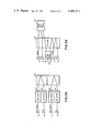
- FIG. 3A is a block diagram depicting the two custom callers without their custom calling features active.
- FIG. 3B is a block diagram depicting the multiple custom calling network arrangement in accordance with the present invention.
- FIG. 1 is a block diagram showing a T-S-T network of a digital switching center for switching a local to local telephone call between POTS subscribers.
- Subscriber A is connected via an analog facility interface unit (FIU) 101.
- the analog FIU 101 has a PCM voice connection to time switch and control unit (TCU) 0.
- TCU time switch and control unit
- Each TCU has 2 time stages associated with it, an originating time stage (OTS) and a terminating time stage (TTS).
- a connection is made from the OTS of a particular TCU to the 64 by 64 space switch 301. Then, a connection is established between the space switch 301 and the terminating time stage of TCU 63, for example. Subscriber B is connected through analog FIU 201 to the TTS of TCU 63.
- a voice transmission link is established from subscriber B to subscriber A.
- This communication link is established via FIU 201, the OTS of TCU 63, through space switch 301, through the TTS of TCU 0, through analog FIU 101 to subscriber A.
- FIU 201 the OTS of TCU 63
- space switch 301 the TTS of TCU 0
- analog FIU 101 to subscriber A.
- FIG. 2 shows the connection of a particular TCU to a corresponding microprocessor CPU 109.
- Each stage of a time and control unit includes an information memory and a control memory.
- the originating time stage OTS shown includes an information memory 309 and a control memory 409.
- Microprocessor interface 209 connects the CPU 109 to the control memories 409 and 509.
- the information memories 309 and 609 each contain information memory units with PCM samples. Up to four FIU's may be connected to each TCU. These FIU's may be analog line FIU's, connecting telephone subscribers to the network, as shown in FIG. 1 or analog trunk FIU's for connecting calls to service or outgoing trunk circuits.
- network 10 includes such elements as analog FIU's, time switch and control units, which further include information and control memories, and a space switching stage.
- Subscriber A who is a three way calling subscriber, is shown connected through network 20 to subscriber B, a POTS subscriber.
- Subscriber C a call waiting subscriber
- subscriber D a POTS subscriber
- Both calls (call one between subscribers A and B and call two between subscribers C and D) are connected via the same switching center. These calls are not in custom calling service at this time.
- the program of the CPU detects the request for a three way call.
- the called subscriber C is examined to determine the custom calling status of this subscriber. Since subscriber C is a call waiting subscriber and calling subscriber A is a three way calling subscriber, there is a multiple custom calling situation and special handling must occur.
- the program then connects three way call trunk 30 while momentarily holding subscribers A and B.
- the CPU's stored program selects an alternate route through switching network 20 to loop around trunk 10, instead of selecting a path through switching network 20 to subscriber C directly.
- the outpulsing of subscriber C's digits takes place analogous to a conventional incoming trunk. That is, the loop around trunk 10 appears as an incoming trunk while performing the outpulsing operation.
- the loop around trunk makes the two custom calls appear as though they are in different switching centers connected by a trunk circuit. As a result, the control trunk logic is minimized.
- the program logic required for outgoing custom calls and intra-office custom calls may be similar resulting in the great savings of program logic.
- the program logic saved via loop around this configuration is equivalent to approximately 1000 manhours of design development time.
Abstract
Description
Claims (4)
Priority Applications (5)
| Application Number | Priority Date | Filing Date | Title |
|---|---|---|---|
| US06/316,252 US4445211A (en) | 1981-10-29 | 1981-10-29 | Arrangement for multiple custom calling |
| CA000413601A CA1186038A (en) | 1981-10-29 | 1982-10-18 | Arrangement for multiple custom calling |
| IT23976/82A IT1155411B (en) | 1981-10-29 | 1982-10-28 | ARRANGEMENT FOR MULTIPLE SPECIAL TELEPHONE CALLS |
| JP57188271A JPS5883460A (en) | 1981-10-29 | 1982-10-28 | Device for plural custom call |
| BE2/59887A BE894838A (en) | 1981-10-29 | 1982-10-28 | SYSTEM ALLOWING MULTIPLE TELEPHONE CALLS ON REQUEST |
Applications Claiming Priority (1)
| Application Number | Priority Date | Filing Date | Title |
|---|---|---|---|
| US06/316,252 US4445211A (en) | 1981-10-29 | 1981-10-29 | Arrangement for multiple custom calling |
Publications (1)
| Publication Number | Publication Date |
|---|---|
| US4445211A true US4445211A (en) | 1984-04-24 |
Family
ID=23228239
Family Applications (1)
| Application Number | Title | Priority Date | Filing Date |
|---|---|---|---|
| US06/316,252 Expired - Fee Related US4445211A (en) | 1981-10-29 | 1981-10-29 | Arrangement for multiple custom calling |
Country Status (5)
| Country | Link |
|---|---|
| US (1) | US4445211A (en) |
| JP (1) | JPS5883460A (en) |
| BE (1) | BE894838A (en) |
| CA (1) | CA1186038A (en) |
| IT (1) | IT1155411B (en) |
Cited By (25)
| Publication number | Priority date | Publication date | Assignee | Title |
|---|---|---|---|---|
| EP0218862A1 (en) * | 1985-09-27 | 1987-04-22 | Siemens Aktiengesellschaft | Method for connecting additional telephone paths and sound signals at an existing telephone connexion between two subscribers |
| US4974097A (en) * | 1986-11-18 | 1990-11-27 | Canon Kabushiki Kaisha | Data communication apparatus |
| US5086424A (en) * | 1989-02-09 | 1992-02-04 | Fujitsu Limited | Communication terminal connection system |
| US5319702A (en) * | 1992-07-29 | 1994-06-07 | Tele-Matic Corporation | Method and apparatus for detecting and responding to hook flash events occurring on a remote telephone |
| US5426706A (en) * | 1991-03-28 | 1995-06-20 | Wood; William H. | Remote simultaneous interpretation system |
| US5619561A (en) * | 1995-06-22 | 1997-04-08 | Reese; Morris | Call-waiting and caller identification with three-way conversations arrangements |
| US5796811A (en) * | 1995-11-15 | 1998-08-18 | Gateway Technologies, Inc. | Three way call detection |
| US5805685A (en) * | 1995-11-15 | 1998-09-08 | Gateway Technologies, Inc. | Three way call detection by counting signal characteristics |
| US20040014462A1 (en) * | 2002-07-12 | 2004-01-22 | Surette Craig Michael | System and method for offering portable language interpretation services |
| US20070064915A1 (en) * | 2005-09-13 | 2007-03-22 | Moore James L Jr | Language interpretation call transferring in a telecommunications network |
| US20070064916A1 (en) * | 2005-09-13 | 2007-03-22 | Language Line Services, Inc. | System and Method for Providing a Language Access Line |
| US20070121903A1 (en) * | 2005-09-13 | 2007-05-31 | Language Line Services, Inc. | Systems and methods for providing a language interpretation line |
| US20070239625A1 (en) * | 2006-04-05 | 2007-10-11 | Language Line Services, Inc. | System and method for providing access to language interpretation |
| US20070242658A1 (en) * | 2006-04-13 | 2007-10-18 | Evercom Systems, Inc. | Unauthorized call activity detection and prevention systems and methods for a voice over internet protocol environment |
| US20070263810A1 (en) * | 2006-04-24 | 2007-11-15 | Language Line Services, Inc. | System and method for providing incoming call distribution |
| US20080086681A1 (en) * | 2006-09-22 | 2008-04-10 | Language Line Services, Inc. | Systems and methods for providing relayed language interpretation |
| US7505406B1 (en) | 2001-07-13 | 2009-03-17 | Evercom Systems, Inc. | Public telephone control with voice over internet protocol transmission |
| US20090090282A1 (en) * | 2007-10-09 | 2009-04-09 | Harris Gold | Waste energy conversion system |
| US7529357B1 (en) | 2003-08-15 | 2009-05-05 | Evercom Systems, Inc. | Inmate management and call processing systems and methods |
| US7899167B1 (en) | 2003-08-15 | 2011-03-01 | Securus Technologies, Inc. | Centralized call processing |
| US8000269B1 (en) | 2001-07-13 | 2011-08-16 | Securus Technologies, Inc. | Call processing with voice over internet protocol transmission |
| US9560193B1 (en) | 2002-04-29 | 2017-01-31 | Securus Technologies, Inc. | Systems and methods for detecting a call anomaly using biometric identification |
| US9990683B2 (en) | 2002-04-29 | 2018-06-05 | Securus Technologies, Inc. | Systems and methods for acquiring, accessing, and analyzing investigative information |
| US10115080B2 (en) | 2002-04-29 | 2018-10-30 | Securus Technologies, Inc. | System and method for proactively establishing a third-party payment account for services rendered to a resident of a controlled-environment facility |
| US10796392B1 (en) | 2007-05-22 | 2020-10-06 | Securus Technologies, Llc | Systems and methods for facilitating booking, bonding and release |
Citations (6)
| Publication number | Priority date | Publication date | Assignee | Title |
|---|---|---|---|---|
| US3504123A (en) * | 1964-01-28 | 1970-03-31 | Siemens Ag | Time multiplex exchange system to permit stations participating in existing connections to establish a further connection |
| US3517135A (en) * | 1962-09-04 | 1970-06-23 | Siemens Ag | Time multiplex communication system employing third party break-in apparatus including speech energy stores |
| US3967070A (en) * | 1975-08-21 | 1976-06-29 | Gte Automatic Electric Laboratories Incorporated | Memory operation for 3-way communications |
| US3997731A (en) * | 1975-04-14 | 1976-12-14 | International Telephone And Telegraph Corporation | Apparatus for custom calling features in a telephone system |
| JPS5220712A (en) * | 1975-08-11 | 1977-02-16 | Meisei Electric Co Ltd | Call waiting system |
| JPS5656063A (en) * | 1979-10-12 | 1981-05-16 | Oki Electric Ind Co Ltd | Call waiting system in digital telephone switch-board |
-
1981
- 1981-10-29 US US06/316,252 patent/US4445211A/en not_active Expired - Fee Related
-
1982
- 1982-10-18 CA CA000413601A patent/CA1186038A/en not_active Expired
- 1982-10-28 BE BE2/59887A patent/BE894838A/en not_active IP Right Cessation
- 1982-10-28 IT IT23976/82A patent/IT1155411B/en active
- 1982-10-28 JP JP57188271A patent/JPS5883460A/en active Pending
Patent Citations (6)
| Publication number | Priority date | Publication date | Assignee | Title |
|---|---|---|---|---|
| US3517135A (en) * | 1962-09-04 | 1970-06-23 | Siemens Ag | Time multiplex communication system employing third party break-in apparatus including speech energy stores |
| US3504123A (en) * | 1964-01-28 | 1970-03-31 | Siemens Ag | Time multiplex exchange system to permit stations participating in existing connections to establish a further connection |
| US3997731A (en) * | 1975-04-14 | 1976-12-14 | International Telephone And Telegraph Corporation | Apparatus for custom calling features in a telephone system |
| JPS5220712A (en) * | 1975-08-11 | 1977-02-16 | Meisei Electric Co Ltd | Call waiting system |
| US3967070A (en) * | 1975-08-21 | 1976-06-29 | Gte Automatic Electric Laboratories Incorporated | Memory operation for 3-way communications |
| JPS5656063A (en) * | 1979-10-12 | 1981-05-16 | Oki Electric Ind Co Ltd | Call waiting system in digital telephone switch-board |
Non-Patent Citations (2)
| Title |
|---|
| "ITT 1240 Digital Exchange", by J. M. Cotton, Electrical Communication, vol. 54, No. 3, 1979, pp. 215-224. |
| ITT 1240 Digital Exchange , by J. M. Cotton, Electrical Communication, vol. 54, No. 3, 1979, pp. 215 224. * |
Cited By (37)
| Publication number | Priority date | Publication date | Assignee | Title |
|---|---|---|---|---|
| EP0218862A1 (en) * | 1985-09-27 | 1987-04-22 | Siemens Aktiengesellschaft | Method for connecting additional telephone paths and sound signals at an existing telephone connexion between two subscribers |
| US4974097A (en) * | 1986-11-18 | 1990-11-27 | Canon Kabushiki Kaisha | Data communication apparatus |
| US5086424A (en) * | 1989-02-09 | 1992-02-04 | Fujitsu Limited | Communication terminal connection system |
| US5426706A (en) * | 1991-03-28 | 1995-06-20 | Wood; William H. | Remote simultaneous interpretation system |
| US5319702A (en) * | 1992-07-29 | 1994-06-07 | Tele-Matic Corporation | Method and apparatus for detecting and responding to hook flash events occurring on a remote telephone |
| US5619561A (en) * | 1995-06-22 | 1997-04-08 | Reese; Morris | Call-waiting and caller identification with three-way conversations arrangements |
| US5796811A (en) * | 1995-11-15 | 1998-08-18 | Gateway Technologies, Inc. | Three way call detection |
| US5805685A (en) * | 1995-11-15 | 1998-09-08 | Gateway Technologies, Inc. | Three way call detection by counting signal characteristics |
| US7505406B1 (en) | 2001-07-13 | 2009-03-17 | Evercom Systems, Inc. | Public telephone control with voice over internet protocol transmission |
| US8000269B1 (en) | 2001-07-13 | 2011-08-16 | Securus Technologies, Inc. | Call processing with voice over internet protocol transmission |
| US10115080B2 (en) | 2002-04-29 | 2018-10-30 | Securus Technologies, Inc. | System and method for proactively establishing a third-party payment account for services rendered to a resident of a controlled-environment facility |
| US10178224B2 (en) | 2002-04-29 | 2019-01-08 | Securus Technologies, Inc. | Systems and methods for detecting a call anomaly using biometric identification |
| US9990683B2 (en) | 2002-04-29 | 2018-06-05 | Securus Technologies, Inc. | Systems and methods for acquiring, accessing, and analyzing investigative information |
| US9560193B1 (en) | 2002-04-29 | 2017-01-31 | Securus Technologies, Inc. | Systems and methods for detecting a call anomaly using biometric identification |
| US20040014462A1 (en) * | 2002-07-12 | 2004-01-22 | Surette Craig Michael | System and method for offering portable language interpretation services |
| US7376415B2 (en) | 2002-07-12 | 2008-05-20 | Language Line Services, Inc. | System and method for offering portable language interpretation services |
| US8340260B1 (en) | 2003-08-15 | 2012-12-25 | Securus Technologies, Inc. | Inmate management and call processing systems and methods |
| US7899167B1 (en) | 2003-08-15 | 2011-03-01 | Securus Technologies, Inc. | Centralized call processing |
| US7529357B1 (en) | 2003-08-15 | 2009-05-05 | Evercom Systems, Inc. | Inmate management and call processing systems and methods |
| US10740861B1 (en) | 2003-11-24 | 2020-08-11 | Securus Technologies, Inc. | Systems and methods for acquiring, accessing, and analyzing investigative information |
| US20070064915A1 (en) * | 2005-09-13 | 2007-03-22 | Moore James L Jr | Language interpretation call transferring in a telecommunications network |
| US8023626B2 (en) | 2005-09-13 | 2011-09-20 | Language Line Services, Inc. | System and method for providing language interpretation |
| US20070064916A1 (en) * | 2005-09-13 | 2007-03-22 | Language Line Services, Inc. | System and Method for Providing a Language Access Line |
| WO2007032783A1 (en) * | 2005-09-13 | 2007-03-22 | Language Line Services, Inc. | Language interpretation call transferring in a telecommunications network |
| US7792276B2 (en) | 2005-09-13 | 2010-09-07 | Language Line Services, Inc. | Language interpretation call transferring in a telecommunications network |
| US7894596B2 (en) | 2005-09-13 | 2011-02-22 | Language Line Services, Inc. | Systems and methods for providing language interpretation |
| WO2007032782A1 (en) * | 2005-09-13 | 2007-03-22 | Language Line Services, Inc. | System and method for providing a language access line |
| US20070121903A1 (en) * | 2005-09-13 | 2007-05-31 | Language Line Services, Inc. | Systems and methods for providing a language interpretation line |
| US20070239625A1 (en) * | 2006-04-05 | 2007-10-11 | Language Line Services, Inc. | System and method for providing access to language interpretation |
| US20070242658A1 (en) * | 2006-04-13 | 2007-10-18 | Evercom Systems, Inc. | Unauthorized call activity detection and prevention systems and methods for a voice over internet protocol environment |
| US7916845B2 (en) | 2006-04-13 | 2011-03-29 | Securus Technologies, Inc. | Unauthorized call activity detection and prevention systems and methods for a Voice over Internet Protocol environment |
| US20070263810A1 (en) * | 2006-04-24 | 2007-11-15 | Language Line Services, Inc. | System and method for providing incoming call distribution |
| US7593523B2 (en) | 2006-04-24 | 2009-09-22 | Language Line Services, Inc. | System and method for providing incoming call distribution |
| US20080086681A1 (en) * | 2006-09-22 | 2008-04-10 | Language Line Services, Inc. | Systems and methods for providing relayed language interpretation |
| US7773738B2 (en) | 2006-09-22 | 2010-08-10 | Language Line Services, Inc. | Systems and methods for providing relayed language interpretation |
| US10796392B1 (en) | 2007-05-22 | 2020-10-06 | Securus Technologies, Llc | Systems and methods for facilitating booking, bonding and release |
| US20090090282A1 (en) * | 2007-10-09 | 2009-04-09 | Harris Gold | Waste energy conversion system |
Also Published As
| Publication number | Publication date |
|---|---|
| IT8223976A0 (en) | 1982-10-28 |
| CA1186038A (en) | 1985-04-23 |
| BE894838A (en) | 1983-02-14 |
| IT1155411B (en) | 1987-01-28 |
| JPS5883460A (en) | 1983-05-19 |
Similar Documents
| Publication | Publication Date | Title |
|---|---|---|
| US4445211A (en) | Arrangement for multiple custom calling | |
| US5513251A (en) | Method for providing call waiting service | |
| US5862208A (en) | Method and system for enabling a party to change terminals during a call | |
| US5583929A (en) | Customer oriented telecommunications network | |
| US5428608A (en) | Call connection technique | |
| US5850434A (en) | Telecommunications network | |
| EP0641112B1 (en) | Telephone routing system with queuing and voice messaging capabilities | |
| EP0579287B1 (en) | Interface to and operation of a voice messaging system | |
| US5668853A (en) | Telecommunications calling feature method and apparatus | |
| EP0836336B1 (en) | Coverage of redirected calls | |
| SE516737C2 (en) | Call Connection Procedure | |
| US7489769B2 (en) | Method and system for providing a continuous tone source using a network node | |
| US4446553A (en) | Arrangement for multiple custom calling | |
| EP0893928A2 (en) | Mediation of traffic in an advanced intelligent network | |
| US4446554A (en) | Arrangement for multiple custom calling | |
| US5644632A (en) | Distributed key telephone station network | |
| EP1269769B1 (en) | Computer telephony integration | |
| US4445212A (en) | Arrangement for multiple custom calling | |
| CA1190633A (en) | Arrangement for multiple custom calling | |
| US5608790A (en) | Trunk utilization in a telecommunications network | |
| EP0748133B1 (en) | Method for operating a telecommunications network and associated network | |
| US7551733B2 (en) | Methods and devices for establishing an area party line service for telephone calls | |
| KR20010106506A (en) | Enhanced Call Waiting | |
| JPS6387064A (en) | Exclusive line camp-on system | |
| AU1754600A (en) | Process for handling a conference call |
Legal Events
| Date | Code | Title | Description |
|---|---|---|---|
| AS | Assignment |
Owner name: GTE AUTOMATIC ELECTRIC LABORATORIES INCORPORATED N Free format text: ASSIGNMENT OF ASSIGNORS INTEREST.;ASSIGNOR:WEBBER, ROBERT C.;REEL/FRAME:003949/0909 Effective date: 19811019 Owner name: GTE AUTOMATIC ELECTRIC LABORATORIES INCORPORATED, Free format text: ASSIGNMENT OF ASSIGNORS INTEREST;ASSIGNOR:WEBBER, ROBERT C.;REEL/FRAME:003949/0909 Effective date: 19811019 |
|
| AS | Assignment |
Owner name: GTE AUTOMATIC ELECTRIC INCORPORATED, A CORP. OF DE Free format text: ASSIGNMENT OF ASSIGNORS INTEREST.;ASSIGNOR:GTE AUTOMATIC ELECTRIC LABORATORIES INCORPORATED;REEL/FRAME:004081/0217 Effective date: 19820524 |
|
| FPAY | Fee payment |
Year of fee payment: 4 |
|
| FEPP | Fee payment procedure |
Free format text: PAYOR NUMBER ASSIGNED (ORIGINAL EVENT CODE: ASPN); ENTITY STATUS OF PATENT OWNER: LARGE ENTITY |
|
| FPAY | Fee payment |
Year of fee payment: 8 |
|
| FEPP | Fee payment procedure |
Free format text: PAYOR NUMBER ASSIGNED (ORIGINAL EVENT CODE: ASPN); ENTITY STATUS OF PATENT OWNER: LARGE ENTITY Free format text: PAYER NUMBER DE-ASSIGNED (ORIGINAL EVENT CODE: RMPN); ENTITY STATUS OF PATENT OWNER: LARGE ENTITY |
|
| REMI | Maintenance fee reminder mailed | ||
| LAPS | Lapse for failure to pay maintenance fees | ||
| FP | Lapsed due to failure to pay maintenance fee |
Effective date: 19960424 |
|
| STCH | Information on status: patent discontinuation |
Free format text: PATENT EXPIRED DUE TO NONPAYMENT OF MAINTENANCE FEES UNDER 37 CFR 1.362 |