US4440153A - Solar concentrator - Google Patents
Solar concentrator Download PDFInfo
- Publication number
- US4440153A US4440153A US06/353,387 US35338782A US4440153A US 4440153 A US4440153 A US 4440153A US 35338782 A US35338782 A US 35338782A US 4440153 A US4440153 A US 4440153A
- Authority
- US
- United States
- Prior art keywords
- block
- absorber
- solar concentrator
- solar
- incident surface
- Prior art date
- Legal status (The legal status is an assumption and is not a legal conclusion. Google has not performed a legal analysis and makes no representation as to the accuracy of the status listed.)
- Expired - Fee Related
Links
Images
Classifications
-
- F—MECHANICAL ENGINEERING; LIGHTING; HEATING; WEAPONS; BLASTING
- F24—HEATING; RANGES; VENTILATING
- F24S—SOLAR HEAT COLLECTORS; SOLAR HEAT SYSTEMS
- F24S23/00—Arrangements for concentrating solar-rays for solar heat collectors
- F24S23/70—Arrangements for concentrating solar-rays for solar heat collectors with reflectors
- F24S23/74—Arrangements for concentrating solar-rays for solar heat collectors with reflectors with trough-shaped or cylindro-parabolic reflective surfaces
-
- F—MECHANICAL ENGINEERING; LIGHTING; HEATING; WEAPONS; BLASTING
- F24—HEATING; RANGES; VENTILATING
- F24S—SOLAR HEAT COLLECTORS; SOLAR HEAT SYSTEMS
- F24S23/00—Arrangements for concentrating solar-rays for solar heat collectors
-
- Y—GENERAL TAGGING OF NEW TECHNOLOGICAL DEVELOPMENTS; GENERAL TAGGING OF CROSS-SECTIONAL TECHNOLOGIES SPANNING OVER SEVERAL SECTIONS OF THE IPC; TECHNICAL SUBJECTS COVERED BY FORMER USPC CROSS-REFERENCE ART COLLECTIONS [XRACs] AND DIGESTS
- Y02—TECHNOLOGIES OR APPLICATIONS FOR MITIGATION OR ADAPTATION AGAINST CLIMATE CHANGE
- Y02E—REDUCTION OF GREENHOUSE GAS [GHG] EMISSIONS, RELATED TO ENERGY GENERATION, TRANSMISSION OR DISTRIBUTION
- Y02E10/00—Energy generation through renewable energy sources
- Y02E10/40—Solar thermal energy, e.g. solar towers
- Y02E10/44—Heat exchange systems
Definitions
- the invention relates to a solar concentrator having a concave mirror which concentrates the sun's rays on an absorber surface arranged between the mirror and the sun.
- the mirror is formed of a solid block of transparent material the lower side of which has a convex shape and is provided with a reflecting coating and that in or on the upper side of the block there is provided the absorber surface.
- the solar concentrator is a compact unit whose parts cannot be moved with respect to each other thereby ensuring that the optimum distance and the exact adjustment is constantly maintained.
- the concentrator can also be easily arranged side by side with other similar concentrators so that large areas can be formed without creating large unused intermediate spaces.
- An optimum concentration of the sun's rays is achieved in that the lower side in at least one section is parabolically shaped. If a concentration is to be achieved not only along a line, but also in a dotted pattern, the lower side must be paraboloidally shaped.
- An enlargement of the focal point to the size of the absorber surface used is achieved in that the lower side is parabolically or approximately parabolically shaped in section in the central region and the outer regions are curved to such an extent that the focal point is enlarged or extended.
- the upper surface of the block is arranged at right angles to the main direction of the sun's rays.
- the upper side of the block is level with and at right angles to the parabola axis.
- At least one cross section of the block is a parabola segment.
- An enlargement of the focal point is achieved in that the parabola segment at least in the two outer regions is slightly less curved than the exact shape of the parabola.
- a high optical quality is achieved in that the reverse side is provided with a mirror like coating, especially of vapor deposited silver.
- the upper side be coated with a scratch-proof, thin transparent material.
- the absorber surface is a solar cell (semiconductor photo element) or a balcked heat conductor element.
- An enlarged absorber surface and/or a smooth upper side is achieved in that the solar cell or the heat conductor element is embedded either partly or completely to the upper side of the block.
- the arrangement of the solar concentrators side by side in a row without residual spaces is achieved by forming the peripheral areas of the flat upper side and thus the side edges of the block into a rectangle, square, five or six sided shape. This has the additional advantage of reducing the less efficient areas of the mirrors.
- the solar concentrator achieves a particularly high degree of efficiency when the approximately parabolically shaped mirror surface deviates from the shape of the parabola to such an extent that at a lesser distance from the focal point with respect to the mirror surface the rays in cross section form the surface shape especially of the rectangular absorber surface, and that the absorber surface is arranged inside this distance.
- the flat upper surface is approximately rectangular in shape and lateral surfaces of the block, which are formed of parabolic segments, border on at right angles to the two longitudinal edges. This enables a plurality of blocks to be arranged side by side with the lateral surfaces contacting each other.
- a duct for securing of the blocks with respect to each other there is provided in or on the upper surface a duct, especially a duct which has a rectangular cross section, for transferring the heat, which is secured to the upper side of the absorber surfaces or the outer wall of which forms the absorber surfaces.
- a heat conducting profile which is secured to the absorber surfaces and which holds the duct.
- a particularly advantageous embodiment which makes special use of the compact construction is provided in that the side of the mirror facing the sun is covered by transparent material at a distance from the mirror or covers the mirror directly without leaving a space. This prevents not only heat losses on the absorber surface but also ensures in a simple manner that the mirror remains completely free of dirt, thereby requiring no regular cleaning and servicing of the mirror. This also protects the mirror from becoming damaged.
- the transparent material can completely fill the hollow mirror, thus further simplifying the manufacturing process and further reducing the danger of damage.
- the transparent material may be glass or a synthetic material and especially an acrylic sheet.
- the absorber surface or the solar cell can be arranged on or in the upper side of the transparent material, this providing additional support and simplifying manufacture and fitting. Especially the absorber surface can be incorporated in the upper side of the transparent material.
- a second transparent material having a refractive index which is such that the sun's rays are refracted with respect to the absorber surface.
- the height of the concentrator can thus be further reduced and radiation striking at a very low angle can still reach the absorber surface.
- the second transparent material may thus be an adhesive agent for the absorber surface, especially a binding substance, so that this material performs a dual function.
- a method for a simple and inexpensive manufacture of high precision, especially mass production, is achieved in that the strength (thickness) of the material is greater than the depth of the concave mirror.
- the fresnel-shaped reverse side of the moulded article is provided with a reflective coating.
- the reverse side after being provided with a reflective coating is provided with a protective layer, especially a layer of lacquer.
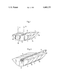
- FIG. 1 an isometric view of two blocks with parabolic lower sides
- FIG. 2 is an isometric view of blocks having partly cylindrical lower sides.
- the solar concentrator comprises a block 15 of a transparent material such as a glass or a clear plastic, especially an acrylic, and has a convex lower side 2 and a flat, level upper side 3.
- the approximately rectangular upper side 3 in operation is at right angles to the main direction of the sun's rays so that the rays are reflected from the upper surface as little as possible.
- the upper side 3 is provided with a thin scratch-proof coating,
- the lower side is of parabolic shape at least with respect to a section which is at right angles to the upper side 3. Furthermore, the lower side 2 may be doubly curved so as to form a part of the paraboloid.
- the block may be formed of a segment or the dome of a paraboloid or it may be made from a slice of a paraboloid dome (segment) the parallel side surfaces of which are arranged parallel to the paraboloid axis and have the same distance from this axis.
- the surface of the upper side 3 is arranged at right angles to the paraboloid axis 16. Since the thickness of the slice is considerably less than the length of the upper side 3, these sliced segments can be placed side by side in a row so that the side surfaces 17 of the blocks 15 contact and cover each other.
- the lower side 2 has a coating of silver vapor deposited upon it and thus forms a hollow mirror filled with the transparent material of the block and which reflects towards the absorber surface 8 the sun's rays collected within the material of the block.
- the absorber surface is formed by a solar cell (semiconductor photo element) or a blacked-out heat conductor element.
- the absorber surface 8 is arranged in the centre of axis 16 and at right angles to the same, but not precisely in the focal point of the hollow mirror, but opposite the focal point displaced with respect to the mirror in the direction of axis 16 so that the rays do not strike the absorber surface 8 at one point, but within the area.
- the outermost regions 18, which are at a further distance from the axis 16 are provided with a smaller radius of curvature than the exact shape of the parabola so that the surface which is struck by the sun' s rays is extended in the longitudinal direction of the upper side 3 and thus takes on the shape approximately of the quadratic absorber surface 8.
- the shape of the parabola is enlarged to such an extent it may not be necessary to place the absorber surface outside the focal point.
- the block 15 need not necessarily be a disc which is parallel to the paraboloid axis, but may also be a quadratic, regular five sided or regular six sided cut away portion of a paraboloid or an elongated semicylinder, the upper side 3 then being quadratic, five sided or six sided and the side surfaces 17 at right angles contacting the sides of the upper side.
- the paraboloid axis 16 is thereby always situated in the center of the block and at right angles to the upper side. Blocks formed in this manner can be formed into larger surfaces by being placed next to each other without forming unused intermediate spaces.
- FIG. 2 is different from that according to FIG. 1 in that amongst other things a heat conducting U-profile 19 is incorporated in the upper side in such a way that the opening is on the top and the profile is arranged at right angles to the side surfaces 17.
- the outer sides of the U-profile form the absorber surfaces.
- a duct 11 is force fitted into the U-profile and the heat transfer medium is passed through the duct 11.
- the disc-shaped blocks 15 according to FIG. 2 on their lower side are curved not twice, but only once, and therefore in cross section forms part of the parabolic discs. This shape is advantageous when the absorber surface extends over the entire thickness of the discs.
- Acrylic is poured into a round, rectangular or partly cylindrical hollow meld the base of which extends outwards in a parabolic shape so that after removal, the reverse side of the moulded article has a parabolic arc.
- the lower side of the moulded article is provided with a reflective coating so that the sun's rays striking the upper side are reflected within the acrylic glass disc 4.
- the concentrator can have the solar cell arranged in a recess on the upper side 3 of the acrylic body.
- a cup-shaped recess 10, or a groove-like recess is larger than the dimensions of the solar cell, the base and the sides of the recess extending parallel to the surface and the sides of the solar cell.
- the intermediate space between the solar cell and the walls of the recess is filled with an acrylic glass, which has a different index of refraction from the acrylic of the acrylic body, which refracts the rays in the direction towards the absorber surface.
Abstract
Description
Claims (12)
Applications Claiming Priority (2)
| Application Number | Priority Date | Filing Date | Title |
|---|---|---|---|
| DE3107888 | 1981-03-02 | ||
| DE19813107888 DE3107888A1 (en) | 1981-03-02 | 1981-03-02 | SOLAR CONCENTRATOR |
Publications (1)
| Publication Number | Publication Date |
|---|---|
| US4440153A true US4440153A (en) | 1984-04-03 |
Family
ID=6126153
Family Applications (1)
| Application Number | Title | Priority Date | Filing Date |
|---|---|---|---|
| US06/353,387 Expired - Fee Related US4440153A (en) | 1981-03-02 | 1982-03-01 | Solar concentrator |
Country Status (4)
| Country | Link |
|---|---|
| US (1) | US4440153A (en) |
| EP (1) | EP0059464B1 (en) |
| AT (1) | ATE26881T1 (en) |
| DE (2) | DE3107888A1 (en) |
Cited By (39)
| Publication number | Priority date | Publication date | Assignee | Title |
|---|---|---|---|---|
| US4610518A (en) * | 1984-12-14 | 1986-09-09 | Clegg John E | Involute beam concentrator |
| US4663495A (en) * | 1985-06-04 | 1987-05-05 | Atlantic Richfield Company | Transparent photovoltaic module |
| US5288337A (en) * | 1992-06-25 | 1994-02-22 | Siemens Solar Industries, L.P. | Photovoltaic module with specular reflector |
| US6294723B2 (en) * | 1998-02-26 | 2001-09-25 | Hitachi, Ltd. | Photovoltaic device, photovoltaic module and establishing method of photovoltaic system |
| US20050081909A1 (en) * | 2003-10-20 | 2005-04-21 | Paull James B. | Concentrating solar roofing shingle |
| US20060235717A1 (en) * | 2005-04-18 | 2006-10-19 | Solaria Corporation | Method and system for manufacturing solar panels using an integrated solar cell using a plurality of photovoltaic regions |
| US20060283495A1 (en) * | 2005-06-06 | 2006-12-21 | Solaria Corporation | Method and system for integrated solar cell using a plurality of photovoltaic regions |
| US20080178922A1 (en) * | 2005-07-26 | 2008-07-31 | Solaria Corporation | Method and system for manufacturing solar panels using an integrated solar cell using a plurality of photovoltaic regions |
| US20080196759A1 (en) * | 2007-02-16 | 2008-08-21 | Thomas Brezoczky | Photovoltaic assembly with elongated photovoltaic devices and integrated involute-based reflectors |
| US20080236664A1 (en) * | 2007-04-02 | 2008-10-02 | Solaria Corporation | Method and system for assembling a solar cell package |
| US20080236651A1 (en) * | 2007-04-02 | 2008-10-02 | Solaria Corporation | Solar cell concentrator structure including a plurality of concentrator elements with a notch design and method having a predetermined efficiency |
| US20080289689A1 (en) * | 2007-05-21 | 2008-11-27 | Solaria Corporation | Concentrating module and method of manufacture for photovoltaic strips |
| US20090056788A1 (en) * | 2007-09-05 | 2009-03-05 | Solaria Corporation | Notch structure for concentrating module and method of manufacture using photovoltaic strips |
| US20090078303A1 (en) * | 2007-09-24 | 2009-03-26 | Solyndra, Inc. | Encapsulated Photovoltaic Device Used With A Reflector And A Method of Use for the Same |
| US20090120487A1 (en) * | 2005-09-12 | 2009-05-14 | Solaria Corporation | Method and System for Assembling A Solar Cell Using a Plurality of Photovoltaic Regions |
| US20090152745A1 (en) * | 2007-12-12 | 2009-06-18 | Solaria Corporation | Method and system for manufacturing integrated molded concentrator photovoltaic device |
| US20090151770A1 (en) * | 2007-12-12 | 2009-06-18 | Solaria Corporation | Method and material for coupling solar concentrators and photovoltaic devices |
| US20090188563A1 (en) * | 2007-09-05 | 2009-07-30 | Solaria Corporation | Solar Cell Structure Including A Plurality of Concentrator Elements With A Notch Design and Predetermined Radii and Method |
| US20100132795A1 (en) * | 2007-01-30 | 2010-06-03 | Thomas Brezoczky | Photovoltaic apparatus having an elongated photovoltaic device using an involute-based concentrator |
| CN101806495A (en) * | 2009-02-18 | 2010-08-18 | 帕洛阿尔托研究中心公司 | Two parts solar energy collecting system with removable solar collector parts |
| US20100206379A1 (en) * | 2009-02-18 | 2010-08-19 | Palo Alto Research Center Incorporated | Rotational Trough Reflector Array With Solid Optical Element For Solar-Electricity Generation |
| US20100206357A1 (en) * | 2009-02-18 | 2010-08-19 | Palo Alto Research Center Incorporated | Two-Part Solar Energy Collection System With Replaceable Solar Collector Component |
| US20100282316A1 (en) * | 2007-04-02 | 2010-11-11 | Solaria Corporation | Solar Cell Concentrator Structure Including A Plurality of Glass Concentrator Elements With A Notch Design |
| US20110017263A1 (en) * | 2007-09-05 | 2011-01-27 | Solaria Corporation | Method and device for fabricating a solar cell using an interface pattern for a packaged design |
| US7910822B1 (en) | 2005-10-17 | 2011-03-22 | Solaria Corporation | Fabrication process for photovoltaic cell |
| EP2221552A3 (en) * | 2009-02-18 | 2012-07-04 | Palo Alto Research Center Incorporated | Rotational Trough Reflector Array with Solid Optical Element for Solar-Electricity Generation |
| US8227688B1 (en) | 2005-10-17 | 2012-07-24 | Solaria Corporation | Method and resulting structure for assembling photovoltaic regions onto lead frame members for integration on concentrating elements for solar cells |
| US8389851B2 (en) | 2007-02-02 | 2013-03-05 | Palo Alto Research Center Incorporated | Metal trace fabrication for optical element |
| US8513095B1 (en) | 2007-09-04 | 2013-08-20 | Solaria Corporation | Method and system for separating photovoltaic strips |
| USD699176S1 (en) | 2011-06-02 | 2014-02-11 | Solaria Corporation | Fastener for solar modules |
| US8707736B2 (en) | 2007-08-06 | 2014-04-29 | Solaria Corporation | Method and apparatus for manufacturing solar concentrators using glass process |
| US8752380B2 (en) | 2012-05-22 | 2014-06-17 | Palo Alto Research Center Incorporated | Collapsible solar-thermal concentrator for renewable, sustainable expeditionary power generator system |
| US8884156B2 (en) | 2010-11-29 | 2014-11-11 | Palo Alto Research Center Incorporated | Solar energy harvesting device using stimuli-responsive material |
| WO2015156874A3 (en) * | 2014-01-15 | 2015-12-17 | The Regents Of The Univerity Of Michigan | Integration of epitaxial lift-off solar cells with mini-parabolic concentrator arrays via printing method |
| US9656861B2 (en) | 2014-02-13 | 2017-05-23 | Palo Alto Research Center Incorporated | Solar power harvesting system with metamaterial enhanced solar thermophotovoltaic converter (MESTC) |
| US9691920B2 (en) | 2014-02-13 | 2017-06-27 | Palo Alto Research Center Incorporated | Metamaterial enhanced thermophotovoltaic converter |
| US10141465B2 (en) | 2014-04-04 | 2018-11-27 | The Regents Of The University Of Michigan | Epitaxial lift-off processed GaAs thin-film solar cells integrated with non-tracking mini-compound parabolic concentrators |
| US10288323B2 (en) | 2015-12-15 | 2019-05-14 | Palo Alto Research Center Incorporated | Solar receiver with metamaterials-enhanced solar light absorbing structure |
| US10340187B2 (en) | 2015-03-18 | 2019-07-02 | The Regents Of The University Of Michigan | Strain relief epitaxial lift-off via pre-patterned mesas |
Families Citing this family (6)
| Publication number | Priority date | Publication date | Assignee | Title |
|---|---|---|---|---|
| DE19916514B4 (en) * | 1999-04-13 | 2005-12-15 | Dr. Vetter Gesellschaft für Medizinische Datentechnik mbH | Traceable solar panel |
| DE202007002897U1 (en) * | 2007-02-28 | 2008-07-10 | SCHÜCO International KG | Photovoltaic solar module |
| DE102008001640A1 (en) | 2008-05-07 | 2009-11-12 | Peter Dr.-Ing. Draheim | Photovoltaic concentrator for concentrating sunlight for use in e.g. photovoltaic panel, has mirror component allowing incident light to be deflected onto absorbing element that is statically mounted with respect to mirror component |
| EP2294628B1 (en) | 2008-05-07 | 2012-10-03 | Peter Draheim | Device and method for concentrating incident light |
| DE102009055432A1 (en) | 2009-04-19 | 2010-10-28 | Peter Dr.-Ing. Draheim | Concentrating device for use in photovoltaic array or solar panel for concentrating incident light, particularly sunlight, has statically mounted gutter or trough-shaped mirror body |
| DE102009051589B4 (en) * | 2009-11-02 | 2013-06-13 | Tobias Schmidt | Apparatus for collecting light |
Citations (4)
| Publication number | Priority date | Publication date | Assignee | Title |
|---|---|---|---|---|
| US4120565A (en) * | 1977-06-16 | 1978-10-17 | The United States Of America As Represented By The United States Department Of Energy | Prisms with total internal reflection as solar reflectors |
| US4143233A (en) * | 1977-06-06 | 1979-03-06 | Monsanto Research Corporation | Solar energy collector |
| US4235224A (en) * | 1978-09-20 | 1980-11-25 | Bunk Edward R | Solar heat collector block |
| US4326012A (en) * | 1980-09-18 | 1982-04-20 | Charlton Walter T | Solar power building block |
Family Cites Families (9)
| Publication number | Priority date | Publication date | Assignee | Title |
|---|---|---|---|---|
| US3125091A (en) * | 1964-03-17 | Inflatable solar energy collector | ||
| DE113193C (en) * | ||||
| FR2342558A1 (en) * | 1976-02-27 | 1977-09-23 | Radiotechnique Compelec | Solar photovoltaic cell with back to back transducers - has transducers occupying half surface area of reflector |
| DE2708499C3 (en) * | 1977-02-26 | 1980-10-09 | Schmieder Geb. Steffens, Gertrud, 8031 Gilching | Seasonally controlled solar collector |
| DE2726531A1 (en) * | 1977-06-13 | 1978-12-14 | Swarovski & Co | Concentrating solar heat collector - with parabolic structure for reflecting glass strips around absorber tubes |
| AU509473B2 (en) * | 1977-06-20 | 1980-05-15 | J. B Hennessy | Solar heat collector |
| AT352354B (en) * | 1977-06-23 | 1979-09-10 | Stachetsberger Alfred Ing | SOLAR PANEL |
| JPS5482746A (en) * | 1977-12-13 | 1979-07-02 | Kenjiyu Miyama | Solar heat collector |
| FR2446447A1 (en) * | 1978-12-05 | 1980-08-08 | Comp Generale Electricite | Solar panel providing electrical and thermal outputs - has photovoltaic cells mounted on heat collector, carried longitudinally by mirrored reflectors |
-
1981
- 1981-03-02 DE DE19813107888 patent/DE3107888A1/en not_active Ceased
-
1982
- 1982-02-27 EP EP82101536A patent/EP0059464B1/en not_active Expired
- 1982-02-27 DE DE8282101536T patent/DE3276192D1/en not_active Expired
- 1982-02-27 AT AT82101536T patent/ATE26881T1/en not_active IP Right Cessation
- 1982-03-01 US US06/353,387 patent/US4440153A/en not_active Expired - Fee Related
Patent Citations (4)
| Publication number | Priority date | Publication date | Assignee | Title |
|---|---|---|---|---|
| US4143233A (en) * | 1977-06-06 | 1979-03-06 | Monsanto Research Corporation | Solar energy collector |
| US4120565A (en) * | 1977-06-16 | 1978-10-17 | The United States Of America As Represented By The United States Department Of Energy | Prisms with total internal reflection as solar reflectors |
| US4235224A (en) * | 1978-09-20 | 1980-11-25 | Bunk Edward R | Solar heat collector block |
| US4326012A (en) * | 1980-09-18 | 1982-04-20 | Charlton Walter T | Solar power building block |
Cited By (50)
| Publication number | Priority date | Publication date | Assignee | Title |
|---|---|---|---|---|
| US4610518A (en) * | 1984-12-14 | 1986-09-09 | Clegg John E | Involute beam concentrator |
| US4663495A (en) * | 1985-06-04 | 1987-05-05 | Atlantic Richfield Company | Transparent photovoltaic module |
| US5288337A (en) * | 1992-06-25 | 1994-02-22 | Siemens Solar Industries, L.P. | Photovoltaic module with specular reflector |
| US6294723B2 (en) * | 1998-02-26 | 2001-09-25 | Hitachi, Ltd. | Photovoltaic device, photovoltaic module and establishing method of photovoltaic system |
| US20050081909A1 (en) * | 2003-10-20 | 2005-04-21 | Paull James B. | Concentrating solar roofing shingle |
| US20060235717A1 (en) * | 2005-04-18 | 2006-10-19 | Solaria Corporation | Method and system for manufacturing solar panels using an integrated solar cell using a plurality of photovoltaic regions |
| US20060283495A1 (en) * | 2005-06-06 | 2006-12-21 | Solaria Corporation | Method and system for integrated solar cell using a plurality of photovoltaic regions |
| US20070095386A1 (en) * | 2005-06-06 | 2007-05-03 | Solaria Corporation | Method and system for integrated solar cell using a plurality of photovoltaic regions |
| US20080178922A1 (en) * | 2005-07-26 | 2008-07-31 | Solaria Corporation | Method and system for manufacturing solar panels using an integrated solar cell using a plurality of photovoltaic regions |
| US20080235949A1 (en) * | 2005-07-26 | 2008-10-02 | Solaria Corporation | Method and system for manufacturing solar panels using an integrated solar cell using a plurality of photovoltaic regions |
| US20080236650A1 (en) * | 2005-07-26 | 2008-10-02 | Solaria Corporation | Method and system for manufacturing solar panels using an integrated solar cell using a plurality of photovoltaic regions |
| US20080236740A1 (en) * | 2005-07-26 | 2008-10-02 | Solaria Corporation | Method and system for manufacturing solar panels using an integrated solar cell using a plurality of photovoltaic regions |
| US20090120487A1 (en) * | 2005-09-12 | 2009-05-14 | Solaria Corporation | Method and System for Assembling A Solar Cell Using a Plurality of Photovoltaic Regions |
| US20100282317A1 (en) * | 2005-09-12 | 2010-11-11 | Solaria Corporation | Method and system for assembling a solar cell using a plurality of photovoltaic regions |
| US8227688B1 (en) | 2005-10-17 | 2012-07-24 | Solaria Corporation | Method and resulting structure for assembling photovoltaic regions onto lead frame members for integration on concentrating elements for solar cells |
| US7910822B1 (en) | 2005-10-17 | 2011-03-22 | Solaria Corporation | Fabrication process for photovoltaic cell |
| US20100132795A1 (en) * | 2007-01-30 | 2010-06-03 | Thomas Brezoczky | Photovoltaic apparatus having an elongated photovoltaic device using an involute-based concentrator |
| US8389851B2 (en) | 2007-02-02 | 2013-03-05 | Palo Alto Research Center Incorporated | Metal trace fabrication for optical element |
| US8624102B2 (en) | 2007-02-02 | 2014-01-07 | Palo Alto Research Center Incorporated | Metal trace fabrication for optical element |
| US20080196759A1 (en) * | 2007-02-16 | 2008-08-21 | Thomas Brezoczky | Photovoltaic assembly with elongated photovoltaic devices and integrated involute-based reflectors |
| US20080236664A1 (en) * | 2007-04-02 | 2008-10-02 | Solaria Corporation | Method and system for assembling a solar cell package |
| US20080236651A1 (en) * | 2007-04-02 | 2008-10-02 | Solaria Corporation | Solar cell concentrator structure including a plurality of concentrator elements with a notch design and method having a predetermined efficiency |
| US7910392B2 (en) | 2007-04-02 | 2011-03-22 | Solaria Corporation | Method and system for assembling a solar cell package |
| US20100282316A1 (en) * | 2007-04-02 | 2010-11-11 | Solaria Corporation | Solar Cell Concentrator Structure Including A Plurality of Glass Concentrator Elements With A Notch Design |
| US20080289689A1 (en) * | 2007-05-21 | 2008-11-27 | Solaria Corporation | Concentrating module and method of manufacture for photovoltaic strips |
| US8119902B2 (en) | 2007-05-21 | 2012-02-21 | Solaria Corporation | Concentrating module and method of manufacture for photovoltaic strips |
| US8707736B2 (en) | 2007-08-06 | 2014-04-29 | Solaria Corporation | Method and apparatus for manufacturing solar concentrators using glass process |
| US8513095B1 (en) | 2007-09-04 | 2013-08-20 | Solaria Corporation | Method and system for separating photovoltaic strips |
| US20090056788A1 (en) * | 2007-09-05 | 2009-03-05 | Solaria Corporation | Notch structure for concentrating module and method of manufacture using photovoltaic strips |
| US20110017263A1 (en) * | 2007-09-05 | 2011-01-27 | Solaria Corporation | Method and device for fabricating a solar cell using an interface pattern for a packaged design |
| US20090188563A1 (en) * | 2007-09-05 | 2009-07-30 | Solaria Corporation | Solar Cell Structure Including A Plurality of Concentrator Elements With A Notch Design and Predetermined Radii and Method |
| US8049098B2 (en) | 2007-09-05 | 2011-11-01 | Solaria Corporation | Notch structure for concentrating module and method of manufacture using photovoltaic strips |
| US20090078303A1 (en) * | 2007-09-24 | 2009-03-26 | Solyndra, Inc. | Encapsulated Photovoltaic Device Used With A Reflector And A Method of Use for the Same |
| US7910035B2 (en) | 2007-12-12 | 2011-03-22 | Solaria Corporation | Method and system for manufacturing integrated molded concentrator photovoltaic device |
| US20090151770A1 (en) * | 2007-12-12 | 2009-06-18 | Solaria Corporation | Method and material for coupling solar concentrators and photovoltaic devices |
| US20090152745A1 (en) * | 2007-12-12 | 2009-06-18 | Solaria Corporation | Method and system for manufacturing integrated molded concentrator photovoltaic device |
| EP2221552A3 (en) * | 2009-02-18 | 2012-07-04 | Palo Alto Research Center Incorporated | Rotational Trough Reflector Array with Solid Optical Element for Solar-Electricity Generation |
| US20100206357A1 (en) * | 2009-02-18 | 2010-08-19 | Palo Alto Research Center Incorporated | Two-Part Solar Energy Collection System With Replaceable Solar Collector Component |
| US20100206379A1 (en) * | 2009-02-18 | 2010-08-19 | Palo Alto Research Center Incorporated | Rotational Trough Reflector Array With Solid Optical Element For Solar-Electricity Generation |
| CN101806495A (en) * | 2009-02-18 | 2010-08-18 | 帕洛阿尔托研究中心公司 | Two parts solar energy collecting system with removable solar collector parts |
| US8884156B2 (en) | 2010-11-29 | 2014-11-11 | Palo Alto Research Center Incorporated | Solar energy harvesting device using stimuli-responsive material |
| USD699176S1 (en) | 2011-06-02 | 2014-02-11 | Solaria Corporation | Fastener for solar modules |
| US8752380B2 (en) | 2012-05-22 | 2014-06-17 | Palo Alto Research Center Incorporated | Collapsible solar-thermal concentrator for renewable, sustainable expeditionary power generator system |
| WO2015156874A3 (en) * | 2014-01-15 | 2015-12-17 | The Regents Of The Univerity Of Michigan | Integration of epitaxial lift-off solar cells with mini-parabolic concentrator arrays via printing method |
| US10069033B2 (en) | 2014-01-15 | 2018-09-04 | The Regents Of The University Of Michigan | Integration of epitaxial lift-off solar cells with mini-parabolic concentrator arrays via printing method |
| US9656861B2 (en) | 2014-02-13 | 2017-05-23 | Palo Alto Research Center Incorporated | Solar power harvesting system with metamaterial enhanced solar thermophotovoltaic converter (MESTC) |
| US9691920B2 (en) | 2014-02-13 | 2017-06-27 | Palo Alto Research Center Incorporated | Metamaterial enhanced thermophotovoltaic converter |
| US10141465B2 (en) | 2014-04-04 | 2018-11-27 | The Regents Of The University Of Michigan | Epitaxial lift-off processed GaAs thin-film solar cells integrated with non-tracking mini-compound parabolic concentrators |
| US10340187B2 (en) | 2015-03-18 | 2019-07-02 | The Regents Of The University Of Michigan | Strain relief epitaxial lift-off via pre-patterned mesas |
| US10288323B2 (en) | 2015-12-15 | 2019-05-14 | Palo Alto Research Center Incorporated | Solar receiver with metamaterials-enhanced solar light absorbing structure |
Also Published As
| Publication number | Publication date |
|---|---|
| EP0059464A1 (en) | 1982-09-08 |
| DE3107888A1 (en) | 1982-09-16 |
| EP0059464B1 (en) | 1987-04-29 |
| DE3276192D1 (en) | 1987-06-04 |
| ATE26881T1 (en) | 1987-05-15 |
Similar Documents
| Publication | Publication Date | Title |
|---|---|---|
| US4440153A (en) | Solar concentrator | |
| US4120565A (en) | Prisms with total internal reflection as solar reflectors | |
| AU728400B2 (en) | Photovoltaic device, photovoltaic module and establishing method of photovoltaic system | |
| US4143234A (en) | Solar collector using total internal reflectance | |
| US6008449A (en) | Reflective concentrating solar cell assembly | |
| US4848319A (en) | Refracting solar energy concentrator and thin flexible Fresnel lens | |
| US5288337A (en) | Photovoltaic module with specular reflector | |
| US9435934B2 (en) | Optics for solar concentrators | |
| US20060191566A1 (en) | Solar concentrator system using photonic engineered materials | |
| KR20130140690A (en) | Compact optics for concentration and illumination systems | |
| EP1994336A2 (en) | A hybrid primary optical component for optical concentrators | |
| CA1286270C (en) | Refracting solar energy concentrator and thin flexible fresnel lens | |
| US6061181A (en) | Nontracking light converger | |
| EP2010830A1 (en) | Radiation concentrating device | |
| KR101207852B1 (en) | Planar type high concentration photovoltaic power generator module and sun tracker using this module | |
| US4529831A (en) | Nontracking parabolic collector apparatus | |
| JPH0326801B2 (en) | ||
| KR101059759B1 (en) | Prism Hybrid Solar Concentrator | |
| US4419984A (en) | Radiant energy collector | |
| US4133699A (en) | Shaped edge solar cell coverslide | |
| EP0020153B1 (en) | Radiation collector | |
| AU2017422421B2 (en) | Fresnel light-concentrating apparatus and light-concentrating solar system | |
| EP2176890A2 (en) | A sunlight -concentrator device for a photovoltaic -generating system | |
| Jirka et al. | Linear Fresnel Lenses For Solar Technology Made Of Glass | |
| JPS59133503A (en) | Converging body |
Legal Events
| Date | Code | Title | Description |
|---|---|---|---|
| AS | Assignment |
Owner name: IMCHEMIE KUNSTSTOFF GMBH, ADOLF-FLORING-STR. 22. D Free format text: ASSIGNMENT OF ASSIGNORS INTEREST.;ASSIGNOR:MELCHIOR, BERND;REEL/FRAME:003991/0293 Effective date: 19820226 |
|
| AS | Assignment |
Owner name: VOLKSBANK REMSCHEID E.G., TENTER WEG 1-3, D-5630 R Free format text: ASSIGNMENT OF ASSIGNORS INTEREST.;ASSIGNOR:IMSCHEMIE KUNSTSTOFF GMBH;REEL/FRAME:004611/0376 Effective date: 19860917 Owner name: VOLKSBANK REMSCHEID E.G., TENTER WEG 1-3, D-5630 R Free format text: ASSIGNMENT OF ASSIGNORS INTEREST;ASSIGNOR:IMSCHEMIE KUNSTSTOFF GMBH;REEL/FRAME:004611/0376 Effective date: 19860917 |
|
| MAFP | Maintenance fee payment |
Free format text: PAYMENT OF MAINTENANCE FEE, 4TH YEAR, PL 96-517 (ORIGINAL EVENT CODE: M170); ENTITY STATUS OF PATENT OWNER: LARGE ENTITY Year of fee payment: 4 |
|
| FEPP | Fee payment procedure |
Free format text: PAYOR NUMBER ASSIGNED (ORIGINAL EVENT CODE: ASPN); ENTITY STATUS OF PATENT OWNER: LARGE ENTITY |
|
| FEPP | Fee payment procedure |
Free format text: MAINTENANCE FEE REMINDER MAILED (ORIGINAL EVENT CODE: REM.); ENTITY STATUS OF PATENT OWNER: LARGE ENTITY |
|
| LAPS | Lapse for failure to pay maintenance fees | ||
| FP | Lapsed due to failure to pay maintenance fee |
Effective date: 19920405 |
|
| AS | Assignment |
Owner name: BLUENERGY SOLARWIND, INC., NEW MEXICO Free format text: ASSIGNMENT OF ASSIGNORS INTEREST;ASSIGNORS:MELCHIOR, KARL BERND;BLUENERGY AG LIECHTENSTEIN;BLUENERGY FINANCE TRUST;AND OTHERS;REEL/FRAME:028678/0446 Effective date: 20080815 |
|
| STCH | Information on status: patent discontinuation |
Free format text: PATENT EXPIRED DUE TO NONPAYMENT OF MAINTENANCE FEES UNDER 37 CFR 1.362 |