US4439321A - Filter means - Google Patents

Filter means Download PDF

Info

Publication number
US4439321A
US4439321A US06/388,169 US38816982A US4439321A US 4439321 A US4439321 A US 4439321A US 38816982 A US38816982 A US 38816982A US 4439321 A US4439321 A US 4439321A
Authority
US
United States
Prior art keywords
filter
filter means
sheet material
filter element
casing
Prior art date
Legal status (The legal status is an assumption and is not a legal conclusion. Google has not performed a legal analysis and makes no representation as to the accuracy of the status listed.)
Expired - Lifetime
Application number
US06/388,169
Inventor
Yoshihiro Taki
Hajime Akado
Toshiaki Fukuta
Susumu Miyakawa
Current Assignee (The listed assignees may be inaccurate. Google has not performed a legal analysis and makes no representation or warranty as to the accuracy of the list.)
Denso Corp
Original Assignee
NipponDenso Co Ltd
Priority date (The priority date is an assumption and is not a legal conclusion. Google has not performed a legal analysis and makes no representation as to the accuracy of the date listed.)
Filing date
Publication date
Priority claimed from JP56097036A external-priority patent/JPS58208A/en
Priority claimed from JP56097037A external-priority patent/JPS58209A/en
Application filed by NipponDenso Co Ltd filed Critical NipponDenso Co Ltd
Assigned to NIPPONDENSO CO. ,LTD, 1,1-CHOME, SHOWA-CHO, KARIYA-SHI, AICHI-KEN, JAPAN, A CORP. OF JAPAN reassignment NIPPONDENSO CO. ,LTD, 1,1-CHOME, SHOWA-CHO, KARIYA-SHI, AICHI-KEN, JAPAN, A CORP. OF JAPAN ASSIGNMENT OF ASSIGNORS INTEREST. Assignors: AKADO, HAJIME, FUKUTA, TOSHIAKI, MIYAKAWA, SUSUMU, TAKI, YOSHIHIRO
Application granted granted Critical
Publication of US4439321A publication Critical patent/US4439321A/en
Anticipated expiration legal-status Critical
Expired - Lifetime legal-status Critical Current

Links

Images

Classifications

    • BPERFORMING OPERATIONS; TRANSPORTING
    • B01PHYSICAL OR CHEMICAL PROCESSES OR APPARATUS IN GENERAL
    • B01DSEPARATION
    • B01D46/00Filters or filtering processes specially modified for separating dispersed particles from gases or vapours
    • B01D46/52Particle separators, e.g. dust precipitators, using filters embodying folded corrugated or wound sheet material
    • B01D46/521Particle separators, e.g. dust precipitators, using filters embodying folded corrugated or wound sheet material using folded, pleated material
    • BPERFORMING OPERATIONS; TRANSPORTING
    • B01PHYSICAL OR CHEMICAL PROCESSES OR APPARATUS IN GENERAL
    • B01DSEPARATION
    • B01D46/00Filters or filtering processes specially modified for separating dispersed particles from gases or vapours
    • B01D46/0002Casings; Housings; Frame constructions
    • B01D46/0005Mounting of filtering elements within casings, housings or frames
    • BPERFORMING OPERATIONS; TRANSPORTING
    • B01PHYSICAL OR CHEMICAL PROCESSES OR APPARATUS IN GENERAL
    • B01DSEPARATION
    • B01D46/00Filters or filtering processes specially modified for separating dispersed particles from gases or vapours
    • B01D46/10Particle separators, e.g. dust precipitators, using filter plates, sheets or pads having plane surfaces
    • BPERFORMING OPERATIONS; TRANSPORTING
    • B01PHYSICAL OR CHEMICAL PROCESSES OR APPARATUS IN GENERAL
    • B01DSEPARATION
    • B01D2279/00Filters adapted for separating dispersed particles from gases or vapours specially modified for specific uses
    • B01D2279/60Filters adapted for separating dispersed particles from gases or vapours specially modified for specific uses for the intake of internal combustion engines or turbines

Definitions

  • the present invention relates to a filter means for filtrating fluids.
  • FIG. 1 is a perspective view of a conventional filter means
  • FIG. 2 is an enlarged fragmentary perspective view of the filter means shown in FIG. 1;
  • FIG. 3 is an illustration of a sheet material incorporated in a basic filter means in accordance with the invention.
  • FIG. 4 is an illustration of a folded sheet material
  • FIG. 5 is a perspective view of the basic filter means in accordance with the invention.
  • FIG. 6 is an illustration of a sheet material incorporated in a filter means of a first embodiment of the invention shown in FIG. 7;
  • FIG. 7 is a plan view of the filter means of the first embodiment of the invention.
  • FIG. 8 is a sectional view of an air cleaner for automotive engine incorporating the filter means shown in FIG. 7;
  • FIG. 9 is a perspective view of a supporting frame used in the air cleaner shown in FIG. 8;
  • FIG. 10 shows a sheet material incorporated in a filter means of a second embodiment of the invention shown in FIG. 12;
  • FIG. 11 is an illustration of a folded sheet material
  • FIG. 12 is a perspective view of the filter means of the second embodiment
  • FIG. 13 is an illustration of a sheet material incorporated in a filter means of a third embodiment of the invention shown in FIG. 14;
  • FIG. 14 is a perspective view of the filter means of the third embodiment.
  • FIG. 15 is a plan view of a filter means of a fourth embodiment of the invention.
  • FIG. 16 is a plan view of a filter means of a fifth embodiment of the invention.
  • FIG. 17 is an illustration of a sheet material incorporated in a filter means of a sixth embodiment of the invention shown in FIG. 18;
  • FIG. 18 is a plan view of the filter means of the sixth embodiment of the invention.
  • FIG. 19 is a perspective view of a filter means of a seventh embodiment of the invention incorporating the sheet material shown in FIG. 17;
  • FIG. 20 is a fragmentary perspective view of a filter means of an eighth embodiment of the invention incorporating a filter means shown in FIG. 18;
  • FIG. 21 is an illustration of a sheet material incorporated in a filter means shown in FIG. 22;
  • FIG. 22 is a plan view of the filter means of a nineth embodiment of the invention.
  • FIG. 23 is an illustration of a sheet material incorporated in a filter means shown in FIG. 24;
  • FIG. 24 is a plan view of the filter means of a tenth embodiment of the invention.
  • FIG. 25 is a fragmentary perspective view of a filter means of an eleventh embodiment of the invention.
  • FIG. 26 is a sectional view of an air cleaner for automotive engines incorporating the filter means shown in FIG. 25;
  • FIG. 27 is a sectional view of a lubricating oil cleaner incorporating a modofication of the filter means shown in FIG. 25.
  • FIG. 1 shows a well-known vortical shape air filter means generally designated at a reference numeral 1.
  • the filter means 1 is constructed as explained below.
  • a sheet material 2 composed of a planar sheet half 2a and a corrugated sheet half 2b is prepared and is folded back at their boundary.
  • the sheet material 2 is wound round a core 3 such that the corrugated sheet half 2a contacts the outer peripheral surface of the core 3, thereby constituting the filter means 1.
  • the portion of the gap, which is defined between the planar portion 2a and the corrugated portion 2b of thenext layer and exposed to the air to be filtered is filled with an adhesive4 to form a sealed portion.
  • air to be filtered flows along the flow passages defined between the planar portions 2a and the corrugated portions 2b as indicated by arrows in FIG. 2 and is cleaned as it permeates and flows through the walls of the passages.
  • the portion of the sheet material constituting the radially outer portion is required to have a length greater than that of the portion constituting the radially inner portion. This problem is serious particularly when the diameter of the spirally wound filter means becomes large.
  • the corrugated portion 2b which is intended for preventing the adjacent planar portions 2a, 2a of the folded-back sheet material from contacting each other, is collapsed undesirably to decrease the inlet area for the air to be cleaned, resulting in an increased resistance against the flow of air.
  • portion of the gap defined between the planar portion2a and the corrugated portion 2b of the next layer and exposed to the air to be filtered is filled with an adhesive. Therefore, only about a half ofthe whole area of the filter means exposed to the air is utilized for actually receiving the incoming air. Consequently, the resistance against the air to be filtered is increased inconveniently.
  • an object of the invention is to provide a filter means capable of overcoming the above-described drawbacks of the prior art.
  • a filter means formed of a filter element made of a trapezium or a sector-shaped sheet material.
  • a filter means in which a portion of the filter element is made to have a filteringperformance different from that of the remainder portion of the filter element.
  • a filter means in which the filter element is provided with an additional filter element having a different filtering performance.
  • the filter element incorporated in the filter means of the invention is formed of a stretchable trapezium sheet material 5 having ends of different lengths as shown in FIG. 3.
  • a longitudinal axis line of the trapezium sheet material is divided into a plurality of sections of an equal length, and lines B--B', C--C', . . . , J--J' are formed perpendicularly to the longitudinal axis line at respective points of division.
  • the trapezium sheet material is then foldedin the alternating direction along the respective lines so that a folded sheet material 6 having a corrugated cross-section is obtained as shown inFIG. 4.
  • This folded sheet material 6 is then wound in a loop-like form withthe section AA'BB' of the smallest area located at the innermost position and the opposing ends are jointed to each other by a resin 8 to provide a filter element 7 in the form of concentric circles.
  • the filter means of the invention is characterized in that the above-mentioned filter element has the following feature.
  • a trapezium sheet material 9 shown in FIG. 6 has a plurality of equi-spaced folding lines b--b', c--c', . . . , e--e', as the same in the case of the sheet material 5 mentioned above.
  • the portion 9b defined by lines interconnecting the points a, e, e' and a' is made to have a higher filtering performance than the remainder portion 9a of the trapezium sheetmaterial 9 has.
  • This sheet material 9 is folded as explained before to constitute a filter element 10 in the form of concentric circles in which the high filtering performance portion 9b takes the radially inner position while the low filtering performance portion 9a takes the radiallyouter portion as shown in FIG. 7.
  • the opposing ends of the filter element is bonded by a resin 8 also in this case.
  • the term “high filtering performance” is used to mean “high air permeability”.
  • a receiver 11 made of a resin has an elliptic cylinderportion 11a adapted to fit the inner peripheral surface of the filter element 10 and a porous supporting portion 11b having an elliptic form adapted to support the bottom of the filter element 10.
  • the filter element10 is bonded at its inner peripheral surface to the outer peripheral surface of the elliptic cylinder portion 11a of the receiver 11 by an adhesive A.
  • the outer peripheral surface of the filter element 10 is bonded by an adhesive B to the supporting portion 11b of thereceiver 11.
  • the receiver 11 is placed on a supporting frame 13 (shown in FIG. 9) which is made of a resin and has four legs 13a.
  • the supporting frame 13 is fixed to a cover 12 around a central opening 12a of the latter.
  • a gasket 14 is bonded to the outer peripheral surface of the receiver 11 over the entire periphery of the latter. More specifically, the gasket 14 is placed on the flange of the cover 12 and is covered by a cap 15 to define a chamber 21.
  • the cap 15 and the cover 12 are fixed to each other by means of a bolt 16 extending through the cap 15, receiver 11and the supporting frame 13 and a nut 17 cooperating with the bolt 16. Since the gasket 14 is clamped between the flanges of the cap 15 and of the cover 12, it is possible to retain the chamber 12 in a gas-tight manner.
  • a gasket 18 is used to prevent air leaking through the gap betweenthe bolt 16 and the bores through which the bolt 16 extends.
  • the air to be filtered is introduced through an inlet port 19in a direction tangential to the circle of the filter element 10 and is cleaned as it flows through the filter element 10.
  • the cleaned air is thensupplied to an engine through the holes formed in the supporting portion 11b of the receiver 11, the spaces between adjacent legs 13a of the supporting frame 13 and the central opening 12a of the cover 12.
  • the radially inner portion 9b of the filter element 10 has a higher filtering performance than the radially outer portion 9a of the same.
  • the air flows at a higher velocity in the radially inner portion 9b than in the radially outer portion 9a of the filter element, so that the flow of the air is uniformalized over in entirety of the filter element 10 to improve the cleaning efficiency and the durability of the filter means.
  • the filter element is made from atrapezium sheet material. This, however, is not exclusive and the filter element may be formed from a sector-shaped sheet material as will be understood from the following description.
  • FIGS. 10 to 12 there is prepared a sector-shaped sheet material 22 as shown in FIG. 10. Concentric arcs bb', cc', . . . , jj' arescribed on the sector-shaped sheet material 22 at a constant radial pitch around a common point 0 which is the center of the sector shape of the sheet material 22. Then, the sheet material 22 is folded in alternating directions along the arcs bb', cc', . . . , jj' to become a folded sheet material as shown in FIG. 11. Then, the folded sheet material is wound andthe opposing edges thereof are connected to each other by a resin 8 to forma filter element 23 in the form of concentric circles in which, as shown inFIG. 12, the shortest arc aa' constitutes the inner circumference of the filter element 23 while the longest arc kk' constitutes the outer circumference of the filter element 23.
  • the sheet material 22 has such a sector shape that each arc intersects the both edge lines at a right angle. It is, therefore, possible to form the filter element 23 without any difference of the circumferential length. In this case, it is possible to use non-stretchable material such as filter paper, non-woven fabric, felt or the like as the sheet material.
  • the scoring of the arcuate folding lines of the sheet material 22 is made by means of a scoring roller or by a heatprocess.
  • FIGS. 13 and 14 The sector-shaped sheet material 24 shown inFIG. 13 is scored in alternating directions as the same in the case of the sheet material shown in FIG. 10 but in this case the radial pitch of the score lines is changed alternatingly. More specifically, the sections 1-m,n-o, p-q, r-s and t-u have an equal length, while the sections m-n, o-p, q-r, s-t and u-v have an equal length which is greater than the first-mentioned length.
  • This sheet material 24 is folded in the alternating directions along the arcuate lines and the opposing ends are jointed to each other by adhesive 8 thereby to form a filter element 25 asshown in FIG. 14.
  • the line interconnecting the top ridges of the continuous corrugation and the line interconnecting the bottoms of the corrugation extend in parallel with each other and are inclined downwardly with respect to the axis of the filter element 25.
  • FIG. 15 shows a filter element 26 which is formed of a sheet material similar to the sheet material 22 shown in FIG. 10 but having arc lengths which amount to half of that of the sheet material 22.
  • the filter element 26 has a semi-cylindrical form and is sealed at its end surface and inner peripheral surface with a resin 8.
  • the filter element 27 shown in FIG. 16 is composed of a sheet material similar to the sheet material 22 shown in FIG. 10 but the lengths of the arcuate lines amount to 3/4 of those of the sheet material 22.
  • the end surface and the inner peripheral surface of the filter element 27 are sealed by a resin 8.
  • a sheet material 28 shown in FIG. 17 has a substantially sector shape.
  • a group of arcs a 2 a 3 , b 2 b 3 , . . . , j 2 j 3 and k 2 k 3 of different radii centered at the point 0 are scored on the central portion of the sheet material 28.
  • a filter element 30 shown in FIG. 19 is obtained by jointing the opposing ends of the folded sheet material 28 by means of a resin 8.
  • a filter element 31 shown in FIG. 20 having an elliptic cylinder form is produced by preparing a pair of folded sheet materials 28 and jointing the opposing ends of each folded sheet material 28 by means of a resin 8. This filter means is devoid of the core A.
  • a sheet material 32 has a substantially sector shape. Arcs ll', mm' . . . and rr' are scored on the sheet material 32 at an equal radius around different points located on the neutral axis of the sheet material 32. The sheet material 32 is folded in alternating directions along the arcuate lines and the opposing ends are jointed by a resin 8 thereby to form a filter element 33. A core A" is bonded to the inner side of the filter element 33.
  • a sheet material 34 has a substantially sector shape. Arcs 11', mm' . . . , and tt' are scored on the sheet material 34 at different radii around different points located on the neutral axis. The sheet material 34 is folded in the alternating directions along the arcs and the opposing ends are jointed by a resin 8 thereby to form a filter element 35.
  • a filter means 37 is produced by attaching to the inner side of the filter element 7 (shown in FIG. 5) an additional filter element 36 having a filtering performance different from that of the filter element 7, by means of a resin C (shown in FIG. 26).
  • the additional filter element 36 is formed from a material having a higher filtering performance such as urethane foam, but may be formed of a material having a lower filtering performance such as felt, fiber or the like.
  • the filter element 7 is made of a stretchable material such as non-woven fabric as stated before.
  • a reference numeral 111 designates a receiver made of a resin and having an elliptic cylinder portion 111a adapted t fit the inner peripheral surface of the additional filter element 36 and a supporting portion 111b with holes 111c formed integrallywith the cylinder portion so as to support the bottom of the filter means 37 and having an elliptic form.
  • the inner peripheral surface of the additional filter element 36 fits around the cylinder portion 111a of the receiver 111.
  • the outer peripheral surface of the filter means 37 is bonded to the supporting portion 111b of the receiver 111 by means of a bond B.
  • the receiver 111 is placed on a resinous supporting frame 113 and fixed to the portion of a cover 112 adjacent to acentral opening formed in the cover 12.
  • a gasket 114 is bonded to the outerperipheral surface of the receiver 111 over the entire circumference of thelatter.
  • the gasket 114 is placed on the flange of the cover 112 and is covered by a cap 115 to define a chamber 121.
  • the cap 115 and the cover 112 are coupled to each other by means of a bolt 116 extending through thecap 115, receiver 111 and the supporting frame 113, and a nut 117 cooperating with the bolt 116.
  • the chamber 121 is sealed in a gas-tight manner because the gasket 114 is clamped between the flanges of the cap 115 and of the cover 112.
  • a gasket 114 is provided for preventing air leaking through the gap between the bolt 116 and the bores through which the bolt 116 extends.
  • the air to be filtered is introduced through the inlet port 119 in a direction tangential to the circle of the filter means 37 and is cleaned as it passes through the filter means 37.
  • the cleaned air is supplied to the engine through holes 111c formed in thesupporting portion 111b and then through the central opening in the cover 112.
  • a filter 220 shown in FIG. 26
  • a filtering chamber is defined by a tubular case 221and two end walls 222, 233 having central openings and attached to both ends of the tubular case 221.
  • the filter means 39 is fixed to a receiver 224 having holes 224c on the bottom by means of an adhesive B.
  • This receiver 224 is fixed to the inner periphery of the tubular case 221 so as to intersect the axis line of the tubular case 221 at a right angle.
  • the oil to be filtered is introduced into the chamber through the opening in the cap 222 as indicated by arrows and is cleaned as it flows through the filter means 39 before it is discharged through the opening in the cap223.
  • the additional filter element 38 provided at the central portion of the filter means 39 has a filtering performance lower than that of the filter element 7, so that the flow velocity of the lubricating oil in the central portion of the filter means 39 is comparatively low, so that the additional filter element 38 serves as a by-pass. It is thus possible to obtain a by-pass filter.
  • the additional element of the lower filtering performance is provided at the inner portion of the basic filter element, such an arrangement is not exclusive and the additional element of the lower filtering performance may be provided at the outer portion of the basic filter element.
  • the portion of a different filtering performance may be provided at a plurality of points of the filter means.
  • the filter means of the invention offers the following advantages.

Abstract

A filter means for filtering fluid comprises a first filter section and a second filter section. The filter means is formed by using a folded sheet material having a trapezoid or a sector form. The second filter section of the filter means has a filtering performance different from that of the first filter section of the filter means.

Description

BACKGROUND OF THE INVENTION Field of the Invention
The present invention relates to a filter means for filtrating fluids.
BRIEF DESCRIPTION OF THE DRAWINGS
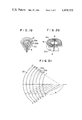
FIG. 1 is a perspective view of a conventional filter means;
FIG. 2 is an enlarged fragmentary perspective view of the filter means shown in FIG. 1;
FIG. 3 is an illustration of a sheet material incorporated in a basic filter means in accordance with the invention;
FIG. 4 is an illustration of a folded sheet material;
FIG. 5 is a perspective view of the basic filter means in accordance with the invention;
FIG. 6 is an illustration of a sheet material incorporated in a filter means of a first embodiment of the invention shown in FIG. 7;
FIG. 7 is a plan view of the filter means of the first embodiment of the invention;
FIG. 8 is a sectional view of an air cleaner for automotive engine incorporating the filter means shown in FIG. 7;
FIG. 9 is a perspective view of a supporting frame used in the air cleaner shown in FIG. 8;
FIG. 10 shows a sheet material incorporated in a filter means of a second embodiment of the invention shown in FIG. 12;
FIG. 11 is an illustration of a folded sheet material;
FIG. 12 is a perspective view of the filter means of the second embodiment;
FIG. 13 is an illustration of a sheet material incorporated in a filter means of a third embodiment of the invention shown in FIG. 14;
FIG. 14 is a perspective view of the filter means of the third embodiment;
FIG. 15 is a plan view of a filter means of a fourth embodiment of the invention;
FIG. 16 is a plan view of a filter means of a fifth embodiment of the invention;
FIG. 17 is an illustration of a sheet material incorporated in a filter means of a sixth embodiment of the invention shown in FIG. 18;
FIG. 18 is a plan view of the filter means of the sixth embodiment of the invention;
FIG. 19 is a perspective view of a filter means of a seventh embodiment of the invention incorporating the sheet material shown in FIG. 17;
FIG. 20 is a fragmentary perspective view of a filter means of an eighth embodiment of the invention incorporating a filter means shown in FIG. 18;
FIG. 21 is an illustration of a sheet material incorporated in a filter means shown in FIG. 22;
FIG. 22 is a plan view of the filter means of a nineth embodiment of the invention;
FIG. 23 is an illustration of a sheet material incorporated in a filter means shown in FIG. 24;
FIG. 24 is a plan view of the filter means of a tenth embodiment of the invention;
FIG. 25 is a fragmentary perspective view of a filter means of an eleventh embodiment of the invention;
FIG. 26 is a sectional view of an air cleaner for automotive engines incorporating the filter means shown in FIG. 25; and
FIG. 27 is a sectional view of a lubricating oil cleaner incorporating a modofication of the filter means shown in FIG. 25.
DESCRIPTION OF THE PRIOR ART
FIG. 1 shows a well-known vortical shape air filter means generally designated at a reference numeral 1. The filter means 1 is constructed as explained below.
A sheet material 2 composed of a planar sheet half 2a and a corrugated sheet half 2b is prepared and is folded back at their boundary. The sheet material 2 is wound round a core 3 such that the corrugated sheet half 2a contacts the outer peripheral surface of the core 3, thereby constituting the filter means 1. As shown in FIG. 2, the portion of the gap, which is defined between the planar portion 2a and the corrugated portion 2b of thenext layer and exposed to the air to be filtered is filled with an adhesive4 to form a sealed portion. In the filter means of the type described, air to be filtered flows along the flow passages defined between the planar portions 2a and the corrugated portions 2b as indicated by arrows in FIG. 2 and is cleaned as it permeates and flows through the walls of the passages.
This known vortical type filter, however, has the following drawbacks.
(1) Since the folded-back sheet material is wound in a spiral form around the core, the portion of the sheet material constituting the radially outer portion is required to have a length greater than that of the portion constituting the radially inner portion. This problem is serious particularly when the diameter of the spirally wound filter means becomes large. In consequence, the corrugated portion 2b, which is intended for preventing the adjacent planar portions 2a, 2a of the folded-back sheet material from contacting each other, is collapsed undesirably to decrease the inlet area for the air to be cleaned, resulting in an increased resistance against the flow of air.
(2) As stated before, portion of the gap defined between the planar portion2a and the corrugated portion 2b of the next layer and exposed to the air to be filtered is filled with an adhesive. Therefore, only about a half ofthe whole area of the filter means exposed to the air is utilized for actually receiving the incoming air. Consequently, the resistance against the air to be filtered is increased inconveniently.
(3) The area taking part in the filtration is decreased due to the adhesivefilling the above-mentioned portion of the gaps. The adhesive is liable to be separated from the portions 2a, 2b of the filter means due to an external force acting on the same so that a gap or gaps are formed betweenthe adhesive 4 and the portion 2a and/or the portion 2b. These gaps inconveniently permit the air to be filtered to pass therethrough without being filtered, so that the cleaning effect is deteriorated seriously.
SUMMARY OF THE INVENTION
Accordingly, an object of the invention is to provide a filter means capable of overcoming the above-described drawbacks of the prior art.
To this end, according to one aspect of the invention, there is provided a filter means formed of a filter element made of a trapezium or a sector-shaped sheet material.
According to another aspect of the invention, there is provided a filter means in which a portion of the filter element is made to have a filteringperformance different from that of the remainder portion of the filter element.
According to still another aspect of the invention, here is provided a filter means in which the filter element is provided with an additional filter element having a different filtering performance.
DESCRIPTION OF THE PREFERRED EMBODIMENTS
Preferred embodiments of the invention will be described hereinunder with reference to the accompanying drawings.
Basically, the filter element incorporated in the filter means of the invention is formed of a stretchable trapezium sheet material 5 having ends of different lengths as shown in FIG. 3.
A longitudinal axis line of the trapezium sheet material is divided into a plurality of sections of an equal length, and lines B--B', C--C', . . . , J--J' are formed perpendicularly to the longitudinal axis line at respective points of division. The trapezium sheet material is then foldedin the alternating direction along the respective lines so that a folded sheet material 6 having a corrugated cross-section is obtained as shown inFIG. 4. This folded sheet material 6 is then wound in a loop-like form withthe section AA'BB' of the smallest area located at the innermost position and the opposing ends are jointed to each other by a resin 8 to provide a filter element 7 in the form of concentric circles.
The filter means of the invention is characterized in that the above-mentioned filter element has the following feature. a trapezium sheet material 9 shown in FIG. 6 has a plurality of equi-spaced folding lines b--b', c--c', . . . , e--e', as the same in the case of the sheet material 5 mentioned above. In addition, the portion 9b defined by lines interconnecting the points a, e, e' and a' is made to have a higher filtering performance than the remainder portion 9a of the trapezium sheetmaterial 9 has. This sheet material 9 is folded as explained before to constitute a filter element 10 in the form of concentric circles in which the high filtering performance portion 9b takes the radially inner position while the low filtering performance portion 9a takes the radiallyouter portion as shown in FIG. 7. The opposing ends of the filter element is bonded by a resin 8 also in this case. Throughout the specification, the term "high filtering performance" is used to mean "high air permeability".
Hereinafter, an explanation will be made to the construction and the operation of an air cleaner 20 for automotive engines incorporating the filter means 10 shown in FIG. 7.
Referring to FIG. 8, a receiver 11 made of a resin has an elliptic cylinderportion 11a adapted to fit the inner peripheral surface of the filter element 10 and a porous supporting portion 11b having an elliptic form adapted to support the bottom of the filter element 10. The filter element10 is bonded at its inner peripheral surface to the outer peripheral surface of the elliptic cylinder portion 11a of the receiver 11 by an adhesive A. On the other hand, the outer peripheral surface of the filter element 10 is bonded by an adhesive B to the supporting portion 11b of thereceiver 11. The receiver 11 is placed on a supporting frame 13 (shown in FIG. 9) which is made of a resin and has four legs 13a. The supporting frame 13 is fixed to a cover 12 around a central opening 12a of the latter. A gasket 14 is bonded to the outer peripheral surface of the receiver 11 over the entire periphery of the latter. More specifically, the gasket 14 is placed on the flange of the cover 12 and is covered by a cap 15 to define a chamber 21. The cap 15 and the cover 12 are fixed to each other by means of a bolt 16 extending through the cap 15, receiver 11and the supporting frame 13 and a nut 17 cooperating with the bolt 16. Since the gasket 14 is clamped between the flanges of the cap 15 and of the cover 12, it is possible to retain the chamber 12 in a gas-tight manner. A gasket 18 is used to prevent air leaking through the gap betweenthe bolt 16 and the bores through which the bolt 16 extends.
In operation, the air to be filtered is introduced through an inlet port 19in a direction tangential to the circle of the filter element 10 and is cleaned as it flows through the filter element 10. The cleaned air is thensupplied to an engine through the holes formed in the supporting portion 11b of the receiver 11, the spaces between adjacent legs 13a of the supporting frame 13 and the central opening 12a of the cover 12. In the described embodiment, the radially inner portion 9b of the filter element 10 has a higher filtering performance than the radially outer portion 9a of the same. In consequence, the air flows at a higher velocity in the radially inner portion 9b than in the radially outer portion 9a of the filter element, so that the flow of the air is uniformalized over in entirety of the filter element 10 to improve the cleaning efficiency and the durability of the filter means.
In the filter means described heretofore, the filter element is made from atrapezium sheet material. This, however, is not exclusive and the filter element may be formed from a sector-shaped sheet material as will be understood from the following description.
Another embodiment of the invention making use of a sector-shaped sheet material will be described hereinunder.
Referring first to FIGS. 10 to 12, there is prepared a sector-shaped sheet material 22 as shown in FIG. 10. Concentric arcs bb', cc', . . . , jj' arescribed on the sector-shaped sheet material 22 at a constant radial pitch around a common point 0 which is the center of the sector shape of the sheet material 22. Then, the sheet material 22 is folded in alternating directions along the arcs bb', cc', . . . , jj' to become a folded sheet material as shown in FIG. 11. Then, the folded sheet material is wound andthe opposing edges thereof are connected to each other by a resin 8 to forma filter element 23 in the form of concentric circles in which, as shown inFIG. 12, the shortest arc aa' constitutes the inner circumference of the filter element 23 while the longest arc kk' constitutes the outer circumference of the filter element 23.
In this filter element 23, the sheet material 22 has such a sector shape that each arc intersects the both edge lines at a right angle. It is, therefore, possible to form the filter element 23 without any difference of the circumferential length. In this case, it is possible to use non-stretchable material such as filter paper, non-woven fabric, felt or the like as the sheet material. The scoring of the arcuate folding lines of the sheet material 22 is made by means of a scoring roller or by a heatprocess.
Still another embodiment of the invention will be made hereinunder with reference to FIGS. 13 and 14. The sector-shaped sheet material 24 shown inFIG. 13 is scored in alternating directions as the same in the case of the sheet material shown in FIG. 10 but in this case the radial pitch of the score lines is changed alternatingly. More specifically, the sections 1-m,n-o, p-q, r-s and t-u have an equal length, while the sections m-n, o-p, q-r, s-t and u-v have an equal length which is greater than the first-mentioned length. This sheet material 24 is folded in the alternating directions along the arcuate lines and the opposing ends are jointed to each other by adhesive 8 thereby to form a filter element 25 asshown in FIG. 14. As will be seen from FIG. 14, the line interconnecting the top ridges of the continuous corrugation and the line interconnecting the bottoms of the corrugation extend in parallel with each other and are inclined downwardly with respect to the axis of the filter element 25.
FIG. 15 shows a filter element 26 which is formed of a sheet material similar to the sheet material 22 shown in FIG. 10 but having arc lengths which amount to half of that of the sheet material 22. The filter element 26 has a semi-cylindrical form and is sealed at its end surface and inner peripheral surface with a resin 8.
The filter element 27 shown in FIG. 16 is composed of a sheet material similar to the sheet material 22 shown in FIG. 10 but the lengths of the arcuate lines amount to 3/4 of those of the sheet material 22. The end surface and the inner peripheral surface of the filter element 27 are sealed by a resin 8.
A further embodiment of the invention will be described hereinunder with reference to FIGS. 17 and 18. A sheet material 28 shown in FIG. 17 has a substantially sector shape. A group of arcs a2 a3, b2 b3, . . . , j2 j3 and k2 k3 of different radii centered at the point 0 are scored on the central portion of the sheet material 28. Also, straight lines a1 -a2, a3 -a4, b1 -b2, b3 -b4, . . . , j1 -j2, j3 -j4, k1 -k2 and k3 -k4 are scored to extend from both ends of respective arcs as illustrated. The scored sheet material 28 is then folded in alternating directions and curved to surround a core A made of an impermeable material such as a resin. The ends of the folded sheet material 28 are sealed with a resin 8 to form a filter element 29. The core A is bonded to the inner side of the filter element 29 by means of an adhesive. A filter element 30 shown in FIG. 19 is obtained by jointing the opposing ends of the folded sheet material 28 by means of a resin 8. A filter element 31 shown in FIG. 20 having an elliptic cylinder form is produced by preparing a pair of folded sheet materials 28 and jointing the opposing ends of each folded sheet material 28 by means of a resin 8. This filter means is devoid of the core A.
A still further embodiment will be described in conjunction with FIGS. 21 and 22. A sheet material 32 has a substantially sector shape. Arcs ll', mm' . . . and rr' are scored on the sheet material 32 at an equal radius around different points located on the neutral axis of the sheet material 32. The sheet material 32 is folded in alternating directions along the arcuate lines and the opposing ends are jointed by a resin 8 thereby to form a filter element 33. A core A" is bonded to the inner side of the filter element 33.
A still further embodiment of the invention will be described with reference to FIGS. 23 and 24. A sheet material 34 has a substantially sector shape. Arcs 11', mm' . . . , and tt' are scored on the sheet material 34 at different radii around different points located on the neutral axis. The sheet material 34 is folded in the alternating directions along the arcs and the opposing ends are jointed by a resin 8 thereby to form a filter element 35.
According to the invention, as shown in FIG. 25, a filter means 37 is produced by attaching to the inner side of the filter element 7 (shown in FIG. 5) an additional filter element 36 having a filtering performance different from that of the filter element 7, by means of a resin C (shown in FIG. 26). The additional filter element 36 is formed from a material having a higher filtering performance such as urethane foam, but may be formed of a material having a lower filtering performance such as felt, fiber or the like. The filter element 7 is made of a stretchable material such as non-woven fabric as stated before.
An explanation will be made hereinunder as to an air cleaner 120 for automotive internal combustion engines incorporating the filter means 37 shown in FIG. 25. Referring to FIG. 26, a reference numeral 111 designatesa receiver made of a resin and having an elliptic cylinder portion 111a adapted t fit the inner peripheral surface of the additional filter element 36 and a supporting portion 111b with holes 111c formed integrallywith the cylinder portion so as to support the bottom of the filter means 37 and having an elliptic form. The inner peripheral surface of the additional filter element 36 fits around the cylinder portion 111a of the receiver 111. On the other hand, the outer peripheral surface of the filter means 37 is bonded to the supporting portion 111b of the receiver 111 by means of a bond B. The receiver 111 is placed on a resinous supporting frame 113 and fixed to the portion of a cover 112 adjacent to acentral opening formed in the cover 12. A gasket 114 is bonded to the outerperipheral surface of the receiver 111 over the entire circumference of thelatter. The gasket 114 is placed on the flange of the cover 112 and is covered by a cap 115 to define a chamber 121. The cap 115 and the cover 112 are coupled to each other by means of a bolt 116 extending through thecap 115, receiver 111 and the supporting frame 113, and a nut 117 cooperating with the bolt 116. The chamber 121 is sealed in a gas-tight manner because the gasket 114 is clamped between the flanges of the cap 115 and of the cover 112. A gasket 114 is provided for preventing air leaking through the gap between the bolt 116 and the bores through which the bolt 116 extends.
In operation of the air cleaner 120, the air to be filtered is introduced through the inlet port 119 in a direction tangential to the circle of the filter means 37 and is cleaned as it passes through the filter means 37. The cleaned air is supplied to the engine through holes 111c formed in thesupporting portion 111b and then through the central opening in the cover 112.
An explanation will be made hereinunder as to a filter 220 (shown in FIG. 26) for automatic lubrication oil incorporating a filter means 39 in whichthe centre portion of the filter element 7 shown in FIG. 5 is filled with an additional filter element 38 having a lower filtering performance than the filter element 7. A filtering chamber is defined by a tubular case 221and two end walls 222, 233 having central openings and attached to both ends of the tubular case 221. The filter means 39 is fixed to a receiver 224 having holes 224c on the bottom by means of an adhesive B.
This receiver 224 is fixed to the inner periphery of the tubular case 221 so as to intersect the axis line of the tubular case 221 at a right angle.The oil to be filtered is introduced into the chamber through the opening in the cap 222 as indicated by arrows and is cleaned as it flows through the filter means 39 before it is discharged through the opening in the cap223. The additional filter element 38 provided at the central portion of the filter means 39 has a filtering performance lower than that of the filter element 7, so that the flow velocity of the lubricating oil in the central portion of the filter means 39 is comparatively low, so that the additional filter element 38 serves as a by-pass. It is thus possible to obtain a by-pass filter.
Although in the above-described embodiment the additional element of the lower filtering performance is provided at the inner portion of the basic filter element, such an arrangement is not exclusive and the additional element of the lower filtering performance may be provided at the outer portion of the basic filter element.
Although the invention has been described through specific terms, it is to be noted that the described embodiments are only illustrative and various changes and modifications may be imparted thereto as exemplarily shown below.
(1) The portion of a different filtering performance may be provided at a plurality of points of the filter means.
The filter means of the invention offers the following advantages.
(1) In the filter means of the invention, it is not necessary to fill the gaps exposed to the air to be cleaned with a resin as in the case of the conventional vortical shape air filter. Consequently, it is possible to utilize the whole part of the exposed area as the area for receiving the incoming air.
(2) It is not necessary to use an adhesive except for the bonding of the opposing ends of the filter element. It is, therefore, possible to avoid the undesirable by-pass flow of air through the gap formed as a result of separation of the adhesive. This in turn eliminates the fear that the air is introduced into the engine detouring the air filter without being cleaned.
(3) The reduction of the filtering area caused by the presence of the adhesive is prevented.
(4) It is possible to eliminate any flow resistance against the air which has been encountered in the conventional air filter due to the presence ofthe adhesive layer.
(5) By making a portion of the filter means have a filtering performance different from that of the remainder portion of the same, it is possible to uniformalize the flow velocity of the fluid filtered by the filter means, and to decrease the load on the main filter element. This in turn prolongs the life of the filter means considerably.

Claims (4)

What is claimed is:
1. A fluid cleaner assembly comprising:
a casing;
a generally circular filter means for filtering fluid disposed within said casing;
an inlet port provided in said casing so as to be communicated with one axial end of said filter means; and
an output port provided on said casing so as to be communicated with the other axial end of said filter means and so as to be located adjacent to a substantial centre portion of said filter means,
said filter means having two-dimensional wave forms spreading radially from an axis of said filter means and has a first and a second filter sections which are made of one sheet material,
said first filter section having a higher permeability than said second filter section,
said first filter section being disposed adjacent to a substantial centre portion of said filter means, and
said first and second filter sections being arranged in parallel to each other with respect to an axial direction of said filter means.
2. A fluid cleaner assembly as claimed in claim 1, wherein a plurality of crests of said two-dimensional wave forms define closed concentric curves, and the heights of said wave forms are equal in said radial spreading direction.
3. A fluid cleaner assembly as claimed in claim 2, wherein said first filter section is disposed in a radial centre portion of said crests and arranged in closed loops.
4. A fluid cleaner assembly as claimed in claim 3, wherein:
said sheet material comprises a strip-like filtering element of generally trapezoidal shape having one lengthwise end longer than the other lengthwise end thereof,
a region of said filtering element which is adjacent said other lengthwise end having a higher permeability than the rest of said filtering element,
said filter means is formed by means of corrugating said filter element between said the one and said the other lengthwise ends,
the corrugated filtering element is curved so that said the one lengthwise end becomes outer side and said the other lengthwise end becomes inner side, and
respective widthwise edges of each said curved end are adhered to each other to form said filter means.
US06/388,169 1981-06-23 1982-06-14 Filter means Expired - Lifetime US4439321A (en)

Applications Claiming Priority (4)

Application Number Priority Date Filing Date Title
JP56097036A JPS58208A (en) 1981-06-23 1981-06-23 Fluid cleaner
JP56-97037 1981-06-23
JP56-97036 1981-06-23
JP56097037A JPS58209A (en) 1981-06-23 1981-06-23 Fluid cleaner

Publications (1)

Publication Number Publication Date
US4439321A true US4439321A (en) 1984-03-27

Family

ID=26438223

Family Applications (1)

Application Number Title Priority Date Filing Date
US06/388,169 Expired - Lifetime US4439321A (en) 1981-06-23 1982-06-14 Filter means

Country Status (3)

Country Link
US (1) US4439321A (en)
EP (1) EP0068662B1 (en)
DE (1) DE3274955D1 (en)

Cited By (33)

* Cited by examiner, † Cited by third party
Publication number Priority date Publication date Assignee Title
US4631133A (en) * 1984-09-13 1986-12-23 Axelrod R & D, Inc. Waste treatment device and method using microwaves
US4744902A (en) * 1982-08-04 1988-05-17 Nippondenso Co., Ltd. Annular wave filter device
US5043000A (en) * 1987-09-18 1991-08-27 Toyo Roki Seizo K.K. Air cleaner element and method of manufacturing the same
US5178760A (en) * 1989-04-06 1993-01-12 Solberg Mfg. Co. Fluid filter construction with a corrugated and tapered filter strip
US5328612A (en) * 1992-11-16 1994-07-12 Allied-Signal Inc. Thimble-shaped liquid filter
US5447630A (en) * 1993-04-28 1995-09-05 Rummler; John M. Materials treatment process and apparatus
US5772883A (en) * 1996-04-26 1998-06-30 Donaldson Company, Inc. Slanted inline filter
US5792247A (en) * 1996-04-26 1998-08-11 Donaldson Company, Inc. Integrated resonator and filter apparatus
US5820646A (en) * 1996-04-26 1998-10-13 Donaldson Company, Inc. Inline filter apparatus
US5824232A (en) * 1996-04-15 1998-10-20 Filtration Technologies Corporation Corrugated filter sheet configured into a cylindrical filter media having near circular concentric channels
US5851249A (en) * 1996-07-25 1998-12-22 Toyota Jidosha Kabushiki Kaisha Particulate trap for a diesel engine
US5895574A (en) * 1996-04-26 1999-04-20 Donaldson Company, Inc. Rolled liquid filter using fluted media
US5900148A (en) * 1995-02-03 1999-05-04 Nippondenso Co., Ltd. Fuel filter and pump assembly
US5902364A (en) * 1996-04-26 1999-05-11 Donaldson Company, Inc. Conical filter
US5908480A (en) * 1996-03-29 1999-06-01 Sumitomo Electric Industries, Ltd. Particulate trap for diesel engine
USD428128S (en) * 1996-04-26 2000-07-11 Donaldson Company, Inc. Conical filter
US6106244A (en) * 1998-01-07 2000-08-22 Denso Corporation Fuel apparatus having fuel filter and in-tank type fuel pump
US6358290B1 (en) * 1998-05-05 2002-03-19 Huettlin H.C. Herbert Processing apparatus with filter
US20030121845A1 (en) * 1996-04-26 2003-07-03 Donaldson Company, Inc. Fluted filter media for air filter
US20050252182A1 (en) * 2001-12-03 2005-11-17 Donaldson Company Filter element using corrugated media sheet
US20060163150A1 (en) * 2002-07-10 2006-07-27 Dondaldson Company, Inc. Fluted filter medium and process for its manufacture
US20080066437A1 (en) * 2004-09-16 2008-03-20 Solberg Manufacturing Inc. Self Supported Fluid Filter
US20080282890A1 (en) * 2007-02-02 2008-11-20 Rocklitz Gary J Air filtration media pack, filter element, air filtration media, and methods
US20090127211A1 (en) * 2007-06-26 2009-05-21 Rocklitz Gary J Filtration media pack, filter element, and methods
US20090211696A1 (en) * 2008-02-04 2009-08-27 Moe Ted A Method and apparatus for forming fluted filtration media
US20100032365A1 (en) * 2008-08-06 2010-02-11 Ted Anthony Moe Z-media having flute closures, methods and apparatus
US20100263337A1 (en) * 2009-02-27 2010-10-21 Donaldson Company, Inc Filter cartridge; components thereof; and methods
US20100300991A1 (en) * 2007-11-20 2010-12-02 Filtration Technology Corporation Filter with Exterior and Interior Media Components and Method of Filtering
US20100326396A1 (en) * 2007-12-07 2010-12-30 Mann+Hummel Gmbh Filter device for filtering gaseous fluids
US20150129471A1 (en) * 2008-06-10 2015-05-14 Ibs Filtran Kunststoff-/ Metallerzeugnisse Gmbh Oil Sump Having Oil Filter
US9084957B2 (en) 2008-07-25 2015-07-21 Donaldson Company, Inc. Pleated filtration media, media packs, filter elements, and methods for filtering fluids
US10058812B2 (en) 2010-01-25 2018-08-28 Donaldson Company, Inc. Pleated filtration media having tapered flutes
US10363513B2 (en) 2009-08-03 2019-07-30 Donaldson Company, Inc. Method and apparatus for forming fluted filtration media having tapered flutes

Families Citing this family (3)

* Cited by examiner, † Cited by third party
Publication number Priority date Publication date Assignee Title
EP2582443B2 (en) 2010-06-16 2019-05-15 Mahle International GmbH Filter arrangement, in particular air filter arrangement
CN101940864B (en) * 2010-07-30 2013-01-23 西安建筑科技大学 Dense pleat type air filter of air-conditioner
CN110270189B (en) * 2019-07-17 2023-12-29 西华大学 Guide vane type high-pressure cyclone separator

Citations (5)

* Cited by examiner, † Cited by third party
Publication number Priority date Publication date Assignee Title
DE728093C (en) * 1938-10-21 1942-11-19 Auergesellschaft Ag Process for the production of a particulate filter formed from sector-shaped molded pieces
FR883049A (en) * 1942-06-11 1943-06-22 Auergesellschaft Ag Filter designed to remove suspended matter from the air
US3056501A (en) * 1959-08-03 1962-10-02 Gen Motors Corp Transmission oil filter assemblage
US4093437A (en) * 1975-08-26 1978-06-06 Nippondenso Co., Ltd. Air filter material
US4313740A (en) * 1980-12-08 1982-02-02 Calvin Kalishman Air filter

Family Cites Families (8)

* Cited by examiner, † Cited by third party
Publication number Priority date Publication date Assignee Title
FR828433A (en) * 1937-01-25 1938-05-18 Telephones Soc Ind Improvements to filtering devices
CH226225A (en) * 1942-06-16 1943-03-31 Auergesellschaft Ag Process for the production of a particulate filter formed from sector-shaped fittings.
DE1161859B (en) * 1955-04-18 1964-01-30 American Viscose Corp Process for the production of spiral wound roll filters
SE359749B (en) * 1972-01-26 1973-09-10 Flodin B
FR2267818B1 (en) * 1974-04-16 1976-12-17 Labinal
US4075107A (en) * 1976-07-14 1978-02-21 Brown Company Novel filter and method of making same
IT1091082B (en) * 1977-10-27 1985-06-26 Gilardini Spa FILTER CARTRIDGE
US4233042A (en) * 1978-03-06 1980-11-11 Incom International Inc. Air-oil separator

Patent Citations (5)

* Cited by examiner, † Cited by third party
Publication number Priority date Publication date Assignee Title
DE728093C (en) * 1938-10-21 1942-11-19 Auergesellschaft Ag Process for the production of a particulate filter formed from sector-shaped molded pieces
FR883049A (en) * 1942-06-11 1943-06-22 Auergesellschaft Ag Filter designed to remove suspended matter from the air
US3056501A (en) * 1959-08-03 1962-10-02 Gen Motors Corp Transmission oil filter assemblage
US4093437A (en) * 1975-08-26 1978-06-06 Nippondenso Co., Ltd. Air filter material
US4313740A (en) * 1980-12-08 1982-02-02 Calvin Kalishman Air filter

Cited By (65)

* Cited by examiner, † Cited by third party
Publication number Priority date Publication date Assignee Title
US4744902A (en) * 1982-08-04 1988-05-17 Nippondenso Co., Ltd. Annular wave filter device
US4631133A (en) * 1984-09-13 1986-12-23 Axelrod R & D, Inc. Waste treatment device and method using microwaves
US5043000A (en) * 1987-09-18 1991-08-27 Toyo Roki Seizo K.K. Air cleaner element and method of manufacturing the same
US5178760A (en) * 1989-04-06 1993-01-12 Solberg Mfg. Co. Fluid filter construction with a corrugated and tapered filter strip
US5328612A (en) * 1992-11-16 1994-07-12 Allied-Signal Inc. Thimble-shaped liquid filter
US5447630A (en) * 1993-04-28 1995-09-05 Rummler; John M. Materials treatment process and apparatus
US5900148A (en) * 1995-02-03 1999-05-04 Nippondenso Co., Ltd. Fuel filter and pump assembly
US5908480A (en) * 1996-03-29 1999-06-01 Sumitomo Electric Industries, Ltd. Particulate trap for diesel engine
US5824232A (en) * 1996-04-15 1998-10-20 Filtration Technologies Corporation Corrugated filter sheet configured into a cylindrical filter media having near circular concentric channels
US6048386A (en) * 1996-04-26 2000-04-11 Donaldson Company, Inc. Integrated resonator and filter apparatus
US5895574A (en) * 1996-04-26 1999-04-20 Donaldson Company, Inc. Rolled liquid filter using fluted media
US5820646A (en) * 1996-04-26 1998-10-13 Donaldson Company, Inc. Inline filter apparatus
US5902364A (en) * 1996-04-26 1999-05-11 Donaldson Company, Inc. Conical filter
US5792247A (en) * 1996-04-26 1998-08-11 Donaldson Company, Inc. Integrated resonator and filter apparatus
US7329326B2 (en) 1996-04-26 2008-02-12 Donaldson Company, Inc. Method of making a fluted filter media for air filter
USD428128S (en) * 1996-04-26 2000-07-11 Donaldson Company, Inc. Conical filter
US8460442B2 (en) 1996-04-26 2013-06-11 Donaldson Company, Inc. Fluted filter media
US20030121845A1 (en) * 1996-04-26 2003-07-03 Donaldson Company, Inc. Fluted filter media for air filter
US8268053B2 (en) 1996-04-26 2012-09-18 Donaldson Company, Inc. Fluted filter media
US5772883A (en) * 1996-04-26 1998-06-30 Donaldson Company, Inc. Slanted inline filter
US5851249A (en) * 1996-07-25 1998-12-22 Toyota Jidosha Kabushiki Kaisha Particulate trap for a diesel engine
US6106244A (en) * 1998-01-07 2000-08-22 Denso Corporation Fuel apparatus having fuel filter and in-tank type fuel pump
US6358290B1 (en) * 1998-05-05 2002-03-19 Huettlin H.C. Herbert Processing apparatus with filter
US20050252182A1 (en) * 2001-12-03 2005-11-17 Donaldson Company Filter element using corrugated media sheet
US7488365B2 (en) 2001-12-03 2009-02-10 Donaldson Company, Inc. Filter element using corrugated media sheet
US20090102094A1 (en) * 2001-12-03 2009-04-23 Donaldson Company, Inc. Media, filter element using corrugated media sheet, corrugated sheet, and methods
US20060163150A1 (en) * 2002-07-10 2006-07-27 Dondaldson Company, Inc. Fluted filter medium and process for its manufacture
US7997425B2 (en) 2002-07-10 2011-08-16 Donaldson Company, Inc. Fluted filter medium and process for its manufacture
US8512499B2 (en) 2002-07-10 2013-08-20 Donaldson Company, Inc. Fluted filter medium and process for its manufacture
US20080066437A1 (en) * 2004-09-16 2008-03-20 Solberg Manufacturing Inc. Self Supported Fluid Filter
US7674307B2 (en) * 2004-09-16 2010-03-09 Solberg Manufacturing, Inc. Self supported fluid filter
US9517430B2 (en) 2007-02-02 2016-12-13 Donaldson Company, Inc. Air filtration media pack, filter element, air filtration media, and methods
US8734557B2 (en) 2007-02-02 2014-05-27 Donaldson Company, Inc. Air filtration media pack, filter element, air filtration media, and methods
US10786774B2 (en) 2007-02-02 2020-09-29 Donaldson Company, Inc. Air filtration media pack, filter element, air filtration media, and methods
US7959702B2 (en) 2007-02-02 2011-06-14 Donaldson Company, Inc. Air filtration media pack, filter element, air filtration media, and methods
US11612845B2 (en) 2007-02-02 2023-03-28 Donaldson Company, Inc. Air filtration media pack, filter element, air filtration media, and methods
US20080282890A1 (en) * 2007-02-02 2008-11-20 Rocklitz Gary J Air filtration media pack, filter element, air filtration media, and methods
US8361183B2 (en) * 2007-02-02 2013-01-29 Donaldson Company, Inc. Air filtration media pack, filter element, air filtration media, and methods
US9433884B2 (en) 2007-06-26 2016-09-06 Donaldson Company, Inc. Filtration media pack, filter element, and methods
US8545589B2 (en) 2007-06-26 2013-10-01 Donaldson Company, Inc. Filtration media pack, filter element, and methods
US20090127211A1 (en) * 2007-06-26 2009-05-21 Rocklitz Gary J Filtration media pack, filter element, and methods
US11298645B2 (en) 2007-06-26 2022-04-12 Donaldson Company, Inc. Filtration media pack, filter element, and methods
US10525397B2 (en) 2007-06-26 2020-01-07 Donaldson Company, Inc. Filtration media pack, filter element, and methods
US20100300991A1 (en) * 2007-11-20 2010-12-02 Filtration Technology Corporation Filter with Exterior and Interior Media Components and Method of Filtering
US9409115B2 (en) 2007-11-20 2016-08-09 Filtration Technology Corporation Filter with exterior and interior media components and method of filtering
US20100326396A1 (en) * 2007-12-07 2010-12-30 Mann+Hummel Gmbh Filter device for filtering gaseous fluids
US8608819B2 (en) * 2007-12-07 2013-12-17 Mann+Hummel Gmbh Filter device for filtering gaseous fluids
US9808752B2 (en) 2008-02-04 2017-11-07 Donaldson Company, Inc. Method and apparatus for forming fluted filtration media
US20090211696A1 (en) * 2008-02-04 2009-08-27 Moe Ted A Method and apparatus for forming fluted filtration media
US20150129471A1 (en) * 2008-06-10 2015-05-14 Ibs Filtran Kunststoff-/ Metallerzeugnisse Gmbh Oil Sump Having Oil Filter
US9573085B2 (en) * 2008-06-10 2017-02-21 Ibs Filtran Kunststoff-/Metallerzeugnisse Gmbh Oil sump having oil filter
US9084957B2 (en) 2008-07-25 2015-07-21 Donaldson Company, Inc. Pleated filtration media, media packs, filter elements, and methods for filtering fluids
US9855519B2 (en) 2008-07-25 2018-01-02 Donaldson Company, Inc. Pleated filtration media, media packs, filter elements, and methods for filtering fluids
US10946313B2 (en) 2008-07-25 2021-03-16 Donaldson Company, Inc. Pleated filtration media, media packs, filter elements, and methods for filtering fluids
US20100032365A1 (en) * 2008-08-06 2010-02-11 Ted Anthony Moe Z-media having flute closures, methods and apparatus
US9108394B2 (en) 2008-08-06 2015-08-18 Donaldson Company, Inc. Method of making a Z-media having flute closures
US10744445B2 (en) * 2009-02-27 2020-08-18 Donaldson Company, Inc. Filter cartridge; components thereof; and methods
US9751036B2 (en) 2009-02-27 2017-09-05 Donaldson Company, Inc. Filter cartridge; components thereof; and methods
US20100263337A1 (en) * 2009-02-27 2010-10-21 Donaldson Company, Inc Filter cartridge; components thereof; and methods
US20170348627A1 (en) * 2009-02-27 2017-12-07 Donaldson Company, Inc. Filter cartridge; components thereof; and methods
US8491684B2 (en) * 2009-02-27 2013-07-23 Donaldson Company, Inc. Filter cartridge; components thereof; and methods
US11623172B2 (en) 2009-02-27 2023-04-11 Donaldson Company, Inc. Filter cartridge; components thereof; and methods
US10363513B2 (en) 2009-08-03 2019-07-30 Donaldson Company, Inc. Method and apparatus for forming fluted filtration media having tapered flutes
US10058812B2 (en) 2010-01-25 2018-08-28 Donaldson Company, Inc. Pleated filtration media having tapered flutes
US11413563B2 (en) 2010-01-25 2022-08-16 Donaldson Company, Inc. Pleated filtration media having tapered flutes

Also Published As

Publication number Publication date
DE3274955D1 (en) 1987-02-12
EP0068662B1 (en) 1987-01-07
EP0068662A1 (en) 1983-01-05

Similar Documents

Publication Publication Date Title
US4439321A (en) Filter means
AU612048B2 (en) Filter element and manufacture method thereof
US3937663A (en) Structure of filter members
EP0145885A1 (en) Filter element
US7708796B2 (en) Axial flow filter element
EP0152513B1 (en) Filter element for fluid cleaner systems
US4075106A (en) Filtering device
EP1086736B1 (en) Corrugated axial filter with simple fold pattern
WO1997040910A1 (en) Filtering device with corrugated and rolled filter media
US4549963A (en) Filtering device comprising one or more filtering elements consisting of filtering discs
JPS5926113A (en) Filter element assembly
US7611559B2 (en) Filter element
US20210283533A1 (en) Liquid Filter
US20220118386A1 (en) Filter assemblies utilizing full cross-section
JPS5892435A (en) Fluid purifier
US20220314144A1 (en) Filter element with flow directing permeability layers
US20240082775A1 (en) High density filter element
JPH04326906A (en) Filter member
JP2517262B2 (en) Ring-shaped filter element
JPS58166906A (en) Filter element
JPH0622407Y2 (en) Roll honeycomb filter element
JPH025130B2 (en)
JPH031048B2 (en)
GB2176416A (en) Fluid filter
JPS6323944Y2 (en)

Legal Events

Date Code Title Description
AS Assignment

Owner name: NIPPONDENSO CO. ,LTD, 1,1-CHOME, SHOWA-CHO, KARIYA

Free format text: ASSIGNMENT OF ASSIGNORS INTEREST.;ASSIGNORS:TAKI, YOSHIHIRO;AKADO, HAJIME;FUKUTA, TOSHIAKI;AND OTHERS;REEL/FRAME:004008/0014

Effective date: 19820412

STCF Information on status: patent grant

Free format text: PATENTED CASE

FEPP Fee payment procedure

Free format text: PAYOR NUMBER ASSIGNED (ORIGINAL EVENT CODE: ASPN); ENTITY STATUS OF PATENT OWNER: LARGE ENTITY

MAFP Maintenance fee payment

Free format text: PAYMENT OF MAINTENANCE FEE, 4TH YEAR, PL 96-517 (ORIGINAL EVENT CODE: M170); ENTITY STATUS OF PATENT OWNER: LARGE ENTITY

Year of fee payment: 4

MAFP Maintenance fee payment

Free format text: PAYMENT OF MAINTENANCE FEE, 8TH YEAR, PL 96-517 (ORIGINAL EVENT CODE: M171); ENTITY STATUS OF PATENT OWNER: LARGE ENTITY

Year of fee payment: 8

MAFP Maintenance fee payment

Free format text: PAYMENT OF MAINTENANCE FEE, 12TH YEAR, LARGE ENTITY (ORIGINAL EVENT CODE: M185); ENTITY STATUS OF PATENT OWNER: LARGE ENTITY

Year of fee payment: 12