US4437745A - Three dimensional camera system - Google Patents
Three dimensional camera system Download PDFInfo
- Publication number
- US4437745A US4437745A US06/432,029 US43202982A US4437745A US 4437745 A US4437745 A US 4437745A US 43202982 A US43202982 A US 43202982A US 4437745 A US4437745 A US 4437745A
- Authority
- US
- United States
- Prior art keywords
- zoom lens
- reflectors
- focal length
- electrical motor
- optical axis
- Prior art date
- Legal status (The legal status is an assumption and is not a legal conclusion. Google has not performed a legal analysis and makes no representation as to the accuracy of the status listed.)
- Expired - Fee Related
Links
Images

Classifications
-
- G—PHYSICS
- G03—PHOTOGRAPHY; CINEMATOGRAPHY; ANALOGOUS TECHNIQUES USING WAVES OTHER THAN OPTICAL WAVES; ELECTROGRAPHY; HOLOGRAPHY
- G03B—APPARATUS OR ARRANGEMENTS FOR TAKING PHOTOGRAPHS OR FOR PROJECTING OR VIEWING THEM; APPARATUS OR ARRANGEMENTS EMPLOYING ANALOGOUS TECHNIQUES USING WAVES OTHER THAN OPTICAL WAVES; ACCESSORIES THEREFOR
- G03B35/00—Stereoscopic photography
- G03B35/08—Stereoscopic photography by simultaneous recording
- G03B35/10—Stereoscopic photography by simultaneous recording having single camera with stereoscopic-base-defining system
Definitions
- the present invention relates to stereo optics for attachment to a camera.
- Cameras and projectors for stereo pictures are well known.
- a camera is employed having a lens system whereby two images of the same scene are recorded on a frame of film in side-by-side relationship. This is accomplished by using either two separate cameras or optics ganged together to deliver side-by-side images to the frame or film, or a single lens having a beam-splitter or other similar mechanism for delivering the two images to the film.
- the viewer when the two side-by-side images are projected on a screen, and the images are superimposed, the viewer will obtain a three-dimensional effect if the two images are appropriately encoded at the time that they are projected and decoded at the time they are viewed. For example, if the left-hand image being projected is polarized in one direction and the right-hand image of the same scene is polarized in a direction perpendicular thereto, then the viewer will see a three dimensional effect by viewing the encoded image through glasses in which the right-hand and left-hand lenses are polarized in the same direction as the right-hand and left-hand images, respectively.
- the present invention now provides a three-dimensional camera system, comprising a motorized zoom lens operable to change from one focal length thereof to another through a predetermined range of focal lengths, first and second movable reflectors spaced on either side of and transverse to the optical axis of the zoom lens and facing away from the zoom lens; third and fourth reflectors facing the first and second reflectors, respectively, and the zoom lens; the reflectors being operable to divide the light entering the zoom lens into two separate beams; first electrical motor means for operating the zoom lens; second electrical motor means for moving the first and second movable reflectors; the motors being synchronized so that the second motor changes the acute angle included by the first and second reflectors inversely as the first motor operates to change the focal length of the zoom lens.
- the motors are synchronously operated to decrease the included angle as the zoom lens is zoomed to a larger focal length and to increase the included angle as the zoom lens is zoomed to a smaller focal length.
- FIG. 1 is a top plan view of the apparatus according to the invention.
- FIG. 2 is a side elevational view of the apparatus according to the invention.
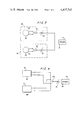
- FIG. 3 is a block diagram of the electrical circuitry used in the invention.
- FIG. 4 is a block diagram of an alternative electrical circuit used in the invention.
- the stereo camera system includes a support 1 made of any suitable material, such as metal, which carries a cradle 2 that is rigidly connected to and supports a motorized zoom lens 20.
- Mirrors 3 and 4 are attached to an L-shaped support 5, which is in turn, fixedly mounted on support 1.
- Mirrors 3 and 4 are arranged at an angle of 45° with respect to the optical axis of the zoom lens 10.
- Shaft 6b (FIG. 2) of gear 6 is supported from below the support 1 by means of the U-shaped support member 1c (FIG. 2), as is the shaft (not shown) of gear 7.
- Shaft 6b of gear 6 rests on the U-shaped member 1c, but if desired, suitable bearings can be provided for the shafts of gears 6 and 7.
- Hubs 6a and 7a carry L-shaped supports 8 and 9, respectively, on which is rigidly mounted mirrors 10 and 11, respectively.
- rotation of gear 6 in the direction shown by the arrow causes gear 7 to rotate in the opposite direction, and using the arrows shown in FIG. 1 for orientation, rotation of the gears 6 and 7 in the direction of the arrows will cause the mirrors 10 and 11 to move toward each other as viewed in FIG. 1, which will decrease the angle ⁇ included between mirrors 10 and 11.
- gears 6 and 7 are caused to rotate by means of gear 12, which meshes with gear 6.
- Gear 12 is connected to the shaft 13a of motor 13, which is in turn, carried by a support 14 mounted on support 1.
- the motorized zoom lens 20 has an operating element 22 which causes the lens to zoom to a larger focal length when the operating element 22 is rotated in one direction about the optical axis of the zoom lens 20, and to a smaller focal length when rotated in the opposite direction.
- Zoom lens 20 is a conventional motorized zoom lens, which has all of its movable optics within the interior of the zoom lens and is so constructed such that the front 21 of the zoom lens 20 does not move with respect to the rear 23 as the focal length is changed.
- Adjacent zoom lens 20 is motor 15, which is carried by support 16 mounted on the support 1.
- the shaft 15a of motor 15 carries a gear 17 which meshes with gear 18 that is rigidly connected to the operating element 22 of the zoom lens 20.
- the rear 23 of the zoom lens 20 has conventional attaching means for securing the zoom lens 20 to a camera body C, which is shown in dotted line in FIGS. 1 and 2.
- Camera body C may be the body of a still, motion picture or video camera of any format. Usually camera body C will be the body of a 16 mm or 35 mm motion picture camera or video camera.
- Motors 13 and 15 are commercially available, reversible DC motors that may be electrically connected as shown in FIG. 3.
- Each of the motors 13 and 15 has a self-contained armature 30, a three-way reversing switch 31 and a rheostat 32.
- Each of the motors 13 and 15 is grounded and connected to a grounded DC power source 33.
- switch 31 When the switch 31 is in a neutral position shown in FIG. 3, the motors 13 and 15 are in the OFF position.
- switch 31 changes the polarity of the motors 13 or 15.
- the switch 31 of each of the motors 13, 15 is moved to the upper position, as viewed in FIG.
- the motors 13, 15 turn in one direction, and when the switch 31 of motors 13, 15 is thrown to the lowermost position, as viewed in FIG. 3, the motors 13, 15 turn in the opposite direction.
- the rheostat 32 controls the speed of the motor 13, 15 and before use, the rheostat 32 will be adjusted so that the zooming of the zoom lens 20 is synchronized with the speed of rotation of gears 6, 7.
- FIG. 4 illustrates an alternative embodiment of the invention in which an external, three-way switch 40, and an external rheostat 41 replace the self-contained switch 31 and rheostat 32 of the motors 13, 15.
- Three-way switch 40 and rheostat 41 are in series with the power source 33, and the terminals of the switch 40 are wired directly into the appropriate terminals of the motors 13, 15. Moving the switch 40 to the uppermost terminal, causes the motor 13, 15 to turn in one direction and moving the switch 40 to the lowermost terminal causes the motors 13, 15 to turn in the opposite direction.
- the zoom lens 20 is secured in the position where the front element 21 is closely adjacent mirrors 3, 4; preferably the front element 21 is just out of contact with the mirrors 3, 4.
- camera C is attached to the zoom lens 20 and the zoom lens 20 is set at a desired focal length, usually the smallest focal length.
- a commercially available, motorized 16 mm format motion picture zoom lens having a range of focal lengths of from 12 mm to 120 L mm will be used, and hence the zoom lens 20 is preferably set at 12 mm.
- the zoom lens 20 is then focused on an object at a distance from camera C, after which it is zoomed to its 120 mm focal length by manually rotating gear 18.
- the two images viewed through the view-finder of camera C will be slightly out of focus. These images are aligned by manually rotating gears 6.7 in the direction shown by the arrows to move the mirrors 10, 11 inwardly.
- the included angle ⁇ corresponding to the smallest focal length is pre-set at substantially 90°, and that the adjustment procedure described above establishes the included angle ⁇ corresponding to the largest focal length of the zoom lens 20. This, in turn, establishes the degree of rotation of gears 6, 7 necessary to change the included angle ⁇ as the focal length changes between 12 mm to 120 mm.
- Rheostat 32 of motors 13, 15 is then adjusted to synchronize motors 13, 15 so that motor 13 decreases the included angle ⁇ from its predetermined value at the 12 mm focal length to the predetermined value at the 120 mm focal length as motor 15 zooms the zoom lens 20 to increase the focal length from 12 mm to 120 mm.
- motors 13, 15 are reversed, the included angle ⁇ will increase as the focal length decreases.
- the zoom lens 20 will deliver to each frame of film, a pair of side-by-side images of the same scene. These images will be in proper focus and alignment over the entire range of focal length of the zoom lens 20.
- the operator can thus keep the apparatus at a fixed position and can use the zoom lens 20 to take close-ups or to record in focus objects approaching the camera.
- the side-by-side images recorded on the film may be played back through conventional stereo projection equipment.
Abstract
Description
Claims (8)
Priority Applications (1)
| Application Number | Priority Date | Filing Date | Title |
|---|---|---|---|
| US06/432,029 US4437745A (en) | 1982-09-30 | 1982-09-30 | Three dimensional camera system |
Applications Claiming Priority (1)
| Application Number | Priority Date | Filing Date | Title |
|---|---|---|---|
| US06/432,029 US4437745A (en) | 1982-09-30 | 1982-09-30 | Three dimensional camera system |
Publications (1)
| Publication Number | Publication Date |
|---|---|
| US4437745A true US4437745A (en) | 1984-03-20 |
Family
ID=23714465
Family Applications (1)
| Application Number | Title | Priority Date | Filing Date |
|---|---|---|---|
| US06/432,029 Expired - Fee Related US4437745A (en) | 1982-09-30 | 1982-09-30 | Three dimensional camera system |
Country Status (1)
| Country | Link |
|---|---|
| US (1) | US4437745A (en) |
Cited By (35)
| Publication number | Priority date | Publication date | Assignee | Title |
|---|---|---|---|---|
| US4597741A (en) * | 1984-04-09 | 1986-07-01 | Honeywell | Apparatus for simulation of a field of view |
| US5086354A (en) * | 1989-02-27 | 1992-02-04 | Bass Robert E | Three dimensional optical viewing system |
| WO1993021736A1 (en) * | 1992-04-21 | 1993-10-28 | Cromwell Marketing Co., Inc. | Image splitter for security cameras and the like |
| US5293243A (en) * | 1992-04-21 | 1994-03-08 | Degnan Donald E | Image splitter for security cameras |
| GB2308199A (en) * | 1995-12-11 | 1997-06-18 | Thomson Multimedia Sa | Camera with variable deflection |
| US5671450A (en) * | 1994-07-21 | 1997-09-23 | Canon Kabushiki Kaisha | Stereo image forming adapter |
| US5727236A (en) * | 1994-06-30 | 1998-03-10 | Frazier; James A. | Wide angle, deep field, close focusing optical system |
| US5727239A (en) * | 1995-02-28 | 1998-03-10 | Olympus Optical Co., Ltd. | Photographing optical apparatus |
| US5828913A (en) * | 1995-06-06 | 1998-10-27 | Zanen; Pieter O. | Method for three dimensional measurement and imaging having focus-related convergence compensation |
| US5956180A (en) * | 1996-12-31 | 1999-09-21 | Bass; Robert | Optical viewing system for asynchronous overlaid images |
| US6212334B1 (en) | 1998-05-02 | 2001-04-03 | Cine Photo Tech, Inc. | Supplementary optical system for a camera |
| US6292634B1 (en) * | 1998-06-25 | 2001-09-18 | Minoru Inaba | Stereo camera |
| US6466746B2 (en) | 1998-06-26 | 2002-10-15 | Minoru Inaba | Stereo camera |
| US6616347B1 (en) | 2000-09-29 | 2003-09-09 | Robert Dougherty | Camera with rotating optical displacement unit |
| US6643396B1 (en) | 1999-06-11 | 2003-11-04 | Emile Hendriks | Acquisition of 3-D scenes with a single hand held camera |
| US6721500B2 (en) * | 2002-01-17 | 2004-04-13 | Zoran Perisic | Apparatus for three dimensional photography |
| US20040150728A1 (en) * | 1997-12-03 | 2004-08-05 | Shigeru Ogino | Image pick-up apparatus for stereoscope |
| US20060082879A1 (en) * | 2003-05-29 | 2006-04-20 | Takashi Miyoshi | Stereo optical module and stereo camera |
| CN100554878C (en) * | 2003-05-29 | 2009-10-28 | 奥林巴斯株式会社 | Stereo optical module and stereo camera |
| US20110188136A1 (en) * | 2010-01-29 | 2011-08-04 | Loreo Asia Ltd. | Focusing mount |
| US9294672B2 (en) * | 2014-06-20 | 2016-03-22 | Qualcomm Incorporated | Multi-camera system using folded optics free from parallax and tilt artifacts |
| US9374516B2 (en) | 2014-04-04 | 2016-06-21 | Qualcomm Incorporated | Auto-focus in low-profile folded optics multi-camera system |
| US9386222B2 (en) | 2014-06-20 | 2016-07-05 | Qualcomm Incorporated | Multi-camera system using folded optics free from parallax artifacts |
| US9383550B2 (en) | 2014-04-04 | 2016-07-05 | Qualcomm Incorporated | Auto-focus in low-profile folded optics multi-camera system |
| US9398264B2 (en) | 2012-10-19 | 2016-07-19 | Qualcomm Incorporated | Multi-camera system using folded optics |
| US9438889B2 (en) | 2011-09-21 | 2016-09-06 | Qualcomm Incorporated | System and method for improving methods of manufacturing stereoscopic image sensors |
| US9485495B2 (en) | 2010-08-09 | 2016-11-01 | Qualcomm Incorporated | Autofocus for stereo images |
| US9541740B2 (en) | 2014-06-20 | 2017-01-10 | Qualcomm Incorporated | Folded optic array camera using refractive prisms |
| US9549107B2 (en) | 2014-06-20 | 2017-01-17 | Qualcomm Incorporated | Autofocus for folded optic array cameras |
| US9819863B2 (en) | 2014-06-20 | 2017-11-14 | Qualcomm Incorporated | Wide field of view array camera for hemispheric and spherical imaging |
| US9832381B2 (en) | 2014-10-31 | 2017-11-28 | Qualcomm Incorporated | Optical image stabilization for thin cameras |
| US10013764B2 (en) | 2014-06-19 | 2018-07-03 | Qualcomm Incorporated | Local adaptive histogram equalization |
| US10178373B2 (en) | 2013-08-16 | 2019-01-08 | Qualcomm Incorporated | Stereo yaw correction using autofocus feedback |
| US10505431B1 (en) | 2017-03-06 | 2019-12-10 | Harold O. Hosea | Brushless dual rotor electromagnetic induction motor |
| WO2022116650A1 (en) * | 2020-12-03 | 2022-06-09 | 中兴通讯股份有限公司 | Camera module, electronic device and optical zoom method |
-
1982
- 1982-09-30 US US06/432,029 patent/US4437745A/en not_active Expired - Fee Related
Cited By (47)
| Publication number | Priority date | Publication date | Assignee | Title |
|---|---|---|---|---|
| US4597741A (en) * | 1984-04-09 | 1986-07-01 | Honeywell | Apparatus for simulation of a field of view |
| US5086354A (en) * | 1989-02-27 | 1992-02-04 | Bass Robert E | Three dimensional optical viewing system |
| US5589980A (en) * | 1989-02-27 | 1996-12-31 | Bass; Robert | Three dimensional optical viewing system |
| WO1993021736A1 (en) * | 1992-04-21 | 1993-10-28 | Cromwell Marketing Co., Inc. | Image splitter for security cameras and the like |
| US5293243A (en) * | 1992-04-21 | 1994-03-08 | Degnan Donald E | Image splitter for security cameras |
| US5727236A (en) * | 1994-06-30 | 1998-03-10 | Frazier; James A. | Wide angle, deep field, close focusing optical system |
| US5671450A (en) * | 1994-07-21 | 1997-09-23 | Canon Kabushiki Kaisha | Stereo image forming adapter |
| US5727239A (en) * | 1995-02-28 | 1998-03-10 | Olympus Optical Co., Ltd. | Photographing optical apparatus |
| US5883662A (en) * | 1995-06-06 | 1999-03-16 | Zanen; Pieter O. | Apparatus for three-dimensional measurement and imaging having focus-related convergance compensation |
| US5828913A (en) * | 1995-06-06 | 1998-10-27 | Zanen; Pieter O. | Method for three dimensional measurement and imaging having focus-related convergence compensation |
| GB2308199A (en) * | 1995-12-11 | 1997-06-18 | Thomson Multimedia Sa | Camera with variable deflection |
| US5956180A (en) * | 1996-12-31 | 1999-09-21 | Bass; Robert | Optical viewing system for asynchronous overlaid images |
| US20040150728A1 (en) * | 1997-12-03 | 2004-08-05 | Shigeru Ogino | Image pick-up apparatus for stereoscope |
| US6212334B1 (en) | 1998-05-02 | 2001-04-03 | Cine Photo Tech, Inc. | Supplementary optical system for a camera |
| US6292634B1 (en) * | 1998-06-25 | 2001-09-18 | Minoru Inaba | Stereo camera |
| US6466746B2 (en) | 1998-06-26 | 2002-10-15 | Minoru Inaba | Stereo camera |
| US6643396B1 (en) | 1999-06-11 | 2003-11-04 | Emile Hendriks | Acquisition of 3-D scenes with a single hand held camera |
| US6616347B1 (en) | 2000-09-29 | 2003-09-09 | Robert Dougherty | Camera with rotating optical displacement unit |
| US6721500B2 (en) * | 2002-01-17 | 2004-04-13 | Zoran Perisic | Apparatus for three dimensional photography |
| US20060082879A1 (en) * | 2003-05-29 | 2006-04-20 | Takashi Miyoshi | Stereo optical module and stereo camera |
| US7437066B2 (en) * | 2003-05-29 | 2008-10-14 | Olympus Corporation | Stereo optical module and stereo camera |
| CN100554878C (en) * | 2003-05-29 | 2009-10-28 | 奥林巴斯株式会社 | Stereo optical module and stereo camera |
| US20110188136A1 (en) * | 2010-01-29 | 2011-08-04 | Loreo Asia Ltd. | Focusing mount |
| US8608325B2 (en) * | 2010-01-29 | 2013-12-17 | Loreo Asia Ltd. | Focusing mount |
| US9485495B2 (en) | 2010-08-09 | 2016-11-01 | Qualcomm Incorporated | Autofocus for stereo images |
| US9438889B2 (en) | 2011-09-21 | 2016-09-06 | Qualcomm Incorporated | System and method for improving methods of manufacturing stereoscopic image sensors |
| US9838601B2 (en) | 2012-10-19 | 2017-12-05 | Qualcomm Incorporated | Multi-camera system using folded optics |
| US10165183B2 (en) | 2012-10-19 | 2018-12-25 | Qualcomm Incorporated | Multi-camera system using folded optics |
| US9398264B2 (en) | 2012-10-19 | 2016-07-19 | Qualcomm Incorporated | Multi-camera system using folded optics |
| US10178373B2 (en) | 2013-08-16 | 2019-01-08 | Qualcomm Incorporated | Stereo yaw correction using autofocus feedback |
| US9374516B2 (en) | 2014-04-04 | 2016-06-21 | Qualcomm Incorporated | Auto-focus in low-profile folded optics multi-camera system |
| US9383550B2 (en) | 2014-04-04 | 2016-07-05 | Qualcomm Incorporated | Auto-focus in low-profile folded optics multi-camera system |
| US9973680B2 (en) | 2014-04-04 | 2018-05-15 | Qualcomm Incorporated | Auto-focus in low-profile folded optics multi-camera system |
| US9860434B2 (en) | 2014-04-04 | 2018-01-02 | Qualcomm Incorporated | Auto-focus in low-profile folded optics multi-camera system |
| US10013764B2 (en) | 2014-06-19 | 2018-07-03 | Qualcomm Incorporated | Local adaptive histogram equalization |
| US9819863B2 (en) | 2014-06-20 | 2017-11-14 | Qualcomm Incorporated | Wide field of view array camera for hemispheric and spherical imaging |
| US9843723B2 (en) | 2014-06-20 | 2017-12-12 | Qualcomm Incorporated | Parallax free multi-camera system capable of capturing full spherical images |
| US9854182B2 (en) | 2014-06-20 | 2017-12-26 | Qualcomm Incorporated | Folded optic array camera using refractive prisms |
| US9733458B2 (en) | 2014-06-20 | 2017-08-15 | Qualcomm Incorporated | Multi-camera system using folded optics free from parallax artifacts |
| US9549107B2 (en) | 2014-06-20 | 2017-01-17 | Qualcomm Incorporated | Autofocus for folded optic array cameras |
| US9541740B2 (en) | 2014-06-20 | 2017-01-10 | Qualcomm Incorporated | Folded optic array camera using refractive prisms |
| US10084958B2 (en) | 2014-06-20 | 2018-09-25 | Qualcomm Incorporated | Multi-camera system using folded optics free from parallax and tilt artifacts |
| US9386222B2 (en) | 2014-06-20 | 2016-07-05 | Qualcomm Incorporated | Multi-camera system using folded optics free from parallax artifacts |
| US9294672B2 (en) * | 2014-06-20 | 2016-03-22 | Qualcomm Incorporated | Multi-camera system using folded optics free from parallax and tilt artifacts |
| US9832381B2 (en) | 2014-10-31 | 2017-11-28 | Qualcomm Incorporated | Optical image stabilization for thin cameras |
| US10505431B1 (en) | 2017-03-06 | 2019-12-10 | Harold O. Hosea | Brushless dual rotor electromagnetic induction motor |
| WO2022116650A1 (en) * | 2020-12-03 | 2022-06-09 | 中兴通讯股份有限公司 | Camera module, electronic device and optical zoom method |
Similar Documents
| Publication | Publication Date | Title |
|---|---|---|
| US4437745A (en) | Three dimensional camera system | |
| US5532777A (en) | Single lens apparatus for three-dimensional imaging having focus-related convergence compensation | |
| US4485406A (en) | Film video player with zoom and scan | |
| JP2880131B2 (en) | Stereo camera | |
| US4436369A (en) | Stereoscopic lens system | |
| US7388598B2 (en) | 3D camera system and method | |
| JP2001022014A (en) | Stereo camera | |
| JP2002027496A (en) | Image pickup lens unit, image pickup apparatus and image pickup system | |
| EP0500910B1 (en) | Device and method for stereoscopic viewing of slides and prints | |
| US4678298A (en) | Method and apparatus for three-dimensional photography | |
| EP1303788A1 (en) | Multiplexed motion picture camera | |
| US4437126A (en) | Electronic cinema camera | |
| US3867022A (en) | Cineconversion machine | |
| US4568160A (en) | Process and apparatus for 3-dimensional moving pictures | |
| US4510529A (en) | Electronic cinema camera | |
| US4915497A (en) | Stereoscopic motion picture apparatus with horizontal film movement | |
| US4100572A (en) | Optical method and apparatus for carrying out the method | |
| CN212745690U (en) | Projection imaging system | |
| US3038370A (en) | Apparatus for photographing and projecting a picture of a great width | |
| US4825234A (en) | Cylindrical all around stereophotograph (photo-statue) and a cylindrical continuous photography with lenticule and its equipment | |
| JPH08111798A (en) | Three-direction monitoring image pickup camera device | |
| US2927508A (en) | Multiplex camera for photographing adjacent scenes on separate image recording means | |
| JPH11205818A (en) | Stereoscopic video system and stereoscopic video photographing adaptor | |
| US2519988A (en) | Method and device for photographic scanning | |
| JPH09331476A (en) | Camera back replacement camera |
Legal Events
| Date | Code | Title | Description |
|---|---|---|---|
| MAFP | Maintenance fee payment |
Free format text: PAYMENT OF MAINTENANCE FEE, 4TH YR, SMALL ENTITY, PL 97-247 (ORIGINAL EVENT CODE: M273); ENTITY STATUS OF PATENT OWNER: SMALL ENTITY Year of fee payment: 4 |
|
| MAFP | Maintenance fee payment |
Free format text: PAYMENT OF MAINTENANCE FEE, 8TH YR, SMALL ENTITY, PL 97-247 (ORIGINAL EVENT CODE: M274); ENTITY STATUS OF PATENT OWNER: SMALL ENTITY Year of fee payment: 8 |
|
| FEPP | Fee payment procedure |
Free format text: PAYOR NUMBER ASSIGNED (ORIGINAL EVENT CODE: ASPN); ENTITY STATUS OF PATENT OWNER: SMALL ENTITY |
|
| FEPP | Fee payment procedure |
Free format text: MAINTENANCE FEE REMINDER MAILED (ORIGINAL EVENT CODE: REM.); ENTITY STATUS OF PATENT OWNER: SMALL ENTITY |
|
| LAPS | Lapse for failure to pay maintenance fees | ||
| FP | Lapsed due to failure to pay maintenance fee |
Effective date: 19960320 |
|
| STCH | Information on status: patent discontinuation |
Free format text: PATENT EXPIRED DUE TO NONPAYMENT OF MAINTENANCE FEES UNDER 37 CFR 1.362 |