US4420085A - Stand up organizer - Google Patents
Stand up organizer Download PDFInfo
- Publication number
- US4420085A US4420085A US06/339,537 US33953782A US4420085A US 4420085 A US4420085 A US 4420085A US 33953782 A US33953782 A US 33953782A US 4420085 A US4420085 A US 4420085A
- Authority
- US
- United States
- Prior art keywords
- ampoule
- syringe
- recess
- cap
- tray
- Prior art date
- Legal status (The legal status is an assumption and is not a legal conclusion. Google has not performed a legal analysis and makes no representation as to the accuracy of the status listed.)
- Expired - Fee Related
Links
Images

Classifications
-
- A—HUMAN NECESSITIES
- A61—MEDICAL OR VETERINARY SCIENCE; HYGIENE
- A61M—DEVICES FOR INTRODUCING MEDIA INTO, OR ONTO, THE BODY; DEVICES FOR TRANSDUCING BODY MEDIA OR FOR TAKING MEDIA FROM THE BODY; DEVICES FOR PRODUCING OR ENDING SLEEP OR STUPOR
- A61M5/00—Devices for bringing media into the body in a subcutaneous, intra-vascular or intramuscular way; Accessories therefor, e.g. filling or cleaning devices, arm-rests
- A61M5/002—Packages specially adapted therefor, e.g. for syringes or needles, kits for diabetics
-
- A—HUMAN NECESSITIES
- A61—MEDICAL OR VETERINARY SCIENCE; HYGIENE
- A61B—DIAGNOSIS; SURGERY; IDENTIFICATION
- A61B50/00—Containers, covers, furniture or holders specially adapted for surgical or diagnostic appliances or instruments, e.g. sterile covers
- A61B50/20—Holders specially adapted for surgical or diagnostic appliances or instruments
- A61B50/22—Racks
-
- A—HUMAN NECESSITIES
- A61—MEDICAL OR VETERINARY SCIENCE; HYGIENE
- A61B—DIAGNOSIS; SURGERY; IDENTIFICATION
- A61B50/00—Containers, covers, furniture or holders specially adapted for surgical or diagnostic appliances or instruments, e.g. sterile covers
- A61B50/30—Containers specially adapted for packaging, protecting, dispensing, collecting or disposing of surgical or diagnostic appliances or instruments
- A61B50/33—Trays
Definitions
- the present invention relates to organizers for medical procedures.
- a principal feature of the present invention is the provision of an organizer for a medical procedure.
- the organizer of the invention comprises, a syringe having a hollow barrel, and an elongated cap releasably attached to a distal portion of the syringe.
- the organizer has a tray having an upper wall, with the upper wall having an elongated groove to receive the syringe in a lay-flat configuration.
- the upper wall has a syringe recess shaped to releasably receive a distal end of the cap.
- the organizer may have an ampoule having a hollow body portion, and the upper wall of the tray may have an elongated groove to receive the ampoule in a lay-flat condition.
- the upper wall of the tray may have an ampoule recess adjacent an end of the groove for the ampoule.
- a feature of the present invention is that the syringe recess retains the syringe in an upright position.
- the syringe may be removed from the cap for use of the syringe during the medical procedure, after which the syringe may be placed back into the cap.
- tray retains the syringe in a convenient position for use during the medical procedure.
- top of the ampoule may be broken, and the body portion of the ampoule may be placed in the ampoule recess to retain the ampoule in an upright position.
- a feature of the present invention is that the tray retains the ampoule in a convenient configuration for use during the medical procedure.
- a further feature of the invention is that the syringe may be utilized to remove liquid contents from the ampoule.
- Still another feature of the invention is that the syringe recess may be placed adjacent an end of the ampoule groove, such that the syringe is in a convenient position for use with the ampoule.
- tray organizes the components for convenient use during the medical procedure.
- a further feature of the invention is that the tray may have a metal base to prevent tipping of the tray during use.
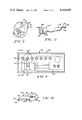
- FIG. 1 is a top plan view of an organizer tray which illustrates the tray components of a syringe and an ampoule;
- FIG. 2 is a fragmentary plan view illustrating an ampoule groove in an upper wall of the tray with the ampoule removed;
- FIG. 3 is a fragmentary sectional view taken substantially as indicated along the line 3--3 of FIG. 2;
- FIG. 4 is a fragmentary perspective view illustrating the retention of the ampoule in an upright position in a recess of the tray upper wall;
- FIG. 5 is a fragmentary sectional view of a syringe recess taken substantially as indicated along the line 5--5 of FIG. 1;
- FIG. 6 is a fragmentary perspective view illustrating the use of the syringe recess to place the syringe in an upright position in the tray;
- FIG. 7 is a fragmentary plan view of another embodiment of the present invention.
- FIG. 8 is a fragmentary sectional view taken subtantially as indicated along the line 8--8 of FIG. 7;
- FIG. 9 is a top plan view of another embodiment of the organizer of the present invention.
- FIG. 10 is a sectional view taken substantially as indicated along the line 10--10 of FIG. 9.
- a stand up organizer generally designated 20 comprising a tray 22 of suitable plastic material having a plurality of recesses 24 in an upper wall 26 of the tray 22 to receive a plurality of components, such as a syringe 28 and an ampoule 30.
- the syringe 28 may be of the type having an elongated hollow barrel 32, a plunger 34 slidably received in the barrel 32, a tip 36 extending distally from the barrel 32, and a hub 38 attached to the tip 36, with the hub 38 having an elongated distally extending needle (not shown).
- an elongated hollow cap 40 is releasably attached to the hub 38 at a distal portion 42 of the syringe 28 in order to receive and cover the syringe needle.
- the ampoule 30 has a cylindrical hollow body portion 44 to retain liquid contents in the ampoule 30, and a top 46 which is broken from the ampoule 30 in order to expose the liquid contents during use of the tray 22.
- the upper wall 26 of the tray 22 has an elongated groove 48 to receive the syringe 28 in a lay-flat configuration in the tray 22 prior to use of the tray 22.
- the tray 22 has a syringe recess 50 having a plurality of bosses 52, such as three, defining a central opening 54 to receive a distal end of the syringe cap 40.
- the syringe 28 may be removed from the groove 48, and, as shown in FIG. 6, the distal end of the cap 40 may be positioned in the opening 54, such that the bosses 52 frictionally engage the distal end of the cap 40 and retain the syringe 28 in an upright position in the tray 22.
- the syringe 28 may be removed from the cap 40 in order to expose the needle of the syringe 28, and, after use of the syringe 28, the syringe 28 may be reinserted into the cap 40 in order to retain the syringe 28 again in an upright position.
- the upper wall 26 of the tray 22 also has an elongated groove 56 to receive the ampoule 30 in a lay-flat configuration prior to use of the tray 22.
- the upper wall 26 of the tray 22 has a generally cylindrical ampoule recess 58 adjacent one end 60 of the groove 56 to snugly receive the lower part of the ampoule body portion 44.
- the ampoule 30 may be removed from the groove 56, and the body portion 44 of the ampoule 30 may be placed in the recess 58 in order to retain the ampoule 30 in an upright configuration.
- the top 46 of the ampoule 30 may be broken prior to placing the ampoule 30 in the upright position in order to expose the liquid contents in the ampoule 30.
- the syringe 28 may be placed in an upright position in the recess 50, and the ampoule 30 may be placed in an upright position in the recess 58.
- the syringe 28 may be removed from the cap 40, and the needle of the syringe 28 may be placed through the broken top of the ampoule 30 in order to remove the liquid contents from the ampoule 30 through manipulation of the syringe 28.
- the syringe 28 may be again placed in th cap 40 in order to retain the syringe 28 in an upright position.
- the tray 22 of the invention minimizes the amount of space that is required for the medical procedure, and organizes the components for use in a convenient manner in order to simplify the procedure.
- FIGS. 7 and 8 Another embodiment of the present invention is illustrated in FIGS. 7 and 8, in which like reference numerals designate like parts.
- the upper wall 26 of the tray 22 also has an ampoule recess 58 adjacent the one end 60 of the groove 56.
- the recess 58 has a plurality of bosses 62 defining a central opening 64 to receive the lower part of the ampoule with the ampoule in an upright position.
- the bosses 62 frictionally engage against the body portion of the ampoule in order to retain the ampoule 30 in the upright position.
- the tray 22 has a plurality of grooves 56 to retain ampoules in a lay-flat condition, and associated recesses 58 at one end 60 of the grooves 56 to retain the ampoules in an upright position.
- the tray 22 has a plurality of syringe recesses 50 to receive the cap associated with the syringe, and retain the syringes in an upright position.
- the syringe recesses 50 may be located adjacent the recesses 58 for the ampoules in order to organize one syringe in an upright position for use with each associated ampoule which is in the grooves 56 aligned with the recesses 50.
- the tray 22 has a pair of sidewalls 66 extending downwardly from opposed sides of the tray upper wall 26.
- the sidewalls 66 have an outwardly directed flange 68 at a lower end of the sidewalls 66.
- the tray 22 has a base 80 of relatively heavy material, such as a suitable metal, with the base 80 having a pair of opposted C-shaped flanges 82 to receive the flanges 68. In this configuration, the base 80 is attached to a lower portion of the tray 22, and the relatively heavy base 80 prevents tipping of the tray 22 during use.
Abstract
Description
Claims (5)
Priority Applications (2)
| Application Number | Priority Date | Filing Date | Title |
|---|---|---|---|
| US06/339,537 US4420085A (en) | 1982-01-15 | 1982-01-15 | Stand up organizer |
| CA000419607A CA1198092A (en) | 1982-01-15 | 1983-01-17 | Stand up organizer |
Applications Claiming Priority (1)
| Application Number | Priority Date | Filing Date | Title |
|---|---|---|---|
| US06/339,537 US4420085A (en) | 1982-01-15 | 1982-01-15 | Stand up organizer |
Publications (1)
| Publication Number | Publication Date |
|---|---|
| US4420085A true US4420085A (en) | 1983-12-13 |
Family
ID=23329482
Family Applications (1)
| Application Number | Title | Priority Date | Filing Date |
|---|---|---|---|
| US06/339,537 Expired - Fee Related US4420085A (en) | 1982-01-15 | 1982-01-15 | Stand up organizer |
Country Status (2)
| Country | Link |
|---|---|
| US (1) | US4420085A (en) |
| CA (1) | CA1198092A (en) |
Cited By (77)
| Publication number | Priority date | Publication date | Assignee | Title |
|---|---|---|---|---|
| US4667837A (en) * | 1986-06-05 | 1987-05-26 | International Medical Industries, Incorporated | Tamper proof cap |
| US4767008A (en) * | 1987-11-02 | 1988-08-30 | Warnecke Armand E | Injection monitor appliance |
| US4836374A (en) * | 1988-09-02 | 1989-06-06 | The Stanley Works | Fitted tool case |
| US4846803A (en) * | 1988-01-11 | 1989-07-11 | Emerson Debora L | Hypodermic needle-cap handling device |
| EP0361139A1 (en) * | 1988-09-26 | 1990-04-04 | Hammerlit Gmbh | Syringe tray |
| US4915233A (en) * | 1988-11-02 | 1990-04-10 | The Regents Of The University Of California | Dental anesthesia organizer |
| US5099992A (en) * | 1989-11-03 | 1992-03-31 | Bent Heimreid | Arrangement in connection with a rack for orderly storage and/or for keeping syringes with a luer tip ready for use |
| US5199567A (en) * | 1991-05-08 | 1993-04-06 | Centrix, Inc. | Single patient dose dental cartridge tray and organizing system |
| US5299687A (en) * | 1992-12-22 | 1994-04-05 | Sage Products, Inc. | Cannula adaptor delivery system |
| US5514335A (en) * | 1993-10-25 | 1996-05-07 | Minnesota Mining And Manufacturing Company | Blood oxygenation system and reservoir and method of manufacture |
| FR2747030A1 (en) * | 1996-04-05 | 1997-10-10 | Ellios Bio Media | Packaging for medical sample syringe |
| US5868250A (en) * | 1996-09-26 | 1999-02-09 | Brackett; Fred | Tray for holding medical instruments |
| US6306346B1 (en) | 1999-02-10 | 2001-10-23 | Terumo Cardiovascular Systems Corporation | Self-contained pack assembly for an extracorporeal blood circuit |
| US6468473B1 (en) | 1999-02-10 | 2002-10-22 | Terumo Cardiovascular Systems Corporation | Self-contained pack assembly for an extracorporeal blood circuit |
| US20050101905A1 (en) * | 1997-09-03 | 2005-05-12 | Safer Sleep Limited | Coding of syringes to monitor their use |
| US20070185495A1 (en) * | 2006-01-30 | 2007-08-09 | Howmedica International S. De R. L. | Plug-in syringe stand |
| US20080125722A1 (en) * | 2006-09-15 | 2008-05-29 | Howmedica International S. De R.L. | Syringe and stand |
| US7762988B1 (en) | 2001-05-11 | 2010-07-27 | Medical Device Engineering, Llc | Tamper evident end cap assembly for a loaded syringe and process |
| US8348895B1 (en) | 2010-05-27 | 2013-01-08 | Medical Device Engineering, LLC. | Tamper evident cap assembly |
| EP2574355A1 (en) * | 2011-09-27 | 2013-04-03 | Sanofi-Aventis Deutschland GmbH | Package for a medicament delivery device |
| EP2777683A1 (en) * | 2011-11-10 | 2014-09-17 | Panasonic Healthcare Co., Ltd. | Storage case for pharmaceutical preparation syringe unit |
| US8864708B1 (en) | 2010-12-03 | 2014-10-21 | Medical Device Engineering, LLC. | Tamper indicating closure assembly |
| US20150129456A1 (en) * | 2006-09-12 | 2015-05-14 | Vidacare Corporation | Vertebral access system and methods |
| EP2878320A1 (en) * | 2013-11-28 | 2015-06-03 | Sanofi-Aventis Deutschland GmbH | Boot remover |
| USD743250S1 (en) * | 2013-12-24 | 2015-11-17 | Hitachi Chemical Company, Ltd. | Packaging container |
| US9199749B1 (en) | 2011-04-26 | 2015-12-01 | Medical Device Engineering, LLC. | Assembly and system for connecting a closure to a syringe |
| US9311592B1 (en) | 2012-08-31 | 2016-04-12 | Medical Device Engineering, LLC. | Support and closure assembly for discharge port of a syringe and tracking system therefore |
| US9402967B1 (en) | 2010-05-27 | 2016-08-02 | Medical Device Engineering, Llc | Tamper evident cap assembly |
| US9821152B1 (en) | 2013-03-04 | 2017-11-21 | Medical Device Engineering, LLC. | Closure assembly |
| US9855191B1 (en) | 2013-12-09 | 2018-01-02 | Jonathan J. Vitello | Tamper evident shield assembly with tracking |
| US10111725B2 (en) * | 2016-09-20 | 2018-10-30 | Rocktape, Inc. | Massage tool case |
| US10166343B1 (en) | 2015-03-13 | 2019-01-01 | Timothy Brandon Hunt | Noise evident tamper cap |
| US10166332B2 (en) | 2002-05-31 | 2019-01-01 | Teleflex Medical Devices S.À R.L. | Apparatus to inject fluids into bone marrow and other target sites |
| US10166347B1 (en) | 2014-07-18 | 2019-01-01 | Patrick Vitello | Closure assembly for a medical device |
| US10207099B1 (en) | 2014-02-21 | 2019-02-19 | Patrick Vitello | Closure assembly for medical fitting |
| US10245010B2 (en) | 2002-05-31 | 2019-04-02 | Teleflex Medical Devices S.A.R.L | Assembly for coupling powered driver with intraosseous device |
| US10300263B1 (en) | 2015-02-27 | 2019-05-28 | Timothy Brandon Hunt | Closure assembly for a medical connector |
| US10307548B1 (en) | 2016-12-14 | 2019-06-04 | Timothy Brandon Hunt | Tracking system and method for medical devices |
| US10315024B1 (en) | 2015-03-19 | 2019-06-11 | Patick Vitello | Torque limiting closure assembly |
| US10595896B2 (en) | 2002-05-31 | 2020-03-24 | Teleflex Life Sciences Limited | Apparatus for accessing bone marrow including depth control mechanism |
| US10722384B2 (en) * | 2017-03-01 | 2020-07-28 | Nordson Corporation | Medical material mixer and transfer apparatus and method for using the same |
| CN111481389A (en) * | 2020-04-26 | 2020-08-04 | 华巧芬 | Medical dressing change box and dressing change device comprising same |
| CN111513961A (en) * | 2020-04-26 | 2020-08-11 | 华巧芬 | Medical dressing bracket |
| US10758684B1 (en) | 2017-03-03 | 2020-09-01 | Jonathan J. Vitello | Tamper evident assembly |
| US10806491B2 (en) | 2002-05-31 | 2020-10-20 | Teleflex Life Sciences Limited | Vascular access kits and methods |
| USD903865S1 (en) | 2018-11-19 | 2020-12-01 | International Medical Industries, Inc. | Self-righting tip cap |
| US10888672B1 (en) | 2017-04-06 | 2021-01-12 | International Medical Industries, Inc. | Tamper evident closure assembly for a medical device |
| US10898659B1 (en) | 2017-05-19 | 2021-01-26 | International Medical Industries Inc. | System for handling and dispensing a plurality of products |
| US10912898B1 (en) | 2014-02-03 | 2021-02-09 | Medical Device Engineering Llc | Tamper evident cap for medical fitting |
| US10933202B1 (en) | 2017-05-19 | 2021-03-02 | International Medical Industries Inc. | Indicator member of low strength resistance for a tamper evident closure |
| US10953162B1 (en) | 2016-12-28 | 2021-03-23 | Timothy Brandon Hunt | Tamper evident closure assembly |
| US10973532B2 (en) | 2002-05-31 | 2021-04-13 | Teleflex Life Sciences Limited | Powered drivers, intraosseous devices and methods to access bone marrow |
| US10973545B2 (en) | 2002-05-31 | 2021-04-13 | Teleflex Life Sciences Limited | Powered drivers, intraosseous devices and methods to access bone marrow |
| US11040149B1 (en) | 2017-03-30 | 2021-06-22 | International Medical Industries | Tamper evident closure assembly for a medical device |
| US11097071B1 (en) | 2016-12-14 | 2021-08-24 | International Medical Industries Inc. | Tamper evident assembly |
| US11266441B2 (en) | 2002-05-31 | 2022-03-08 | Teleflex Life Sciences Limited | Penetrator assembly for accessing bone marrow |
| US11278681B1 (en) | 2018-02-20 | 2022-03-22 | Robert Banik | Tamper evident adaptor closure |
| USD948713S1 (en) | 2019-09-03 | 2022-04-12 | International Medical Industries, Inc. | Asymmetrical self righting tip cap |
| US11324521B2 (en) | 2002-05-31 | 2022-05-10 | Teleflex Life Sciences Limited | Apparatus and method to access bone marrow |
| US11337728B2 (en) | 2002-05-31 | 2022-05-24 | Teleflex Life Sciences Limited | Powered drivers, intraosseous devices and methods to access bone marrow |
| US11351299B2 (en) * | 2019-03-15 | 2022-06-07 | Chiesi Farmaceutici S.P.A. | System comprising a pre-fillable syringe and a package for the pre-fillable syringe |
| US11357588B1 (en) | 2019-11-25 | 2022-06-14 | Patrick Vitello | Needle packaging and disposal assembly |
| US11369733B2 (en) * | 2019-03-15 | 2022-06-28 | Chiesi Farmaceutici S.P.A. | System comprising a pre-fillable syringe and a package for the pre-fillable syringe |
| US11413406B1 (en) | 2018-03-05 | 2022-08-16 | Jonathan J. Vitello | Tamper evident assembly |
| US11426328B1 (en) | 2018-08-31 | 2022-08-30 | Alexander Ollmann | Closure for a medical container |
| US11471610B1 (en) | 2018-10-18 | 2022-10-18 | Robert Banik | Asymmetrical closure for a medical device |
| US11523970B1 (en) | 2020-08-28 | 2022-12-13 | Jonathan Vitello | Tamper evident shield |
| US11541180B1 (en) | 2017-12-21 | 2023-01-03 | Patrick Vitello | Closure assembly having a snap-fit construction |
| US11690994B1 (en) | 2018-07-13 | 2023-07-04 | Robert Banik | Modular medical connector |
| US11697527B1 (en) | 2019-09-11 | 2023-07-11 | Logan Hendren | Tamper evident closure assembly |
| US11771439B2 (en) | 2007-04-04 | 2023-10-03 | Teleflex Life Sciences Limited | Powered driver |
| US11779520B1 (en) | 2018-07-02 | 2023-10-10 | Patrick Vitello | Closure for a medical dispenser including a one-piece tip cap |
| US11793987B1 (en) | 2018-07-02 | 2023-10-24 | Patrick Vitello | Flex tec closure assembly for a medical dispenser |
| US11857751B1 (en) | 2018-07-02 | 2024-01-02 | International Medical Industries Inc. | Assembly for a medical connector |
| US11872187B1 (en) | 2020-12-28 | 2024-01-16 | Jonathan Vitello | Tamper evident seal for a vial cover |
| US11904149B1 (en) | 2020-02-18 | 2024-02-20 | Jonathan Vitello | Oral tamper evident closure with retained indicator |
| US11911339B1 (en) | 2019-08-15 | 2024-02-27 | Peter Lehel | Universal additive port cap |
Citations (2)
| Publication number | Priority date | Publication date | Assignee | Title |
|---|---|---|---|---|
| US2313905A (en) * | 1942-05-16 | 1943-03-16 | Wallin Loren | Hypodermic needle rack |
| US3013656A (en) * | 1958-05-15 | 1961-12-19 | Cordis Corp | Disposable medical trays |
-
1982
- 1982-01-15 US US06/339,537 patent/US4420085A/en not_active Expired - Fee Related
-
1983
- 1983-01-17 CA CA000419607A patent/CA1198092A/en not_active Expired
Patent Citations (2)
| Publication number | Priority date | Publication date | Assignee | Title |
|---|---|---|---|---|
| US2313905A (en) * | 1942-05-16 | 1943-03-16 | Wallin Loren | Hypodermic needle rack |
| US3013656A (en) * | 1958-05-15 | 1961-12-19 | Cordis Corp | Disposable medical trays |
Cited By (103)
| Publication number | Priority date | Publication date | Assignee | Title |
|---|---|---|---|---|
| US4667837A (en) * | 1986-06-05 | 1987-05-26 | International Medical Industries, Incorporated | Tamper proof cap |
| US4767008A (en) * | 1987-11-02 | 1988-08-30 | Warnecke Armand E | Injection monitor appliance |
| US4846803A (en) * | 1988-01-11 | 1989-07-11 | Emerson Debora L | Hypodermic needle-cap handling device |
| US4836374A (en) * | 1988-09-02 | 1989-06-06 | The Stanley Works | Fitted tool case |
| US5007535A (en) * | 1988-09-26 | 1991-04-16 | Hammerlit Gmbh | Syringe tray |
| EP0361139A1 (en) * | 1988-09-26 | 1990-04-04 | Hammerlit Gmbh | Syringe tray |
| US4915233A (en) * | 1988-11-02 | 1990-04-10 | The Regents Of The University Of California | Dental anesthesia organizer |
| US5099992A (en) * | 1989-11-03 | 1992-03-31 | Bent Heimreid | Arrangement in connection with a rack for orderly storage and/or for keeping syringes with a luer tip ready for use |
| US5199567A (en) * | 1991-05-08 | 1993-04-06 | Centrix, Inc. | Single patient dose dental cartridge tray and organizing system |
| US5299687A (en) * | 1992-12-22 | 1994-04-05 | Sage Products, Inc. | Cannula adaptor delivery system |
| US5514335A (en) * | 1993-10-25 | 1996-05-07 | Minnesota Mining And Manufacturing Company | Blood oxygenation system and reservoir and method of manufacture |
| FR2747030A1 (en) * | 1996-04-05 | 1997-10-10 | Ellios Bio Media | Packaging for medical sample syringe |
| US5868250A (en) * | 1996-09-26 | 1999-02-09 | Brackett; Fred | Tray for holding medical instruments |
| US20050101905A1 (en) * | 1997-09-03 | 2005-05-12 | Safer Sleep Limited | Coding of syringes to monitor their use |
| US6468473B1 (en) | 1999-02-10 | 2002-10-22 | Terumo Cardiovascular Systems Corporation | Self-contained pack assembly for an extracorporeal blood circuit |
| US6811749B2 (en) | 1999-02-10 | 2004-11-02 | Terumo Cardiovascular Systems Corporation | Self-contained pack assembly for an extracorporeal blood circuit |
| US6306346B1 (en) | 1999-02-10 | 2001-10-23 | Terumo Cardiovascular Systems Corporation | Self-contained pack assembly for an extracorporeal blood circuit |
| US7762988B1 (en) | 2001-05-11 | 2010-07-27 | Medical Device Engineering, Llc | Tamper evident end cap assembly for a loaded syringe and process |
| US10973532B2 (en) | 2002-05-31 | 2021-04-13 | Teleflex Life Sciences Limited | Powered drivers, intraosseous devices and methods to access bone marrow |
| US10595896B2 (en) | 2002-05-31 | 2020-03-24 | Teleflex Life Sciences Limited | Apparatus for accessing bone marrow including depth control mechanism |
| US10806491B2 (en) | 2002-05-31 | 2020-10-20 | Teleflex Life Sciences Limited | Vascular access kits and methods |
| US10245010B2 (en) | 2002-05-31 | 2019-04-02 | Teleflex Medical Devices S.A.R.L | Assembly for coupling powered driver with intraosseous device |
| US10166332B2 (en) | 2002-05-31 | 2019-01-01 | Teleflex Medical Devices S.À R.L. | Apparatus to inject fluids into bone marrow and other target sites |
| US11266441B2 (en) | 2002-05-31 | 2022-03-08 | Teleflex Life Sciences Limited | Penetrator assembly for accessing bone marrow |
| US10973545B2 (en) | 2002-05-31 | 2021-04-13 | Teleflex Life Sciences Limited | Powered drivers, intraosseous devices and methods to access bone marrow |
| US11065382B2 (en) | 2002-05-31 | 2021-07-20 | Teleflex Life Sciences Limited | Apparatus to inject fluids into bone marrow and other target sites |
| US11103282B1 (en) | 2002-05-31 | 2021-08-31 | Teleflex Life Sciences Limited | Powered drivers, intraosseous devices and methods to access bone marrow |
| US11234683B2 (en) | 2002-05-31 | 2022-02-01 | Teleflex Life Sciences Limited | Assembly for coupling powered driver with intraosseous device |
| US11337728B2 (en) | 2002-05-31 | 2022-05-24 | Teleflex Life Sciences Limited | Powered drivers, intraosseous devices and methods to access bone marrow |
| US11324521B2 (en) | 2002-05-31 | 2022-05-10 | Teleflex Life Sciences Limited | Apparatus and method to access bone marrow |
| US11291472B2 (en) | 2002-05-31 | 2022-04-05 | Teleflex Life Sciences Limited | Powered drivers, intraosseous devices and methods to access bone marrow |
| US20110015640A1 (en) * | 2006-01-30 | 2011-01-20 | Stryker Leibinger Gmbh & Co. Kg | Syringe |
| US8945134B2 (en) | 2006-01-30 | 2015-02-03 | Stryker Leibinger Gmbh & Co. Kg | Syringe and stand |
| US8403936B2 (en) * | 2006-01-30 | 2013-03-26 | Stryker Leibinger Gmbh & Co. Kg | Syringe and stand |
| US8303599B2 (en) | 2006-01-30 | 2012-11-06 | Stryker Leibinger Gmbh & Co. Kg | Syringe |
| US20070225654A1 (en) * | 2006-01-30 | 2007-09-27 | Howmedica International S. De R.L. | Syringe and stand |
| JP2007216009A (en) * | 2006-01-30 | 2007-08-30 | Howmedica Internatl S De Rl | Syringe and stand |
| US20070185495A1 (en) * | 2006-01-30 | 2007-08-09 | Howmedica International S. De R. L. | Plug-in syringe stand |
| US11426249B2 (en) | 2006-09-12 | 2022-08-30 | Teleflex Life Sciences Limited | Vertebral access system and methods |
| US20150129456A1 (en) * | 2006-09-12 | 2015-05-14 | Vidacare Corporation | Vertebral access system and methods |
| US20080125722A1 (en) * | 2006-09-15 | 2008-05-29 | Howmedica International S. De R.L. | Syringe and stand |
| US11771439B2 (en) | 2007-04-04 | 2023-10-03 | Teleflex Life Sciences Limited | Powered driver |
| US8348895B1 (en) | 2010-05-27 | 2013-01-08 | Medical Device Engineering, LLC. | Tamper evident cap assembly |
| US9402967B1 (en) | 2010-05-27 | 2016-08-02 | Medical Device Engineering, Llc | Tamper evident cap assembly |
| US10183129B1 (en) | 2010-12-03 | 2019-01-22 | Medical Device Engineering, Llc | Tamper indicating closure assembly |
| US9463310B1 (en) | 2010-12-03 | 2016-10-11 | Medical Device Engineering, LLC. | Tamper indicating closure assembly |
| US8864707B1 (en) | 2010-12-03 | 2014-10-21 | Medical Device Engineering, LLC. | Tamper indicating closure assembly |
| US8864708B1 (en) | 2010-12-03 | 2014-10-21 | Medical Device Engineering, LLC. | Tamper indicating closure assembly |
| US9199749B1 (en) | 2011-04-26 | 2015-12-01 | Medical Device Engineering, LLC. | Assembly and system for connecting a closure to a syringe |
| WO2013045346A1 (en) * | 2011-09-27 | 2013-04-04 | Sanofi-Aventis Deutschland Gmbh | Package for a medicament delivery device |
| EP2574355A1 (en) * | 2011-09-27 | 2013-04-03 | Sanofi-Aventis Deutschland GmbH | Package for a medicament delivery device |
| JP2014526358A (en) * | 2011-09-27 | 2014-10-06 | サノフィ−アベンティス・ドイチュラント・ゲゼルシャフト・ミット・ベシュレンクテル・ハフツング | Package for drug delivery device |
| US20140224688A1 (en) * | 2011-09-27 | 2014-08-14 | Sanofi-Aventis Deutschland Gmbh | Package for a medicament delivery device |
| EP2777683A4 (en) * | 2011-11-10 | 2015-04-15 | Storage case for pharmaceutical preparation syringe unit | |
| JPWO2013069209A1 (en) * | 2011-11-10 | 2015-04-02 | パナソニックヘルスケアホールディングス株式会社 | Storage case for pharmaceutical syringe unit |
| EP2777683A1 (en) * | 2011-11-10 | 2014-09-17 | Panasonic Healthcare Co., Ltd. | Storage case for pharmaceutical preparation syringe unit |
| US9114201B2 (en) | 2011-11-10 | 2015-08-25 | Panasonic Healthcare Holdings Co., Ltd. | Storage case for pharmaceutical syringe unit |
| US9311592B1 (en) | 2012-08-31 | 2016-04-12 | Medical Device Engineering, LLC. | Support and closure assembly for discharge port of a syringe and tracking system therefore |
| US9821152B1 (en) | 2013-03-04 | 2017-11-21 | Medical Device Engineering, LLC. | Closure assembly |
| US10653850B2 (en) | 2013-11-28 | 2020-05-19 | Sanofi-Aventis Deutschland Gmbh | Boot remover |
| EP2878320A1 (en) * | 2013-11-28 | 2015-06-03 | Sanofi-Aventis Deutschland GmbH | Boot remover |
| WO2015078867A1 (en) * | 2013-11-28 | 2015-06-04 | Sanofi-Aventis Deutschland Gmbh | Boot remover |
| US9855191B1 (en) | 2013-12-09 | 2018-01-02 | Jonathan J. Vitello | Tamper evident shield assembly with tracking |
| USD743250S1 (en) * | 2013-12-24 | 2015-11-17 | Hitachi Chemical Company, Ltd. | Packaging container |
| US11040154B1 (en) | 2014-02-03 | 2021-06-22 | Medical Device Engineering Llc | Tamper evident cap for medical fitting |
| US10912898B1 (en) | 2014-02-03 | 2021-02-09 | Medical Device Engineering Llc | Tamper evident cap for medical fitting |
| US10207099B1 (en) | 2014-02-21 | 2019-02-19 | Patrick Vitello | Closure assembly for medical fitting |
| US10166347B1 (en) | 2014-07-18 | 2019-01-01 | Patrick Vitello | Closure assembly for a medical device |
| US10300263B1 (en) | 2015-02-27 | 2019-05-28 | Timothy Brandon Hunt | Closure assembly for a medical connector |
| US10166343B1 (en) | 2015-03-13 | 2019-01-01 | Timothy Brandon Hunt | Noise evident tamper cap |
| US10315024B1 (en) | 2015-03-19 | 2019-06-11 | Patick Vitello | Torque limiting closure assembly |
| US10111725B2 (en) * | 2016-09-20 | 2018-10-30 | Rocktape, Inc. | Massage tool case |
| US10307548B1 (en) | 2016-12-14 | 2019-06-04 | Timothy Brandon Hunt | Tracking system and method for medical devices |
| US11097071B1 (en) | 2016-12-14 | 2021-08-24 | International Medical Industries Inc. | Tamper evident assembly |
| US10953162B1 (en) | 2016-12-28 | 2021-03-23 | Timothy Brandon Hunt | Tamper evident closure assembly |
| US10722384B2 (en) * | 2017-03-01 | 2020-07-28 | Nordson Corporation | Medical material mixer and transfer apparatus and method for using the same |
| US10758684B1 (en) | 2017-03-03 | 2020-09-01 | Jonathan J. Vitello | Tamper evident assembly |
| US11040149B1 (en) | 2017-03-30 | 2021-06-22 | International Medical Industries | Tamper evident closure assembly for a medical device |
| US10888672B1 (en) | 2017-04-06 | 2021-01-12 | International Medical Industries, Inc. | Tamper evident closure assembly for a medical device |
| US10898659B1 (en) | 2017-05-19 | 2021-01-26 | International Medical Industries Inc. | System for handling and dispensing a plurality of products |
| US10933202B1 (en) | 2017-05-19 | 2021-03-02 | International Medical Industries Inc. | Indicator member of low strength resistance for a tamper evident closure |
| US11541180B1 (en) | 2017-12-21 | 2023-01-03 | Patrick Vitello | Closure assembly having a snap-fit construction |
| US11278681B1 (en) | 2018-02-20 | 2022-03-22 | Robert Banik | Tamper evident adaptor closure |
| US11413406B1 (en) | 2018-03-05 | 2022-08-16 | Jonathan J. Vitello | Tamper evident assembly |
| US11793987B1 (en) | 2018-07-02 | 2023-10-24 | Patrick Vitello | Flex tec closure assembly for a medical dispenser |
| US11779520B1 (en) | 2018-07-02 | 2023-10-10 | Patrick Vitello | Closure for a medical dispenser including a one-piece tip cap |
| US11857751B1 (en) | 2018-07-02 | 2024-01-02 | International Medical Industries Inc. | Assembly for a medical connector |
| US11690994B1 (en) | 2018-07-13 | 2023-07-04 | Robert Banik | Modular medical connector |
| US11426328B1 (en) | 2018-08-31 | 2022-08-30 | Alexander Ollmann | Closure for a medical container |
| US11471610B1 (en) | 2018-10-18 | 2022-10-18 | Robert Banik | Asymmetrical closure for a medical device |
| USD903865S1 (en) | 2018-11-19 | 2020-12-01 | International Medical Industries, Inc. | Self-righting tip cap |
| US11351299B2 (en) * | 2019-03-15 | 2022-06-07 | Chiesi Farmaceutici S.P.A. | System comprising a pre-fillable syringe and a package for the pre-fillable syringe |
| US11369733B2 (en) * | 2019-03-15 | 2022-06-28 | Chiesi Farmaceutici S.P.A. | System comprising a pre-fillable syringe and a package for the pre-fillable syringe |
| US11911339B1 (en) | 2019-08-15 | 2024-02-27 | Peter Lehel | Universal additive port cap |
| USD948713S1 (en) | 2019-09-03 | 2022-04-12 | International Medical Industries, Inc. | Asymmetrical self righting tip cap |
| US11697527B1 (en) | 2019-09-11 | 2023-07-11 | Logan Hendren | Tamper evident closure assembly |
| US11357588B1 (en) | 2019-11-25 | 2022-06-14 | Patrick Vitello | Needle packaging and disposal assembly |
| US11904149B1 (en) | 2020-02-18 | 2024-02-20 | Jonathan Vitello | Oral tamper evident closure with retained indicator |
| CN111513961A (en) * | 2020-04-26 | 2020-08-11 | 华巧芬 | Medical dressing bracket |
| CN111481389A (en) * | 2020-04-26 | 2020-08-04 | 华巧芬 | Medical dressing change box and dressing change device comprising same |
| CN111513961B (en) * | 2020-04-26 | 2021-07-02 | 青岛大学附属医院 | Medical dressing bracket |
| US11523970B1 (en) | 2020-08-28 | 2022-12-13 | Jonathan Vitello | Tamper evident shield |
| US11872187B1 (en) | 2020-12-28 | 2024-01-16 | Jonathan Vitello | Tamper evident seal for a vial cover |
Also Published As
| Publication number | Publication date |
|---|---|
| CA1198092A (en) | 1985-12-17 |
Similar Documents
| Publication | Publication Date | Title |
|---|---|---|
| US4420085A (en) | Stand up organizer | |
| US5007535A (en) | Syringe tray | |
| US5102083A (en) | Disposable syringe needle and scalpel holder | |
| US4742910A (en) | Needle sheath holder | |
| EP1019123B1 (en) | Disposable self-shielding unit dose syringe guard | |
| US7556149B2 (en) | Sharps container for safe transportation and dispensing of unused pen needle assemblies and for safe storage of used pen needle assemblies | |
| US5017189A (en) | Protective cap for a hypodermic syringe | |
| US4915698A (en) | Device for removing and replacing needle cover on syringe | |
| US5501672A (en) | Disposable self-shielding hypodermic syringe | |
| US6581648B1 (en) | Method and apparatus for operating a syringe and vial for injections | |
| EP0441863B1 (en) | External guide wire | |
| US4820267A (en) | Cartridge injector for pellet medicaments | |
| US5084028A (en) | Needle cover and dispenser | |
| US4383615A (en) | Syringe tray | |
| US5514113A (en) | Angled syringe needle and adapter therefor | |
| US5279578A (en) | Medical needle with sheath and fixed holder enabling single-handed use | |
| CA2042012A1 (en) | Disposable Self-Shielding Hypodermic Syringe | |
| ATE125159T1 (en) | A DEVICE IN CONNECTION WITH A RACK FOR THE ORDERLY STORAGE AND/OR PRESERVATION OF READY-TO-USE SYRINGES WITH LUER CONNECTION. | |
| US5222505A (en) | Universal blood draw safety holder | |
| JPH06504217A (en) | plastic syringe | |
| US2413858A (en) | Hypodermic needle holder | |
| US5224596A (en) | Syringe carrier and recapping system | |
| US4863433A (en) | Syringe | |
| US20050087256A1 (en) | Method and apparatus for filling syringes | |
| US7648028B2 (en) | Adapter for multiple capacity needle immobilizing device |
Legal Events
| Date | Code | Title | Description |
|---|---|---|---|
| AS | Assignment |
Owner name: KENDALL COMPANY,THE, WALPOLE, MASS. A CORP. OF DE. Free format text: ASSIGNMENT OF ASSIGNORS INTEREST.;ASSIGNORS:WILSON, EARL D.;HOLMES, MARTIN J.;REEL/FRAME:003965/0617 Effective date: 19820106 |
|
| MAFP | Maintenance fee payment |
Free format text: PAYMENT OF MAINTENANCE FEE, 4TH YEAR, PL 96-517 (ORIGINAL EVENT CODE: M170); ENTITY STATUS OF PATENT OWNER: LARGE ENTITY Year of fee payment: 4 |
|
| AS | Assignment |
Owner name: MANUFACTURERS HANOVER TRUST COMPANY, AS AGENT Free format text: SECURITY INTEREST;ASSIGNOR:KENDALL COMPANY, THE;REEL/FRAME:005251/0007 Effective date: 19881027 |
|
| FEPP | Fee payment procedure |
Free format text: MAINTENANCE FEE REMINDER MAILED (ORIGINAL EVENT CODE: REM.); ENTITY STATUS OF PATENT OWNER: LARGE ENTITY |
|
| FEPP | Fee payment procedure |
Free format text: SURCHARGE FOR LATE PAYMENT, PL 96-517 (ORIGINAL EVENT CODE: M176); ENTITY STATUS OF PATENT OWNER: LARGE ENTITY |
|
| MAFP | Maintenance fee payment |
Free format text: PAYMENT OF MAINTENANCE FEE, 8TH YEAR, PL 96-517 (ORIGINAL EVENT CODE: M171); ENTITY STATUS OF PATENT OWNER: LARGE ENTITY Year of fee payment: 8 |
|
| FEPP | Fee payment procedure |
Free format text: PAYOR NUMBER ASSIGNED (ORIGINAL EVENT CODE: ASPN); ENTITY STATUS OF PATENT OWNER: LARGE ENTITY |
|
| FEPP | Fee payment procedure |
Free format text: MAINTENANCE FEE REMINDER MAILED (ORIGINAL EVENT CODE: REM.); ENTITY STATUS OF PATENT OWNER: LARGE ENTITY |
|
| AS | Assignment |
Owner name: KENDALL COMPANY, THE, MASSACHUSETTS Free format text: RELEASE OF SECURITY INTEREST;ASSIGNOR:CHEMICAL BANK (THE SUCCESSOR BY MERGER WITH MANUFACTURER'S HANOVER TRUST COMPANY);REEL/FRAME:007644/0328 Effective date: 19950102 |
|
| LAPS | Lapse for failure to pay maintenance fees | ||
| FP | Lapsed due to failure to pay maintenance fee |
Effective date: 19951213 |
|
| STCH | Information on status: patent discontinuation |
Free format text: PATENT EXPIRED DUE TO NONPAYMENT OF MAINTENANCE FEES UNDER 37 CFR 1.362 |