US4418437A - Pipe cleaning apparatus - Google Patents
Pipe cleaning apparatus Download PDFInfo
- Publication number
- US4418437A US4418437A US06/355,192 US35519282A US4418437A US 4418437 A US4418437 A US 4418437A US 35519282 A US35519282 A US 35519282A US 4418437 A US4418437 A US 4418437A
- Authority
- US
- United States
- Prior art keywords
- pipe
- drive
- housing
- jacking
- drive wheel
- Prior art date
- Legal status (The legal status is an assumption and is not a legal conclusion. Google has not performed a legal analysis and makes no representation as to the accuracy of the status listed.)
- Expired - Fee Related
Links
- 238000004140 cleaning Methods 0.000 title claims abstract description 51
- 241001137251 Corvidae Species 0.000 description 1
- 229910000831 Steel Inorganic materials 0.000 description 1
- 239000004568 cement Substances 0.000 description 1
- 230000008878 coupling Effects 0.000 description 1
- 238000010168 coupling process Methods 0.000 description 1
- 238000005859 coupling reaction Methods 0.000 description 1
- 238000005553 drilling Methods 0.000 description 1
- 239000000463 material Substances 0.000 description 1
- 239000002184 metal Substances 0.000 description 1
- 238000000034 method Methods 0.000 description 1
- 239000003348 petrochemical agent Substances 0.000 description 1
- 239000010959 steel Substances 0.000 description 1
- 239000000126 substance Substances 0.000 description 1
- 230000036346 tooth eruption Effects 0.000 description 1
Images
Classifications
-
- B—PERFORMING OPERATIONS; TRANSPORTING
- B08—CLEANING
- B08B—CLEANING IN GENERAL; PREVENTION OF FOULING IN GENERAL
- B08B9/00—Cleaning hollow articles by methods or apparatus specially adapted thereto
- B08B9/02—Cleaning pipes or tubes or systems of pipes or tubes
- B08B9/027—Cleaning the internal surfaces; Removal of blockages
- B08B9/04—Cleaning the internal surfaces; Removal of blockages using cleaning devices introduced into and moved along the pipes
- B08B9/049—Cleaning the internal surfaces; Removal of blockages using cleaning devices introduced into and moved along the pipes having self-contained propelling means for moving the cleaning devices along the pipes, i.e. self-propelled
- B08B9/051—Cleaning the internal surfaces; Removal of blockages using cleaning devices introduced into and moved along the pipes having self-contained propelling means for moving the cleaning devices along the pipes, i.e. self-propelled the cleaning devices having internal motors, e.g. turbines for powering cleaning tools
Definitions
- the pipes to be cleaned may be for example, pipes used for drilling, pipes used for carrying gas or petrochemicals such as oil, or pipes for well casings.
- the pipes will be made of steel but pipes of other materials could also be cleaned.
- apparatus for cleaning the bore of a pipe comprises a housing means, a cleaning tool motor mounted in the housing, means with its drive shaft extending from the housing means and adapted to receive a pipe cleaning tool rotatable with the drive shaft, at least three guide devices, support means connected to the housing means and supporting said guide devices and disposed around the housing means in spaced apart relationship towards the drive shaft end of the housing so as in use to bear against the bore of a pipe to be cleaned thereby to position the drive shaft coaxially of the pipe, drive wheel means, for advancing said housing means through a pipe, means for mounting said drive wheel means on said housing means, drive motor means operatively associated with the drive wheel means for driving the apparatus through a pipe to be cleaned, a jacking means for the drive wheel means which extends away from the end of the housing means remote from the drive shaft, and actuator means operative for actuating said jacking means for jacking the drive wheel means into driving contact with the wall of a pipe to be cleaned.
- the cleaning tool motor, the drive motor means and the actuator means may all be operated pneumatically by compressed air fed to the apparatus via feedpipe means.
- the feedpipe means may comprise a main feedpipe which extends along the axis of the apparatus so as to feed the cleaning tool motor and so as to be coaxial with a pipe to be cleaned.
- the cleaning tool motor, the drive motor means and the actuator means can also be hydraulically or electrically operated if desired.
- the guide devices are guide wheels but sliding guide blocks may also be employed.
- the drive wheel means may comprise three drive wheels.
- the drive motor means will usually be a separate air motor for each drive wheel, each air motor being arranged to be fed with compressed air from the feedpipe means.
- an automatically controllable jacking arm for one of the drive wheels and then the remaining drive wheels are mounted on manually adjustable arms.
- the manually adjustable arms may be adjusted by screw threaded members attached to the arms.
- the automatically controllable jacking arm may be operatively coupled to actuator means formed by a pneumatically controlled actuator, the pneumatically controlled actuator being fed from the feedpipe means.
- the pneumatically controlled actuator may comprise a cylinder within which a drive piston is enclosed and arranged so as to drive through mechanical linkages the jacking arm, responsively to the application of compressed air to the cylinder which is fed thereto via the feedpipe means.
- the pneumatically controlled actuator may be double action actuator which can be driven in reverse to move the jacking arm inwardly.
- the pipe cleaning apparatus comprises a cleaning tool motor 1 having an outer casing or housing 16 from one end 17 of which a drive shaft 2 of circular cross section projects.
- the drive shaft 2 is normally fitted at one end remote from the motor 1, with any suitable connecting means such for example as a crows foot coupling (not shown), by means of which a cleaning tool (shown schematically as cleaning tool 2a) may be securely fitted at the end of the drive shaft 2 remote from the motor 1.
- the cleaning tool 2a may take any conventional form and will be selected in accordance with the type of cleaning job to be carried out.
- the cleaning tool may have cutting teeth, arms with cutters, chains or metal block knocking heads.
- Spaced around the end 17 of the housing 16 are three guide devices in the form of guide wheels 3.
- the guide wheels 3 are disposed radially with respect to the drive shaft 2 so as to bear against the walls of a pipe to be cleaned.
- the guide wheels 3 are mounted on spindles 13.
- the spindles 13 are journaled for rotation in and supported by arms 14.
- the arms 14 form part of mechanical linkages 4 which are hinged at an end 18 of the housing 16 in hinge lugs 15 secured to the housing 16.
- the guide wheels 3 are manually jacked outwardly or inwardly by means of screw threaded members (not shown) extending from the guide wheel 3 and arm 14 ends of the mechanical linkages 4 to the housing 16 of the motor 1. When the guide wheels 3 are in the correct position, the screw threaded members are locked in position.
- Each drive wheel 6 has operatively associated with it, its own pneumatic motor 7.
- Each pneumatic motor 7 drives its drive wheel 6 through a rotatable shaft 19 and a crown wheel and piston (not shown). In the drawing, only one pneumatic motor 7 is shown for simplicity of illustration.
- the pneumatic motors 7 are fed with compressed air via pipes 8 to provide driving force for the drive wheels 6, whereby the pipe cleaning apparatus can be driven through the pipe to be cleaned.
- Compressed air for the cleaning tool motor 1 is provided by a coaxially arranged feedpipe 9 which extends along the longitudinal axis of the pipe cleaning apparatus.
- the uppermost of the jacking arms 5 as shown in the drawing is coupled through a mechanical linkage 10 to a pneumatically controlled jacking arm actuator means which takes the form of an air jack 11.
- the air jack 11 has an output piston shaft 12 connected to drive the jacking arm 5 via the mechanical linkage 10, radially inwardly and outwardly as desired.
- the other two jacking arms 5 are manually jacked inwardly or outwardly to the approximate inside diameter of the pipe to be cleaned and they are then fixed in position.
- the uppermost jacking arm 5 can then be raised as desired, to cause the pipe cleaning apparatus to sit coaxially in the pipe so that all of the drive wheels 6 engage with the inside surface of the pipe to be cleaned.
- the uppermost jacking arm 5 is lowered in order to disengage the drive wheels 6 from the inside surface of the pipe, thus enabling the pipe cleaning apparatus easily to be removed from the cleaned pipe.
- the drive wheels 6 Whilst the cleaning procedure is in progress and the pipe cleaning apparatus is being driven along the pipe, the drive wheels 6 are maintained in driving contact with the inside surface of the pipe by the air jack 11 which operates through the mechanical linkages 10 to force the uppermost of the drive wheels 6 into driving contact with the pipe.
- the other two drive wheels 6 are thereby automatically centralised so as to make the required driving contact as described above.
- the size of the pipe cleaning apparatus is determined by the size of the pipe to be cleaned and that a wide variation in pipe sizes is possible.
- Control of the pipe cleaning apparatus is advantageously effected from a control console remote from the pipe cleaning apparatus.
- the control console may have a control valve for the air jack 11, a pressure regulator for controlling the air pressure for the air jack 11, a control valve for the cleaning tool 2a, and a control valve which is connected to all three motors 7 and which is a directional valve used for controlling the direction of operation of the motors 7 depending upon whether the pipe cleaning apparatus is required to go into or be withdrawn from a pipe.
- the control valve for the three motors 7 also has an OFF position for turning the motors 7 off.
Abstract
Apparatus for cleaning the bore of a pipe comprising a cleaning tool motor having a housing and a drive shaft which extends from the housing and which is adapted to receive a pipe cleaning tool rotatable with the drive shaft, three guide wheels, which are supported by arms connected to the housing and which are disposed around the housing in spaced apart relationship towards the drive shaft end of the housing so as to use to bear against the bore of a pipe to be cleaned thereby to position the drive shaft coaxially of the pipe, a drive wheel, a drive motor operatively associated with the drive wheel for driving the apparatus through a pipe to be cleaned, a jacking arm for the drive wheel which extends away from the end of the housing remote from the drive shaft, and a jacking arm actuator operative for jacking the drive wheel into driving contact with the walls of a pipe to be cleaned.
Description
This invention relates to pipe cleaning apparatus. The pipes to be cleaned, may be for example, pipes used for drilling, pipes used for carrying gas or petrochemicals such as oil, or pipes for well casings. Usually, the pipes will be made of steel but pipes of other materials could also be cleaned.
Hitherto, the cleaning of the bores of pipes to remove scale, weld flash, dirt, cement or other unwanted foreign substances which are not required has been carried out by manually operated equipment. It will be appreciated that the use of manually operated equipment is both time consuming and inefficient, particularly when it is required to clean relatively long lengths of pipe. For example, pipes in lengths of up to fifty feet or more often have to be cleaned in confined areas where sufficient space is often not available to push long rigid cleaning rods through the bores of the pipes. Also, the pipes are often stacked and they can be too high to be reached conveniently with the cleaning rods.
According to the present invention, apparatus for cleaning the bore of a pipe comprises a housing means, a cleaning tool motor mounted in the housing, means with its drive shaft extending from the housing means and adapted to receive a pipe cleaning tool rotatable with the drive shaft, at least three guide devices, support means connected to the housing means and supporting said guide devices and disposed around the housing means in spaced apart relationship towards the drive shaft end of the housing so as in use to bear against the bore of a pipe to be cleaned thereby to position the drive shaft coaxially of the pipe, drive wheel means, for advancing said housing means through a pipe, means for mounting said drive wheel means on said housing means, drive motor means operatively associated with the drive wheel means for driving the apparatus through a pipe to be cleaned, a jacking means for the drive wheel means which extends away from the end of the housing means remote from the drive shaft, and actuator means operative for actuating said jacking means for jacking the drive wheel means into driving contact with the wall of a pipe to be cleaned.
The cleaning tool motor, the drive motor means and the actuator means may all be operated pneumatically by compressed air fed to the apparatus via feedpipe means.
Conveniently the feedpipe means may comprise a main feedpipe which extends along the axis of the apparatus so as to feed the cleaning tool motor and so as to be coaxial with a pipe to be cleaned.
The cleaning tool motor, the drive motor means and the actuator means can also be hydraulically or electrically operated if desired.
Preferably, the guide devices are guide wheels but sliding guide blocks may also be employed.
The drive wheel means may comprise three drive wheels.
The drive motor means will usually be a separate air motor for each drive wheel, each air motor being arranged to be fed with compressed air from the feedpipe means.
When three drive wheels are employed, there is preferably provided an automatically controllable jacking arm for one of the drive wheels and then the remaining drive wheels are mounted on manually adjustable arms. The manually adjustable arms may be adjusted by screw threaded members attached to the arms.
The automatically controllable jacking arm may be operatively coupled to actuator means formed by a pneumatically controlled actuator, the pneumatically controlled actuator being fed from the feedpipe means.
The pneumatically controlled actuator may comprise a cylinder within which a drive piston is enclosed and arranged so as to drive through mechanical linkages the jacking arm, responsively to the application of compressed air to the cylinder which is fed thereto via the feedpipe means.
Return of the jacking arm to a position whereat the drive wheels are disengaged from driving engagement with the walls of a pipe to be cleaned may be effected by spring biasing means.
Alternatively, the pneumatically controlled actuator may be double action actuator which can be driven in reverse to move the jacking arm inwardly.
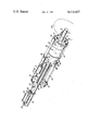
An embodiment of the present invention will now be described solely by way of example and with reference to the accompanying drawing which is a generally schematic perspective view of pipe cleaning apparatus.
Referring now to the drawing, the pipe cleaning apparatus comprises a cleaning tool motor 1 having an outer casing or housing 16 from one end 17 of which a drive shaft 2 of circular cross section projects. The drive shaft 2 is normally fitted at one end remote from the motor 1, with any suitable connecting means such for example as a crows foot coupling (not shown), by means of which a cleaning tool (shown schematically as cleaning tool 2a) may be securely fitted at the end of the drive shaft 2 remote from the motor 1. The cleaning tool 2a may take any conventional form and will be selected in accordance with the type of cleaning job to be carried out. Thus, for example, the cleaning tool may have cutting teeth, arms with cutters, chains or metal block knocking heads. Spaced around the end 17 of the housing 16 are three guide devices in the form of guide wheels 3. The guide wheels 3 are disposed radially with respect to the drive shaft 2 so as to bear against the walls of a pipe to be cleaned. The guide wheels 3 are mounted on spindles 13. The spindles 13 are journaled for rotation in and supported by arms 14. The arms 14 form part of mechanical linkages 4 which are hinged at an end 18 of the housing 16 in hinge lugs 15 secured to the housing 16. To enable the pipe cleaning apparatus to be used with various sizes of pipe, the guide wheels 3 are manually jacked outwardly or inwardly by means of screw threaded members (not shown) extending from the guide wheel 3 and arm 14 ends of the mechanical linkages 4 to the housing 16 of the motor 1. When the guide wheels 3 are in the correct position, the screw threaded members are locked in position.
Arranged adjacent the end 18 of the motor housing, are three jacking arms 5. The jacking arms 5 are equally spaced apart and the drive wheels 6 are mounted on the jacking arms 5. The drive wheels 6 are disposed radially so as to engage in driving connection with the inside surface of a pipe to be cleaned. Each drive wheel 6 has operatively associated with it, its own pneumatic motor 7. Each pneumatic motor 7 drives its drive wheel 6 through a rotatable shaft 19 and a crown wheel and piston (not shown). In the drawing, only one pneumatic motor 7 is shown for simplicity of illustration. The pneumatic motors 7 are fed with compressed air via pipes 8 to provide driving force for the drive wheels 6, whereby the pipe cleaning apparatus can be driven through the pipe to be cleaned. Compressed air for the cleaning tool motor 1 is provided by a coaxially arranged feedpipe 9 which extends along the longitudinal axis of the pipe cleaning apparatus.
In order to bring the drive wheels 6 into intimate driving contact with the inside surface of a pipe to be cleaned, the uppermost of the jacking arms 5 as shown in the drawing, is coupled through a mechanical linkage 10 to a pneumatically controlled jacking arm actuator means which takes the form of an air jack 11. The air jack 11 has an output piston shaft 12 connected to drive the jacking arm 5 via the mechanical linkage 10, radially inwardly and outwardly as desired. The other two jacking arms 5 are manually jacked inwardly or outwardly to the approximate inside diameter of the pipe to be cleaned and they are then fixed in position. The uppermost jacking arm 5 can then be raised as desired, to cause the pipe cleaning apparatus to sit coaxially in the pipe so that all of the drive wheels 6 engage with the inside surface of the pipe to be cleaned. The uppermost jacking arm 5 is lowered in order to disengage the drive wheels 6 from the inside surface of the pipe, thus enabling the pipe cleaning apparatus easily to be removed from the cleaned pipe.
Thus in operation, after the pipe cleaning apparatus has been loaded into a pipe to be cleaned, compressed air is supplied to the pipes 8, the pipe 9 and a pipe 20 which feeds the air jack 11. The pipes 8, 9, 20 are fed via control valves (not shown) so that the drive shaft 2, the drive wheels 6 and the uppermost jacking arm 5 can be operated independently if desired. Having introduced the pipe cleaning apparatus into a pipe to be cleaned, the cleaning motor 1 is energised so that the cleaning tool 2a attached to the shaft 2 rotates and proceeds to clean the inside surface of the pipe. Whilst this operation is in progress, the air motors 7 are energised so that the drive wheels 6 rotate to drive the pipe cleaning apparatus at a uniform speed along the pipe whereby the whole length of the pipe is cleaned progressively. Whilst the cleaning procedure is in progress and the pipe cleaning apparatus is being driven along the pipe, the drive wheels 6 are maintained in driving contact with the inside surface of the pipe by the air jack 11 which operates through the mechanical linkages 10 to force the uppermost of the drive wheels 6 into driving contact with the pipe. The other two drive wheels 6 are thereby automatically centralised so as to make the required driving contact as described above.
It will be readily appreciated that the size of the pipe cleaning apparatus is determined by the size of the pipe to be cleaned and that a wide variation in pipe sizes is possible.
By utilising pipe cleaning apparatus as hereinbefore decribed, the tedious manual procedure hitherto utilised is avoided and efficient quick pipe cleaning is facilitated. The pipe cleaning apparatus can proceed along the pipe at a steady speed whereas with manual cleaning, the cleaning speed is often erratic due to the fact that rigid cleaning rods are being pushed through the pipes by hand.
Control of the pipe cleaning apparatus is advantageously effected from a control console remote from the pipe cleaning apparatus. The control console may have a control valve for the air jack 11, a pressure regulator for controlling the air pressure for the air jack 11, a control valve for the cleaning tool 2a, and a control valve which is connected to all three motors 7 and which is a directional valve used for controlling the direction of operation of the motors 7 depending upon whether the pipe cleaning apparatus is required to go into or be withdrawn from a pipe. The control valve for the three motors 7 also has an OFF position for turning the motors 7 off. There is also a pressure regulator for the control valve for the three motors 7, by means of which the power developed by the motors 7 can be controlled.
Claims (10)
1. Apparatus for cleaning the bore of a pipe comprising: a housing means, a cleaning tool motor mounted in said housing means with its drive shaft extending from the housing means and adapted to receive a pipe cleaning tool rotatable with the drive shaft, at least three guide devices, support means connected to the housing means and supporting said guide devices and disposed around the housing means in spaced apart relationship towards the drive shaft end of the housing so as in use to bear against the bore of a pipe to be cleaned thereby to position the drive shaft coaxially of the pipe, drive wheel means for advancing said housing means through a pipe, means for mounting said drive wheel means on said housing means, drive motor means operatively associated with the drive wheel means for driving the apparatus through a pipe to be cleaned, a jacking means for the drive wheel means which extends away from the end of the housing means remote from the drive shaft, and actuator means operative for actuating said jacking means for jacking the drive wheel means into driving contact with the wall of a pipe to be cleaned.
2. Apparatus as claimed in claim 1 wherein the cleaning tool motor, the drive motor means and the actuator means are arranged to be operated pneumatically by compressed air fed to the apparatus via feedpipe means.
3. Apparatus as claimed in claim 2 wherein the feedpipe means comprises a main feedpipe which extends along the longitudinal axis of the apparatus so as to feed the cleaning tool motor.
4. Apparatus as claimed in claim 1, claim 2, or claim 3 wherein the guide devices are guide wheels.
5. Apparatus as claimed in claim 1 wherein the drive wheel means comprises three drive wheels.
6. Apparatus as claimed in claim 5 wherein the drive motor means comprises separate air motors, one for each drive wheel.
7. Apparatus as claimed in claim 5 wherein the jacking means is a controllable jacking arm for one of the drive wheels, the remaining drive wheels being mounted on manually adjustable arms.
8. Apparatus as claimed in claim 7 wherein the controllable jacking arm is operatively coupled to actuator means formed by a pneumatically controlled actuator, the pneumatically controlled actuator being fed from a feed pipe means.
9. Apparatus as claimed in claim 8 wherein the pneumatically controlled actuator comprises a cylinder within which a drive piston is enclosed and arranged so as to drive through mechanical linkages the jacking arm, responsively to the application of compressed air to the cylinder which is fed thereto via the feed pipe means.
10. Apparatus as claimed in claim 9 wherein the pneumatically controlled actuator is a double action actuator which is drivable in reverse so as to move the jacking arm inwardly.
Applications Claiming Priority (2)
| Application Number | Priority Date | Filing Date | Title |
|---|---|---|---|
| GB8107823 | 1981-03-12 | ||
| GB8107823 | 1981-03-12 |
Publications (1)
| Publication Number | Publication Date |
|---|---|
| US4418437A true US4418437A (en) | 1983-12-06 |
Family
ID=10520345
Family Applications (1)
| Application Number | Title | Priority Date | Filing Date |
|---|---|---|---|
| US06/355,192 Expired - Fee Related US4418437A (en) | 1981-03-12 | 1982-03-05 | Pipe cleaning apparatus |
Country Status (5)
| Country | Link |
|---|---|
| US (1) | US4418437A (en) |
| CA (1) | CA1178005A (en) |
| IT (1) | IT1150614B (en) |
| NL (1) | NL8200997A (en) |
| NO (1) | NO153040C (en) |
Cited By (20)
| Publication number | Priority date | Publication date | Assignee | Title |
|---|---|---|---|---|
| US4520524A (en) * | 1984-03-26 | 1985-06-04 | Long Jr Charles A | Remotely controlled hydraulic cleaner apparatus |
| US4662023A (en) * | 1985-05-08 | 1987-05-05 | Westinghouse Electric Corp. | Ice removal auger for ice condenser containment |
| JPS6340028A (en) * | 1986-08-05 | 1988-02-20 | 住吉重工業株式会社 | Suction discharge apparatus of deposit in sewage |
| US4763376A (en) * | 1986-05-27 | 1988-08-16 | Pene-Tech, Inc. | Maintenance inspection submersible transport apparatus |
| GB2214263A (en) * | 1988-01-26 | 1989-08-31 | Kubota Ltd | Pipe pig |
| US5020188A (en) * | 1989-08-04 | 1991-06-04 | J. F. Walton & Co., Inc. | Duct cleaning apparatus |
| US5072487A (en) * | 1989-08-04 | 1991-12-17 | J. F. Walton & Co., Inc. | Duct cleaning apparatus |
| US5122193A (en) * | 1990-08-10 | 1992-06-16 | Albuquerque Underground, Inc. | Pipe cleaning modules and systems and methods for their use |
| US5226207A (en) * | 1991-12-20 | 1993-07-13 | William Elzaurdia | Sewer unclogger |
| US5233791A (en) * | 1992-03-02 | 1993-08-10 | Mcqueen Jr Joe C | Apparatus for grinding the internal surface of pipe |
| US5377381A (en) * | 1992-10-26 | 1995-01-03 | Wilson; Edward G. | Cleaning system and method |
| US5435854A (en) * | 1990-08-10 | 1995-07-25 | Pipeline Sewer Services, Inc. | Pipe cleaning modules and systems and methods for their use |
| GB2287767A (en) * | 1994-03-15 | 1995-09-27 | Peter Gilboy | Apparatus for cleaning the interiors of pipes |
| US20100139019A1 (en) * | 2007-04-27 | 2010-06-10 | Christian Geppert | Cleaning Apparatus for Large Diameter Pipe |
| US20110017233A1 (en) * | 2008-03-14 | 2011-01-27 | Diversey, Inc. | Cleaning bullet and method of operating the same |
| CN103968188A (en) * | 2014-04-19 | 2014-08-06 | 浙江中博信息工程有限公司 | Air conditioner pipeline detecting and cleaning system |
| US20150017061A1 (en) * | 2013-07-15 | 2015-01-15 | American Water Works Company, Inc. | Disinfection of water mains using ultraviolet light |
| US8973738B2 (en) | 2011-03-28 | 2015-03-10 | Diversey, Inc. | Cleaning device |
| US11142470B2 (en) | 2013-07-15 | 2021-10-12 | American Water Works Company, Inc. | Disinfection of water mains using ultraviolet light and oxidizing agents |
| CN114029293A (en) * | 2021-10-27 | 2022-02-11 | 华能武汉发电有限责任公司 | Pipeline axial displacement device and cleaning device thereof |
Families Citing this family (1)
| Publication number | Priority date | Publication date | Assignee | Title |
|---|---|---|---|---|
| US4773115A (en) * | 1985-10-08 | 1988-09-27 | Systems Canada Limited | Sewer cleaning device |
Citations (4)
| Publication number | Priority date | Publication date | Assignee | Title |
|---|---|---|---|---|
| US2604521A (en) * | 1948-06-09 | 1952-07-22 | Cormack E Boucher | Conduit tractor |
| US3078823A (en) * | 1960-01-18 | 1963-02-26 | Crutcher Rolfs Cummings Inc | Internal pipe coating apparatus |
| US3099227A (en) * | 1960-08-05 | 1963-07-30 | Harvest Queen Mill & Elevator | Pipeline vehicle governing device |
| US4369713A (en) * | 1980-10-20 | 1983-01-25 | Transcanada Pipelines Ltd. | Pipeline crawler |
-
1982
- 1982-03-04 IT IT19976/82A patent/IT1150614B/en active
- 1982-03-04 CA CA000397575A patent/CA1178005A/en not_active Expired
- 1982-03-05 US US06/355,192 patent/US4418437A/en not_active Expired - Fee Related
- 1982-03-10 NL NL8200997A patent/NL8200997A/en not_active Application Discontinuation
- 1982-03-11 NO NO820792A patent/NO153040C/en unknown
Patent Citations (4)
| Publication number | Priority date | Publication date | Assignee | Title |
|---|---|---|---|---|
| US2604521A (en) * | 1948-06-09 | 1952-07-22 | Cormack E Boucher | Conduit tractor |
| US3078823A (en) * | 1960-01-18 | 1963-02-26 | Crutcher Rolfs Cummings Inc | Internal pipe coating apparatus |
| US3099227A (en) * | 1960-08-05 | 1963-07-30 | Harvest Queen Mill & Elevator | Pipeline vehicle governing device |
| US4369713A (en) * | 1980-10-20 | 1983-01-25 | Transcanada Pipelines Ltd. | Pipeline crawler |
Cited By (28)
| Publication number | Priority date | Publication date | Assignee | Title |
|---|---|---|---|---|
| US4520524A (en) * | 1984-03-26 | 1985-06-04 | Long Jr Charles A | Remotely controlled hydraulic cleaner apparatus |
| US4662023A (en) * | 1985-05-08 | 1987-05-05 | Westinghouse Electric Corp. | Ice removal auger for ice condenser containment |
| US4763376A (en) * | 1986-05-27 | 1988-08-16 | Pene-Tech, Inc. | Maintenance inspection submersible transport apparatus |
| JPS6340028A (en) * | 1986-08-05 | 1988-02-20 | 住吉重工業株式会社 | Suction discharge apparatus of deposit in sewage |
| GB2214263B (en) * | 1988-01-26 | 1992-03-11 | Kubota Ltd | Self-propelled vehicle for use in pipes |
| US4938167A (en) * | 1988-01-26 | 1990-07-03 | Kubota Ltd. | Self-propelled vehicle for use in pipes |
| GB2214263A (en) * | 1988-01-26 | 1989-08-31 | Kubota Ltd | Pipe pig |
| US5020188A (en) * | 1989-08-04 | 1991-06-04 | J. F. Walton & Co., Inc. | Duct cleaning apparatus |
| US5072487A (en) * | 1989-08-04 | 1991-12-17 | J. F. Walton & Co., Inc. | Duct cleaning apparatus |
| US5622571A (en) * | 1990-08-10 | 1997-04-22 | Pipeline Services, Inc. | Pipe cleaning modules and systems and methods for their use |
| US5122193A (en) * | 1990-08-10 | 1992-06-16 | Albuquerque Underground, Inc. | Pipe cleaning modules and systems and methods for their use |
| US5435854A (en) * | 1990-08-10 | 1995-07-25 | Pipeline Sewer Services, Inc. | Pipe cleaning modules and systems and methods for their use |
| US5226207A (en) * | 1991-12-20 | 1993-07-13 | William Elzaurdia | Sewer unclogger |
| US5233791A (en) * | 1992-03-02 | 1993-08-10 | Mcqueen Jr Joe C | Apparatus for grinding the internal surface of pipe |
| US5460563A (en) * | 1992-03-02 | 1995-10-24 | Mcqueen, Jr.; Joe C. | Method for preparing the internal surface of pipe |
| US5377381A (en) * | 1992-10-26 | 1995-01-03 | Wilson; Edward G. | Cleaning system and method |
| GB2287767A (en) * | 1994-03-15 | 1995-09-27 | Peter Gilboy | Apparatus for cleaning the interiors of pipes |
| GB2287767B (en) * | 1994-03-15 | 1998-08-12 | Peter Gilboy | Pipe cleaning |
| US20100139019A1 (en) * | 2007-04-27 | 2010-06-10 | Christian Geppert | Cleaning Apparatus for Large Diameter Pipe |
| US20110017233A1 (en) * | 2008-03-14 | 2011-01-27 | Diversey, Inc. | Cleaning bullet and method of operating the same |
| US8454753B2 (en) * | 2008-03-14 | 2013-06-04 | Diversey, Inc. | Cleaning bullet and method of operating the same |
| US8732894B2 (en) | 2008-03-14 | 2014-05-27 | Diversey, Inc. | Cleaning bullet and method of operating the same |
| US8973738B2 (en) | 2011-03-28 | 2015-03-10 | Diversey, Inc. | Cleaning device |
| US20150017061A1 (en) * | 2013-07-15 | 2015-01-15 | American Water Works Company, Inc. | Disinfection of water mains using ultraviolet light |
| US9586837B2 (en) * | 2013-07-15 | 2017-03-07 | American Water Works Company, Inc. | Disinfection of water mains using ultraviolet light |
| US11142470B2 (en) | 2013-07-15 | 2021-10-12 | American Water Works Company, Inc. | Disinfection of water mains using ultraviolet light and oxidizing agents |
| CN103968188A (en) * | 2014-04-19 | 2014-08-06 | 浙江中博信息工程有限公司 | Air conditioner pipeline detecting and cleaning system |
| CN114029293A (en) * | 2021-10-27 | 2022-02-11 | 华能武汉发电有限责任公司 | Pipeline axial displacement device and cleaning device thereof |
Also Published As
| Publication number | Publication date |
|---|---|
| IT8219976A0 (en) | 1982-03-04 |
| NL8200997A (en) | 1982-10-01 |
| NO153040B (en) | 1985-09-30 |
| NO820792L (en) | 1982-09-13 |
| NO153040C (en) | 1986-01-08 |
| CA1178005A (en) | 1984-11-20 |
| IT1150614B (en) | 1986-12-17 |
Similar Documents
| Publication | Publication Date | Title |
|---|---|---|
| US4418437A (en) | Pipe cleaning apparatus | |
| US4411178A (en) | Pipe end preparation machine | |
| KR920008803B1 (en) | Telescoping parts manipulator | |
| US10556271B2 (en) | Pipe end truing apparatus and method | |
| EP0029343A2 (en) | Lining cutter and cutting method | |
| HUT67874A (en) | Method and device for treatment of interior of non-accessible pipelines | |
| US4620823A (en) | Portable tube milling tool | |
| US4509236A (en) | Boring machines | |
| EP0397448B1 (en) | Device for working inside of pipes | |
| GB2094926A (en) | Pipe cleaning apparatus | |
| HU206766B (en) | Renovating machine for repairing and sealing impassable pipings | |
| GB2113126A (en) | Remotely controlled internal pipeline cutting apparatus | |
| CN1085836A (en) | Pipe cutting machine | |
| EP0029342A1 (en) | Remote inspection equipment | |
| WO1999022895A1 (en) | Apparatus and method for counterboring a pipe | |
| US5433130A (en) | Shoulder dressing apparatus | |
| US4520524A (en) | Remotely controlled hydraulic cleaner apparatus | |
| SU854610A1 (en) | Apparatus for working tube from inner side | |
| US3216295A (en) | Internal pipe cutter | |
| CN215165869U (en) | Device for replacing road manhole cover seat | |
| US20020017505A1 (en) | Apparatus for welding | |
| JP2868733B2 (en) | Pipe cutting method and cutting device | |
| US4128207A (en) | Fluid delivery system | |
| JPS5862218A (en) | Method and apparatus for cutting steel tubular sheet pile | |
| AU779791B2 (en) | Apparatus for welding |
Legal Events
| Date | Code | Title | Description |
|---|---|---|---|
| FEPP | Fee payment procedure |
Free format text: MAINTENANCE FEE REMINDER MAILED (ORIGINAL EVENT CODE: REM.); ENTITY STATUS OF PATENT OWNER: SMALL ENTITY |
|
| LAPS | Lapse for failure to pay maintenance fees | ||
| STCH | Information on status: patent discontinuation |
Free format text: PATENT EXPIRED DUE TO NONPAYMENT OF MAINTENANCE FEES UNDER 37 CFR 1.362 |
|
| FP | Lapsed due to failure to pay maintenance fee |
Effective date: 19871206 |