US4416398A - Variable spray overcap aerosol assembly - Google Patents
Variable spray overcap aerosol assembly Download PDFInfo
- Publication number
- US4416398A US4416398A US06/347,887 US34788782A US4416398A US 4416398 A US4416398 A US 4416398A US 34788782 A US34788782 A US 34788782A US 4416398 A US4416398 A US 4416398A
- Authority
- US
- United States
- Prior art keywords
- valve
- actuator
- finger
- symmetrical
- actuator button
- Prior art date
- Legal status (The legal status is an assumption and is not a legal conclusion. Google has not performed a legal analysis and makes no representation as to the accuracy of the status listed.)
- Expired - Fee Related
Links
Images


Classifications
-
- B—PERFORMING OPERATIONS; TRANSPORTING
- B65—CONVEYING; PACKING; STORING; HANDLING THIN OR FILAMENTARY MATERIAL
- B65D—CONTAINERS FOR STORAGE OR TRANSPORT OF ARTICLES OR MATERIALS, e.g. BAGS, BARRELS, BOTTLES, BOXES, CANS, CARTONS, CRATES, DRUMS, JARS, TANKS, HOPPERS, FORWARDING CONTAINERS; ACCESSORIES, CLOSURES, OR FITTINGS THEREFOR; PACKAGING ELEMENTS; PACKAGES
- B65D83/00—Containers or packages with special means for dispensing contents
- B65D83/14—Containers or packages with special means for dispensing contents for delivery of liquid or semi-liquid contents by internal gaseous pressure, i.e. aerosol containers comprising propellant for a product delivered by a propellant
- B65D83/16—Containers or packages with special means for dispensing contents for delivery of liquid or semi-liquid contents by internal gaseous pressure, i.e. aerosol containers comprising propellant for a product delivered by a propellant characterised by the actuating means
- B65D83/20—Containers or packages with special means for dispensing contents for delivery of liquid or semi-liquid contents by internal gaseous pressure, i.e. aerosol containers comprising propellant for a product delivered by a propellant characterised by the actuating means operated by manual action, e.g. button-type actuator or actuator caps
- B65D83/205—Actuator caps, or peripheral actuator skirts, attachable to the aerosol container
- B65D83/206—Actuator caps, or peripheral actuator skirts, attachable to the aerosol container comprising a cantilevered actuator element, e.g. a lever pivoting about a living hinge
-
- B—PERFORMING OPERATIONS; TRANSPORTING
- B65—CONVEYING; PACKING; STORING; HANDLING THIN OR FILAMENTARY MATERIAL
- B65D—CONTAINERS FOR STORAGE OR TRANSPORT OF ARTICLES OR MATERIALS, e.g. BAGS, BARRELS, BOTTLES, BOXES, CANS, CARTONS, CRATES, DRUMS, JARS, TANKS, HOPPERS, FORWARDING CONTAINERS; ACCESSORIES, CLOSURES, OR FITTINGS THEREFOR; PACKAGING ELEMENTS; PACKAGES
- B65D83/00—Containers or packages with special means for dispensing contents
- B65D83/14—Containers or packages with special means for dispensing contents for delivery of liquid or semi-liquid contents by internal gaseous pressure, i.e. aerosol containers comprising propellant for a product delivered by a propellant
- B65D83/16—Containers or packages with special means for dispensing contents for delivery of liquid or semi-liquid contents by internal gaseous pressure, i.e. aerosol containers comprising propellant for a product delivered by a propellant characterised by the actuating means
- B65D83/22—Containers or packages with special means for dispensing contents for delivery of liquid or semi-liquid contents by internal gaseous pressure, i.e. aerosol containers comprising propellant for a product delivered by a propellant characterised by the actuating means with a mechanical means to disable actuation
-
- B—PERFORMING OPERATIONS; TRANSPORTING
- B65—CONVEYING; PACKING; STORING; HANDLING THIN OR FILAMENTARY MATERIAL
- B65D—CONTAINERS FOR STORAGE OR TRANSPORT OF ARTICLES OR MATERIALS, e.g. BAGS, BARRELS, BOTTLES, BOXES, CANS, CARTONS, CRATES, DRUMS, JARS, TANKS, HOPPERS, FORWARDING CONTAINERS; ACCESSORIES, CLOSURES, OR FITTINGS THEREFOR; PACKAGING ELEMENTS; PACKAGES
- B65D83/00—Containers or packages with special means for dispensing contents
- B65D83/14—Containers or packages with special means for dispensing contents for delivery of liquid or semi-liquid contents by internal gaseous pressure, i.e. aerosol containers comprising propellant for a product delivered by a propellant
- B65D83/44—Valves specially adapted therefor; Regulating devices
- B65D83/46—Tilt valves
Definitions
- This invention relates to aerosol products and containers and more particularly to a plural spray rate overcap assembly.
- the assembly of the parts for a plural spray rate aerosol container requires a preferred orientation of the parts during the assembly process. Accordingly, it is more costly to assemble a plural spray rate assembly since the parts must be located in a preferred orientation to properly complete the assembly.
- Another object of this invention is to provide a plural spray rate assembly for use with an aerosol container which may be assembled with the same number of component parts as a conventional aerosol container.
- Another object of this invention is to provide a plural spray rate assembly for an aerosol container wherein the component parts may be assembled without concern for the orientation of the component parts.
- Another object of this invention is to provide a plural spray rate assembly for an aerosol container utilizing an aerosol overcap having a finger actuator wherein the overcap is rotatably mounted on the container relative to an actuator button for enabling and first and a second spray upon a first and second selected orientation between the overcap and the actuator button.
- Another object of this invention is to provide a plural spray rate assembly for an aerosol container comprising a non-symmetrical means cooperable with an aperture whereby the vertical depression and tilting of the valve may be actuated by the operator upon a selected orientation between the non-symmetrical means and the aperture.
- Another object of this invention is to provide a plural spray rate assembly for aerosol containers for use with standard industry aerosol containers and valves.
- the invention may be incorporated into a plural spray rate aerosol assembly for use with an aerosol container having a valve for discharging aerosol product at a first rate upon a vertical depression of the valve and for discharging aerosol product at a second rate upon tilting the valve.
- the invention comprises an actuator button having a terminal orifice.
- a valve stem connects the actuator button with the valve for discharging the aerosol product through the terminal orifice upon movement of the valve.
- An overcap is rotatably mounted relative to the aerosol container for at least partially covering the actuator button.
- a finger actuator is movably mounted relative to the overcap.
- Means such as non-symmetric means, is established between the finger actuator and the actuator button for vertically depressing the valve upon operator movement of the finger actuator when the overcap is disposed in a first rotational position relative to the actuator button and for tilting the valve upon operator movement of the finger actuator when the overcap is disposed in a second rotational position relative to the actuator button.
- a non-symmetrical aperture is disposed on one of the actuator buttons and the finger actuator for cooperation with a non-symmetrical means in the other of the actuator button and finger actuator.
- the non-symmetrical means is prevented from entering the non-symmetrical aperture for transferring the finger movement of the operator to vertically depress the valve upon a first selected orientation of the finger actuator relative to the actuator button.
- the non-symmetrical means enters the non-symmetrical aperture to transfer the finger movement of the operator to tilt the valve upon a second selected orientation of the finger actuator relative to the actuator button.
- the finger actuator is pivotably mounted to the overcap with the pivot axis being displaced from the axis of the valve for moving the valve when the non-symmetrical means enters the aperture.
- the aperture may be a non-symmetrical aperture with the same distinctive shape as the non-symmetrical means enabling the non-symmetrical means to enter in only a limited number of orientations of the finger actuator relative to the actuator button.
- the finger actuator may be an integral member with the overcap wherein the finger actuator is pivotably mounted relative to the overcap through an integral hinge.
- the plural spray rate assembly is suitable for use with both a vertical and a horizontal aerosol overcap.
- the terminal orifice of the actuator button extends at least partially through the non-symmetrical aperture for discharging aerosol product through the non-symmetrical aperture.
- the non-symmetrical aperture may be disposed in the finger actuator and the non-symmetrical means may comprise the outer configuration of the actuator button.
- the overcap comprises a sidewall orifice disposed in a sidewall of the overcap with the terminal orifice of the actuator button disposed adjacent to the sidewall orifice for discharging aerosol product through the sidewall orifice in a direction substantially perpendicular to the axis of the aerosol container.
- the non-symmetrical means comprises a projection disposed on the finger actuator. It should be understood that the non-symmetrical means and the aperture may be interchanged within the structure in either the vertical or horizontal overcap.
- FIG. 1 is a rear elevational view of a plural spray rate aerosol assembly
- FIG. 2 is an enlarged side sectional view of a valve for use with the overcap of the assembly shown in FIG. 1 in the unattended position;
- FIG. 3 is a side sectional view of the valve of FIG. 2 in the vertically depressed position
- FIG. 3A is a bottom view of the valve stem of FIG. 2;
- FIG. 4 is a side sectional view of the valve of FIG. 2 in the tilted position
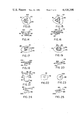
- FIG. 5 is a plan view of a first embodiment of the assembly shown in a first selected orientation
- FIG. 6 is a side sectional view of FIG. 5;
- FIG. 7 is a plan view of the assembly shown in FIG. 4 with the overcap shown in a second selected orientation
- FIG. 8 is a side sectional view of FIG. 7;
- FIG. 9 is a plan view of a second embodiment of the assembly shown in a first selected orientation
- FIG. 9A is an enlarged partial side view of FIG. 9;
- FIG. 10 is a plan view of the second embodiment shown in FIG. 9 in the second selected orientation
- FIG. 11 is a plan view of a third embodiment of the assembly shown in the first selected orientation
- FIG. 12 is a plan view of the third embodiment shown in FIG. 11 in the selected orientation
- FIG. 13 is a plan view of a fourth embodiment showing the overcap in a first selected orientation
- FIG. 14 is a side sectional view of FIG. 13;
- FIG. 15 is a plan view of FIG. 13 with the overcap in a second selected orientation
- FIG. 16 is a side sectional view of FIG. 15;
- FIG. 17 is still a fifth embodiment of the invention showing the overcap in a first selected orientation
- FIG. 18 is a side sectional view of FIG. 17;
- FIG. 19 is a plan view of the overcap shown in FIG. 17 in the second selected orientation
- FIG. 20 is a side sectional view of FIG. 19;
- FIG. 21 is a side view of a sixth embodiment of the invention.
- FIG. 22 is a view along line 22--22 in FIG. 21;
- FIG. 23 is a view along line 23--23 in FIG. 21;
- FIG. 24 shows the vertical depression of the actuator button of FIG. 21
- FIG. 25 shows the tilting of the actuator button of FIG. 21
- FIG. 26 is an elevational view of the assembly incorporated into a horizontal overcap
- FIG. 27 is a rear elevational view of FIG. 26;
- FIG. 28 is a side view partially in section of the horizontal overcap assembly shown in FIGS. 26 and 27;
- FIG. 29 is a view along line 29--29 in FIG. 28;
- FIG. 30 is a view along line 30--30 in FIG. 28;
- FIG. 31 is a side view partially in section showing a vertical depression of the valve assembly in the first selected orientation.
- FIG. 32 is a side view partially in section showing a tilting of the valve assembly in the second selected orientation.
- FIG. 1 is a rear perspective view of the plural spray rate aerosol overcap 10 disposed on an aerosol container 12 containing a propellant and a product.
- the overcap 10 is affixed to an upper rim 14 of the aerosol container 12 as shown in FIG. 6.
- the overcap 10 covers an actuator button 15 having a terminal orifice 16 shown in FIGS. 2-4 with a finger actuator 17 disposed adjacent a finger recess 18 in the overcap 10.
- An aperture 20 is disposed in the finger actuator 17 for enabling a vertical spray to be discharged substantially along the axis of symmetry of the aerosol container 12. It will be appreciated from the following description that the invention may be suitable for use with either a vertical overcap as shown in FIG. 1 or a horizontal overcap as shown in FIGS.
- the overcap 10 may be secured to other surfaces of the aerosol container 12 including, but not limited to, the inside or outside rim of the container 12 or the inside or outside rim of the mounting cup or other means.
- FIGS. 2-4 illustrate a valve assembly which is suitable for use with the invention set forth herein.
- the valve assembly is generally indicated as a tilt and vertical action valve and includes a valve body 22 having a body cavity 24 formed on the interior thereof.
- a tail portion 26 is integrally attached or otherwise connected to the valve body 22 and is attached to a dip tube 30.
- the dip tube 30 is disposed in fluid communication between the interior of the aerosol container 12 and the body cavity 24.
- the valve body 22 is mounted to a conventional mounting cup 32 with a sealing gasket 34 disposed in sealing engagement about the upper periphery 36 of the valve body 22.
- a valve stem 38 having a flat base portion 40 extends through a gasket aperture 39 to allow relatively free movement of the base 40 of the valve stem 38 as will be explained in greater detail hereinafter.
- the stem 38 has a through aperture 42 extending between the substantially flat base 40 and the actuator button 15.
- the present invention is compatible with either a one-piece button and valve stem assembly or a distinct actuator button, as shown.
- a valve stem sealer 46 is disposed within the body cavity 24 with the upper periphery 48 of the valve stem sealer being biased by spring 50 to form a first seal with the sealing gasket 34.
- the substantially flat base portion 40 of the valve stem is supported on a substantially flat platform 52 of the valve stem sealer 46.
- a first metering orifice 47A shown as a slot 47A in FIG. 3A is disposed within the stem base 40 whereas a second metering orifice 47B is disposed in the stem aperture 42.
- This valve configuration has been disclosed in U.S. Pat. Nos. 3,506,241 and 4,243,161 which are hereby incorporated by reference.
- the first and second metering apertures 47A and 47B are selected to be of different sizes to provide a first and a second flow rate as will become apparent hereinafter.
- FIG. 3 illustrates a vertical depression of the valve stem 38 to disengage the upper periphery 48 of the valve stem sealer 46 from the gasket 34 to enable the product and propellant to flow around the upper periphery 48 of the valve stem sealer 46 and through the first metering orifice 47A to provide a first flow rate through stem aperture 42.
- FIG. 4 illustrates the tilting of the valve stem 38 to disengage the upper periphery 48 of the valve stem sealer 46 from the sealing gasket 34 while the flat base 40 disengages with the flat platform 52.
- the product and propellant flows from dip tube 30 around the upper periphery 48 of the valve stem sealer 46 and through the second metering orifice 47B to provide a second flow rate through stem aperture 42.
- FIG. 5 is a plan view of the assembly with a side sectional view being fully shown in FIG. 6.
- the finger actuator 17 is pivotally mounted by a pivot 54 to the overcap 10 which overcap is rotatably mounted on the rim 14 relative to the aerosol container 12.
- the finger actuator 17 is mounted by a hinge 54 with the pivot axis being displaced from the axis of the valve extending through stem 38 to generate a tilting motion to the valve button 15.
- the finger actuator 17 is an integral one-piece member with the overcap 10.
- an important aspect of the present invention resides in an aperture disposed in either the actuator button or the finger actuator for cooperation with a non-symmetrical means in the other of the actuator button or the finger actuator.
- the aperture 20 is disposed in the finger actuator 17 and the non-symmetrical means comprises the actuator button 15.
- the term "non-symmetrical means" refers to a non-symmetry relative to an axis extending through the valve stem 38.
- the actuator button 15 has the shape of an arrowhead with the aperture 20 also being a non-symmetrical aperture having an identical shape but being slightly larger than the outer configuration of the actuator button 15.
- the distinctively shaped non-symmetrical aperture 20 is slightly larger than the distinctively shaped non-symmetrical means of the actuator button 15 enabling the actuator button 15 to enter the aperture 20 at a skewed angle in only a limited number of selected orientations.
- FIG. 5 illustrates a first selected orientation between the button 15 and the overcap 10 wherein the aperture 20 will not receive the non-symmetrical actuator button 15.
- FIG. 6 illustrates the result of depressing the finger actuator 17 when the actuator button 15 and the finger actuator 17 are in the first selected orientation as shown in FIG. 5.
- the finger actuator 17 immediately contacts the upper surface of the non-symmetrical button 15 to vertically depress the valve stem 38.
- the product and propellant are discharged at a first rate from the aerosol container 12 as determined by the first metering orifice 47A.
- FIG. 7 illustrates a plan view of the assembly shown in FIGS. 5 and 6 in the second selected orientation of the finger actuator 17 relative to the actuator button 15. It is evident that the overcap 10 has been rotated 180 degrees relative to the container 12 to align the non-symmetrical actuator button 15 and the non-symmetrical aperture 20.
- FIG. 8 illustrates the result of depressing of the finger actuator 17 with the second selected orientation as shown in FIG. 7.
- the non-symmetrical button 15 at least partially enters the non-symmetrical aperture 20 whereby a sidewall of the aperture engages the button 15 to tilt the valve stem 38 and discharge product and propellant from the terminal orifice 16 and through the aperture 20 in accordance with the second metering orifice 47B.
- the invention resides in part in the unique tilt valve in combination with a non-symmetrical means and a non-symmetrical aperture disposed on either the finger actuator or the actuator button. This combination enables plural discharge of product and propellant from the container depending on the selected or desired orientation between the overcap and the actuator button.
- FIGS. 9 and 10 show a second embodiment of the assembly in the first selected and a second selected orientation, respectively.
- the aperture 20A is an oval with the non-symmetrical means being a projection 56 extending from the actuator button 15A substantially perpendicular to the axis of the valve stem 38.
- FIGS. 9 and 9A show the first selected orientation wherein the projection 56 strikes the underside of the finger actuator 17A upon depression thereof as shown in FIG. 9 to vertically depress the actuator button 15.
- the actuator button 15A including the projection 56 is received within the non-symmetrical aperture 20A to enable the side of aperture 20A to engage a side of the actuator button 15A to tilt the valve in a manner similar to that shown in FIG. 8.
- the embodiments in FIGS. 5-10 have a single selected orientation between the actuator button and the finger actuator.
- FIGS. 11 and 12 show a third embodiment of the assembly in the first selected and second selected orientation, respectively.
- the actuator button 15B has at least one projection for cooperation with a groove.
- a plurality of projections 58 extend substantially perpendicular to the axis of the valve stem 38.
- the non-symmetrical aperture 20B includes three radially spaced grooves 60 for receiving the projections upon the second selected orientation.
- the interrelation between the actuator button and finger actuator is identical to that heretofore described except that three selected second angular orientations exist between the overcap 10B and the actuator button 15B. It should be understood that a non-equiangular relationship may exist between the projection 58 producing a single second selected angular orientation.
- FIG. 13 illustrates a fourth embodiment of the invention wherein a finger actuator 17C has a substantially triangular shaped non-symmetrical aperture 20C disposed above a substantially triangular shaped actuator button 15C.
- FIG. 14 is a side sectional view of FIG. 13 showing aperture 20C comprising sidewalls 62 extending downwardly from the finger actuator 17C.
- the substantially triangularly shaped actuator button 15C may be an isosceles or an equilateral triangle. Other variations such as stars, crosses and the like may be utilized in the practice of this invention.
- FIGS. 15 and 16 show plan and side sectional views of the assemblies shown in FIGS. 13 and 14 in the second selected orientation.
- the triangular shaped button 15C is oriented relative to aperture 20C such that the button 15C is partially received in aperture 20C as shown in FIG. 16. It can be appreciated that actuator button 15C is not received completely through the aperture 20C but is activated by the sidewalls 62.
- FIGS. 17-20 represent a fifth embodiment of the invention with the first selected orientation being shown in FIGS. 17 and 18 and the second selected orientation being shown in FIGS. 19 and 20.
- the non-symmetrical aperture 20D is substantially D-shaped with the actuator button 15D having a top projection 64 extending upwardly from the actuator button 15D.
- the projection 64 contacts the bottom surface of the finger actuator 17D to vertically depress the valve button 15D.
- top projection 64 is engaged by the sidewall of aperture 20D to tilt the valve stem as heretofore described.
- This embodiment illustrates the non-symmetrical means as being a projection extending upwardly from the valve button.
- FIGS. 21-25 A sixth embodiment of the invention is illustrated in FIGS. 21-25.
- the aperture 20E is disposed in the valve button 15E whereas the non-symmetrical means 66 is shown more fully in FIG. 22 whereas the aperture 20E is shown more fully in FIG. 23.
- FIGS. 21-25 show the utilization of an aperture within the actuator button cooperating with non-symmetrical means in the finger actuator. It should be understood that the concept may be utilized in either the vertical or horizontal overcap.
- FIGS. 26-32 show various views of a horizontal embodiment of the present invention.
- the plural spray rate assembly comprises an overcap 110 affixed to the upper rim 114 of an aerosol container 112.
- the overcap 110 covers an actuator button 115 having a terminal orifice 116 more clearly shown in FIG. 28.
- a finger actuator 117 is located in a finger recess 118 of the overcap 112.
- An aperture 120 is disposed in the finger actuator 117 for receiving a non-symmetrical means, shown as a projection 122, extending from the top of actuator button 115.
- the overcap comprises a front recess 124 having a recess orifice 126 located adjacent the terminal orifice 116 of the actuator button enabling a horizontal spray to be discharged substantially perpendicular to the axis of the aerosol container 112.
- FIG. 28 is a side view partially in section of the container shown in FIGS. 26 and 27 with more specific details of the aperture 120 and the projection 122 shown more clearly in FIGS. 29 and 30.
- the non-symmetrical aperture and the non-symmetrical means take the shape of an arrow, resulting in a single selected orientation therebetween.
- the underside of the finger actuator 117 includes guide surfaces 117A and 117B projecting downwardly therefrom for contact with surfaces 115A and 115B of actuator button 115.
- the guide surfaces 117A and 117B insures that the overcap 110 is not rotated relative to the actuator button 115 such that the terminal orifice 116 is misaligned with the overcap recess orifice 126.
- the guide surfaces 117A and 117B have a greater included angle relative to the angle of surfaces 115A and 115B of actuator button 115 enabling the dual spray function of the invention but insures that the overcap is not rotated such that the terminal orifice 116 is beyond the recess orifice 126. Excessive rotation of the overcap 110 by the consumer will cause one of the surfaces 117A or 117B to rotate the actuator button in accordance with the rotation of the overcap 110.
- FIG. 31 illustrates the depression of the finger actuator 117 when the actuator button is in the first selected orientation. Movement of the finger actuator 117 causes a vertical depression of the actuator button 115 resulting in a first discharge of product and propellant in accordance with the first metering orifice 47A.
- FIG. 32 demonstrates the tilting of the valve stem 138 and the actuator button 115 upon depression of the finger actuator 117 when the valve button 115 is in the second selected orientation relative to the overcap 110. The projection 122 is received in aperture 120 enabling the force of actuator 117 to tilt the valve button 115 to enable fluid flow at a second rate determined by second metering orifice 47B.
- the foregoing has set forth a novel plural spray rate assembly which is adaptable to either a horizontal or a vertical overcap.
- the novel configuration resides in part in the simplicity of operation and the simplicity of the parts required to fabricate the assembly.
- the embodiments shown herein do not require any additional component parts from a conventional aerosol overcap assembly.
- the invention does not require any orientation of the valve button relative to the overcap assembly. Since the insertion of the valve button and the overcap assembly is generally accomplished at separate places during assembly, the lack of required orientation is extremely desirable to the aerosol industry.
Abstract
Description
Claims (18)
Priority Applications (1)
| Application Number | Priority Date | Filing Date | Title |
|---|---|---|---|
| US06/347,887 US4416398A (en) | 1980-07-23 | 1982-02-11 | Variable spray overcap aerosol assembly |
Applications Claiming Priority (2)
| Application Number | Priority Date | Filing Date | Title |
|---|---|---|---|
| US06/171,357 US4328911A (en) | 1980-07-23 | 1980-07-23 | Child resistant aerosol actuating overcap |
| US06/347,887 US4416398A (en) | 1980-07-23 | 1982-02-11 | Variable spray overcap aerosol assembly |
Related Parent Applications (1)
| Application Number | Title | Priority Date | Filing Date |
|---|---|---|---|
| US06/171,357 Continuation-In-Part US4328911A (en) | 1980-07-23 | 1980-07-23 | Child resistant aerosol actuating overcap |
Publications (1)
| Publication Number | Publication Date |
|---|---|
| US4416398A true US4416398A (en) | 1983-11-22 |
Family
ID=26867018
Family Applications (1)
| Application Number | Title | Priority Date | Filing Date |
|---|---|---|---|
| US06/347,887 Expired - Fee Related US4416398A (en) | 1980-07-23 | 1982-02-11 | Variable spray overcap aerosol assembly |
Country Status (1)
| Country | Link |
|---|---|
| US (1) | US4416398A (en) |
Cited By (23)
| Publication number | Priority date | Publication date | Assignee | Title |
|---|---|---|---|---|
| US4730752A (en) * | 1986-05-19 | 1988-03-15 | S. C. Johnson & Son Inc. | Anti-seating valve cup |
| GB2211491B (en) * | 1987-12-15 | 1991-12-04 | Sharpliner Limited | Improvement relating to a cap for an aerosol can. |
| WO1993012992A1 (en) * | 1991-12-26 | 1993-07-08 | Abplanalp Robert H | Aerosol actuating cap with side-mounted hinges |
| US5605258A (en) * | 1986-12-03 | 1997-02-25 | Abplanalp; Robert H. | Two-piece aerosol valve for vertical or tilt action |
| US5862960A (en) * | 1997-02-28 | 1999-01-26 | S. C. Johnson & Son, Inc. | Aerosol dispenser |
| US6003739A (en) * | 1998-02-27 | 1999-12-21 | Bartlett; Louie E. | Aerosol spray actuator bar |
| US6296155B1 (en) | 2000-03-09 | 2001-10-02 | Summit Packaging Systems, Inc. | Actuator with compressible internal component |
| US6491187B2 (en) * | 2000-02-02 | 2002-12-10 | Seaquist Perfect Dispensing Foreign, Inc. | Inverted aerosol dispenser |
| US6551001B2 (en) | 2001-09-14 | 2003-04-22 | S. C. Johnson & Son, Inc. | Cleaning device with a trigger-actuated spray canister |
| US20040011824A1 (en) * | 2002-07-22 | 2004-01-22 | Seaquist Perfect Dispensing Foreign, Inc. | Inverted aerosol dispenser |
| EP1400465A1 (en) * | 2002-09-18 | 2004-03-24 | L'oreal | Variable-delivery tiilt valve as well as container having such valve |
| US20040124217A1 (en) * | 2002-09-18 | 2004-07-01 | L'oreal | Variable-flow tilt valve and container fitted with such a valve |
| US6758412B2 (en) | 2001-09-14 | 2004-07-06 | S.C. Johnson & Son, Inc. | Overcap for use with a cleaning device |
| US20040195375A1 (en) * | 2003-01-15 | 2004-10-07 | Richard Koeth | Systems and methods for application of tire treatment agent |
| US20050017026A1 (en) * | 2002-07-22 | 2005-01-27 | Seaquist Perfect Dispensing Foreign, Inc. | Locking aerosol dispenser |
| US20050224518A1 (en) * | 2004-04-13 | 2005-10-13 | Seaquist Perfect Dispensing Foreign, Inc. | Bottom dispensing aerosol device |
| AU2006201660B2 (en) * | 2005-02-01 | 2008-08-14 | Mti Group Pty Ltd | Valve Control Mechanism |
| AU2006201154B2 (en) * | 2005-02-01 | 2008-10-23 | Mti Group Pty Ltd | Valve System |
| AU2005100094B4 (en) * | 2005-02-01 | 2010-10-21 | Mti Group Pty Ltd | Valve System |
| US7882990B1 (en) | 2002-07-22 | 2011-02-08 | Seaquistperfect Dispensing Foreign, Inc. | Inverted aerosol dispenser |
| EP2939750A1 (en) | 2014-04-29 | 2015-11-04 | The Procter and Gamble Company | Oscillating dispenser pump |
| US20180072485A1 (en) * | 2016-09-15 | 2018-03-15 | Precision Valve Corporation | System and method for a dispenser to generate different sprays |
| US11130143B2 (en) | 2016-09-15 | 2021-09-28 | Precision Valve Corporation | System and method for dispensing different sprays |
Citations (5)
| Publication number | Priority date | Publication date | Assignee | Title |
|---|---|---|---|---|
| US3506241A (en) * | 1967-07-06 | 1970-04-14 | Pittsburgh Railways Co | Tilt valve |
| US3795350A (en) * | 1972-10-16 | 1974-03-05 | Scovill Manufacturing Co | Aerosol valve having selectable flow rate |
| US4139128A (en) * | 1976-06-10 | 1979-02-13 | Seaquist Valve Co., A Division Of Pittway Corporation | Variable spray valve assembly |
| US4354621A (en) * | 1980-07-23 | 1982-10-19 | Seaquist Valve Co., Div. Of Pittway Corp. | Child resistant assembly for aerosol dispensers |
| US4378081A (en) * | 1979-10-11 | 1983-03-29 | Lit Klaas J Van | Actuator overcap for tilt valve |
-
1982
- 1982-02-11 US US06/347,887 patent/US4416398A/en not_active Expired - Fee Related
Patent Citations (5)
| Publication number | Priority date | Publication date | Assignee | Title |
|---|---|---|---|---|
| US3506241A (en) * | 1967-07-06 | 1970-04-14 | Pittsburgh Railways Co | Tilt valve |
| US3795350A (en) * | 1972-10-16 | 1974-03-05 | Scovill Manufacturing Co | Aerosol valve having selectable flow rate |
| US4139128A (en) * | 1976-06-10 | 1979-02-13 | Seaquist Valve Co., A Division Of Pittway Corporation | Variable spray valve assembly |
| US4378081A (en) * | 1979-10-11 | 1983-03-29 | Lit Klaas J Van | Actuator overcap for tilt valve |
| US4354621A (en) * | 1980-07-23 | 1982-10-19 | Seaquist Valve Co., Div. Of Pittway Corp. | Child resistant assembly for aerosol dispensers |
Cited By (31)
| Publication number | Priority date | Publication date | Assignee | Title |
|---|---|---|---|---|
| US4730752A (en) * | 1986-05-19 | 1988-03-15 | S. C. Johnson & Son Inc. | Anti-seating valve cup |
| US5605258A (en) * | 1986-12-03 | 1997-02-25 | Abplanalp; Robert H. | Two-piece aerosol valve for vertical or tilt action |
| GB2211491B (en) * | 1987-12-15 | 1991-12-04 | Sharpliner Limited | Improvement relating to a cap for an aerosol can. |
| WO1993012992A1 (en) * | 1991-12-26 | 1993-07-08 | Abplanalp Robert H | Aerosol actuating cap with side-mounted hinges |
| US5263616A (en) * | 1991-12-26 | 1993-11-23 | Abplanalp Robert H | Aerosol actuating cap with side-mounted hinges |
| US5862960A (en) * | 1997-02-28 | 1999-01-26 | S. C. Johnson & Son, Inc. | Aerosol dispenser |
| US5875934A (en) * | 1997-02-28 | 1999-03-02 | S. C. Johnson & Son, Inc. | Replacement cartridge for an aerosol dispenser |
| US6003739A (en) * | 1998-02-27 | 1999-12-21 | Bartlett; Louie E. | Aerosol spray actuator bar |
| US6491187B2 (en) * | 2000-02-02 | 2002-12-10 | Seaquist Perfect Dispensing Foreign, Inc. | Inverted aerosol dispenser |
| US6296155B1 (en) | 2000-03-09 | 2001-10-02 | Summit Packaging Systems, Inc. | Actuator with compressible internal component |
| US6758412B2 (en) | 2001-09-14 | 2004-07-06 | S.C. Johnson & Son, Inc. | Overcap for use with a cleaning device |
| US6551001B2 (en) | 2001-09-14 | 2003-04-22 | S. C. Johnson & Son, Inc. | Cleaning device with a trigger-actuated spray canister |
| US7882990B1 (en) | 2002-07-22 | 2011-02-08 | Seaquistperfect Dispensing Foreign, Inc. | Inverted aerosol dispenser |
| US20050017026A1 (en) * | 2002-07-22 | 2005-01-27 | Seaquist Perfect Dispensing Foreign, Inc. | Locking aerosol dispenser |
| US7137536B2 (en) | 2002-07-22 | 2006-11-21 | Seaquist Perfect Dispensing Foreign, Inc. | Inverted aerosol dispenser |
| US20040011824A1 (en) * | 2002-07-22 | 2004-01-22 | Seaquist Perfect Dispensing Foreign, Inc. | Inverted aerosol dispenser |
| US20040124217A1 (en) * | 2002-09-18 | 2004-07-01 | L'oreal | Variable-flow tilt valve and container fitted with such a valve |
| US7364055B2 (en) | 2002-09-18 | 2008-04-29 | L'oreal | Variable-flow tilt valve and container fitted with such a valve |
| EP1400465A1 (en) * | 2002-09-18 | 2004-03-24 | L'oreal | Variable-delivery tiilt valve as well as container having such valve |
| US20040195375A1 (en) * | 2003-01-15 | 2004-10-07 | Richard Koeth | Systems and methods for application of tire treatment agent |
| US20050224518A1 (en) * | 2004-04-13 | 2005-10-13 | Seaquist Perfect Dispensing Foreign, Inc. | Bottom dispensing aerosol device |
| US7246722B2 (en) | 2004-04-13 | 2007-07-24 | Seaquist Perfect Dispensing Foreign | Bottom dispensing aerosol device |
| AU2005100094B9 (en) * | 2005-02-01 | 2010-11-04 | Mti Group Pty Ltd | Valve System |
| AU2006201659B2 (en) * | 2005-02-01 | 2008-09-18 | Mti Group Pty Ltd | Variable Discharge Valve Control Mechanism |
| AU2005100094B4 (en) * | 2005-02-01 | 2010-10-21 | Mti Group Pty Ltd | Valve System |
| AU2006201154B2 (en) * | 2005-02-01 | 2008-10-23 | Mti Group Pty Ltd | Valve System |
| AU2006201660B2 (en) * | 2005-02-01 | 2008-08-14 | Mti Group Pty Ltd | Valve Control Mechanism |
| EP2939750A1 (en) | 2014-04-29 | 2015-11-04 | The Procter and Gamble Company | Oscillating dispenser pump |
| US11130143B2 (en) | 2016-09-15 | 2021-09-28 | Precision Valve Corporation | System and method for dispensing different sprays |
| US20180072485A1 (en) * | 2016-09-15 | 2018-03-15 | Precision Valve Corporation | System and method for a dispenser to generate different sprays |
| US10589920B2 (en) * | 2016-09-15 | 2020-03-17 | Precision Valve Corporation | System and method for a dispenser to generate different sprays |
Similar Documents
| Publication | Publication Date | Title |
|---|---|---|
| US4416398A (en) | Variable spray overcap aerosol assembly | |
| US4354621A (en) | Child resistant assembly for aerosol dispensers | |
| US4328911A (en) | Child resistant aerosol actuating overcap | |
| US4542837A (en) | Aerosol actuator | |
| US7861894B2 (en) | Lockable dispenser | |
| US4732303A (en) | Bottle cover with dispensing spout | |
| US4426026A (en) | Aerosol assembly comprising an improved overcap | |
| US5417350A (en) | Flip top closure | |
| US3143254A (en) | Dispensing cap for aerosols | |
| US4139128A (en) | Variable spray valve assembly | |
| US4378081A (en) | Actuator overcap for tilt valve | |
| WO1991017091A1 (en) | Container closure with stable open positions | |
| GB2195561A (en) | Aspiration-type sprayer | |
| US10752427B2 (en) | Child resistant aerosol actuator | |
| US4068782A (en) | Glade overcap for tilt valve | |
| US5797523A (en) | Snap-action closure with disengaged compression member when lid is closed | |
| EP0221563B1 (en) | Pressure container for aerosol | |
| US4381065A (en) | Continuous discharge aerosol actuator | |
| US3519173A (en) | Self-holding actuator cap for aerosol dispensers | |
| EA019743B1 (en) | Toggle-action dispensing closure with articulated rear flange | |
| US5971226A (en) | Control mechanism with side push buttons for the distribution of a product contained in a receptacle | |
| EP1537027A2 (en) | Locking aerosol dispenser | |
| US4978038A (en) | Aerosol dispenser and valve | |
| US5779095A (en) | Portable gumball dispenser | |
| CA1222730A (en) | Dispensing cap for use with pressurized containers |
Legal Events
| Date | Code | Title | Description |
|---|---|---|---|
| AS | Assignment |
Owner name: SEAQUIST VALVE COMPANY 1160 NORTH SILVER LAKE RD.C Free format text: ASSIGNMENT OF ASSIGNORS INTEREST.;ASSIGNOR:KNICKERBOCKER, MICHAEL G.;REEL/FRAME:004055/0696 Effective date: 19820712 |
|
| CC | Certificate of correction | ||
| MAFP | Maintenance fee payment |
Free format text: PAYMENT OF MAINTENANCE FEE, 4TH YEAR, PL 96-517 (ORIGINAL EVENT CODE: M170); ENTITY STATUS OF PATENT OWNER: LARGE ENTITY Year of fee payment: 4 |
|
| MAFP | Maintenance fee payment |
Free format text: PAYMENT OF MAINTENANCE FEE, 8TH YEAR, PL 96-517 (ORIGINAL EVENT CODE: M171); ENTITY STATUS OF PATENT OWNER: LARGE ENTITY Year of fee payment: 8 |
|
| AS | Assignment |
Owner name: PITTWAY CORPORATION, A DE CORP., ILLINOIS Free format text: MERGER;ASSIGNOR:PITTWAY CORPORATION, A PA CORP.;REEL/FRAME:006573/0912 Effective date: 19891228 |
|
| AS | Assignment |
Owner name: APTARGROUP, INC., ILLINOIS Free format text: ASSIGNMENT OF ASSIGNORS INTEREST;ASSIGNOR:PITTWAY CORPORATION;REEL/FRAME:006595/0687 Effective date: 19930422 |
|
| FEPP | Fee payment procedure |
Free format text: MAINTENANCE FEE REMINDER MAILED (ORIGINAL EVENT CODE: REM.); ENTITY STATUS OF PATENT OWNER: LARGE ENTITY |
|
| LAPS | Lapse for failure to pay maintenance fees | ||
| FP | Lapsed due to failure to pay maintenance fee |
Effective date: 19951122 |
|
| AS | Assignment |
Owner name: SEAQUISTPERFECT DISPENSING FOREIGN, INC., ILLINOIS Free format text: ASSIGNMENT OF ASSIGNORS INTEREST;ASSIGNOR:APTARGROUP, INC.;REEL/FRAME:008907/0063 Effective date: 19980111 |
|
| STCH | Information on status: patent discontinuation |
Free format text: PATENT EXPIRED DUE TO NONPAYMENT OF MAINTENANCE FEES UNDER 37 CFR 1.362 |