US4408099A - Radio paging system capable of accepting message with access of paging receiver - Google Patents
Radio paging system capable of accepting message with access of paging receiver Download PDFInfo
- Publication number
- US4408099A US4408099A US06/270,992 US27099281A US4408099A US 4408099 A US4408099 A US 4408099A US 27099281 A US27099281 A US 27099281A US 4408099 A US4408099 A US 4408099A
- Authority
- US
- United States
- Prior art keywords
- paging
- signal
- receiver
- tone
- message
- Prior art date
- Legal status (The legal status is an assumption and is not a legal conclusion. Google has not performed a legal analysis and makes no representation as to the accuracy of the status listed.)
- Expired - Lifetime
Links
Images


Classifications
-
- H—ELECTRICITY
- H04—ELECTRIC COMMUNICATION TECHNIQUE
- H04W—WIRELESS COMMUNICATION NETWORKS
- H04W84/00—Network topologies
- H04W84/02—Hierarchically pre-organised networks, e.g. paging networks, cellular networks, WLAN [Wireless Local Area Network] or WLL [Wireless Local Loop]
-
- H—ELECTRICITY
- H04—ELECTRIC COMMUNICATION TECHNIQUE
- H04M—TELEPHONIC COMMUNICATION
- H04M11/00—Telephonic communication systems specially adapted for combination with other electrical systems
- H04M11/02—Telephonic communication systems specially adapted for combination with other electrical systems with bell or annunciator systems
- H04M11/022—Paging systems
Definitions
- the present invention relates to a radio paging system and, more particularly to a radio paging system in which a called pager holder is not only alerted but is also supplied with an audible or other message, such as a telephone number, which he is expected to call back.
- the telephone exchange office to which the calling subscriber is connected is adapted to store his message which is to be conveyed to the person who is carrying a paging receiver, while transmitting the paging signal through a radio frequency channel.
- the paged party dials a predetermined answering code or telephone number, at a telephone set, to get an access to the stored message.
- a conventional system in Japan as a "Super-Bell System", in which the calling party's phone number is stored at the telephone office, in place of the message that is stored in the Answering Service System.
- the paged party dials a predetermined number plus the called party's pager-identification number.
- the telephone exchange office utilizes the stored number to establish a connection between the paged party and the calling party.
- This system permits a calling party to place a paging signal through any telephone set which may be located anywhere. This is in clear contrast to the conventional paging system, in which the paged party's calling back is achieved only through the calling party's designated number.
- the Answering Service System has a disadvantage in that a third party knowing the predetermined page answering number can get an access to the caller's message stored at the telephone exchange office. Furthermore, the system must assign separate numbers for the pager identification and for the message readout, thus complicating the system as a whole.
- An object of the present invention is to provide a radio paging system of high reliability and simpler construction in which a paged party can obtain a caller's message with an access of the pager receiver.
- a radio paging system for calling a paging receiver from a first telephone set by way of a paging terminal.
- the method of making this call comprises the steps of (a) sending a paging signal assigned to the paging receiver and a message from the first telephone set to the paging terminal; (b) transmitting the paging signal from the paging terminal to the paging receiver over a radio frequency; (c) storing the message at the paging terminal; (d) receiving, at the paging receiver, the paging signal transmitted in the step (b); (e) storing in advance the paging number for the paging receiver at the paging receiver; (f) sending tones corresponding to the paging number stored in the step (e) from the paging receiver to the paging terminal by way of a second telephone set; and (g) sending the message stored in the step (c) to the second telephone set in response to the tones.
- FIG. 1 is a block diagram illustrating one embodiment of the configuration of a radio paging system according to the present invention
- FIGS. 2A and 2B are flow charts for describing the system of FIG. 1;
- FIG. 3 is a block diagram illustrating one embodiment of the paging receiver according to the present invention.
- FIGS. 4A and 4B respectively show a perspective view and the access state of the paging receive to a mouthpiece according to the present invention
- FIG. 5 is a block diagram of another embodiment of the paging receiver according to the present invention.
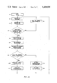
- FIGS. 6A-6C and 7A-7E show an example of waveforms used in generating modulated tones in FIG. 5;
- FIG. 8 shows a modified circuit for the modulator section 41 in FIG. 5;
- FIGS. 9A and 9B show one example of a signal composition which is sent from the paging receiver
- FIG. 10 is a block diagram of one embodiment of the tone receiver at a paging terminal.
- FIG. 11 is a modified block diagram illustrating the attachment of a visual display function to the receiver of FIG. 5.
- step numbers in the flow charts of FIGS. 2A and 2B will be given parenthesized after references to the respectively corresponding steps.
- a person (the caller) wishing to contact a person (or recipient) holding a paging receiver 16, (FIG. 1) dials the paging number of the receiver 16, the dialing being from a telephone set 1 (Steps 1 and 2 in FIG. 2A).
- This dialled number signal is sent by way of an ordinary telephone exchange office 2 to a paging service telephone exchange office 3. There it is further transferred by way of an unoccupied truck circuit (a trunk circuit 5, for instance) to an unoccupied multifrequency (MF) receiver (a receiver 6, for instance) in a paging terminal 4 which is responsible for the processing of calls or paging numbers.
- a paging number from the multifrequency receiver 6 is received through an input/output (I/O) port 11 by a central processing unit (CPU) 12. There it is checked to determine whether or not the paging number is registered. If it is registered, the CPU 12 actuates an answer-back unit 10 to transmit a registration-valid signal to the caller (Steps 3 ⁇ 6).
- the caller After confirming the registration-valid signal, the caller uses pushbuttons or the like on the telephone set 1, to enter an input signal to the effect that his dialling is for "calling" a paging receiver (Steps 7 and 8).
- a tone representing the "calling" order signal which is generated by the pushbutton operation, reaches the paging terminal 4 via a route which is the same route that is used for a dialled number.
- the tone signal is received and detected by a pushbutton (PB) tone receiver 7 therein, and supplied to the CPU 12 by way of the I/O port 11.
- PB pushbutton
- the CPU 12 Upon confirming the receipt of this pushbutton tone, the CPU 12 actuates the answer-back unit 10 to generate a message input instruction which informs the caller that he may now enter his message (Steps 9 and 10). As it is entered by the caller, the message is stored in a memory section 9 in the paging terminal 4 (Steps 11 and 12). The paging terminal 4 is informed of the completion of the storing of the message either by the caller appropriately operating the pushbuttons or another such means, or by a timer within the paging terminal 4 itself.
- the CPU 12 Upon completion of the storing of the message, the CPU 12 informs the caller in order to finish its accepting action.
- the caller hangs up his telephone set 1 (Step 13).
- the message from the caller may be either his telephone number or any other audible message.
- the telephone number can be entered either by a pushbutton operation or by a speech recognition device. Or, if there is a system permitting the caller's telephone number to be sent to the recipient through the switching network, as by the so-called multifrequency code signalling (MFC) system, its number can be employed as well.
- MFC multifrequency code signalling
- the CPU 12 sends the earlier accepted paging number to an encoder 13 (for example), the encoder may be a type ⁇ PD8085A device manufactured and marketed by the assignee, NEC.
- the paging number is encoded into a signal form which is receivable by the receiver 16 and is fed to a transmitter 14.
- the transmitter 14 modulates a carrier wave with the encoded signal.
- the modulated signal is radiated from a transmission antenna 15 over a radio frequency as a paging signal (Step 14). If, at this time, the recipient receiver 16 is present within the service area, the transmitted paging system will be received by the receiver 16, which informs the recipient of his being paged (Step 15).
- the recipient at receiver 16 dials his own paging number on a nearby telephone set 17 to confirm the content of the message with the paging terminal 4 (Steps, 16, 1 and 2). Although he is the paged caller who is responding from the telephone set 17, he will be referred to as the "recipient" in this context in order to distinguish him from the original caller who placed the page from the telephone set 1.
- the number dialled by the recipient from the telephone set 17 is sent to the paging terminal 4 by way of telephone exchange offices 18 and 3.
- the CPU 12 will send back from the answer-back unit 10 a registration-valid signal, the signal being sent to the telephone set 17 (Steps 3 ⁇ 6).
- the recipient presses an "answer" pushbutton on 17. The recipient thus enters, by pressing pushbuttons on the telephone set 17, the information that his dialling is for an "answer" to the page (Steps 7 and 8).
- the CPU 12 Upon confirmation of the "answer" order signal, the CPU 12 sends to the recipient a signal which instructs him to transmit his identification (ID) code (Steps 9 and 17).
- the recipient by means of the receiver 16, transmits his ID code in a tone form from the telephone set 17 (Step 18). (The transmission of this tone will be described hereinafter in detail).
- the tone representing the ID code is received by a tone receiver 8 and fed to the CPU 12.
- the CPU Upon receiving the ID code which is so transmitted, the CPU informs the recipient that the ID code is correct, if it is, and at the same time reproduces and transmits the message stored in the memory section 9 (Steps 19 and 20). After receiving the message, the recipient hangs up the telephone set 17 to complete the whole process (Steps 21 and 24).
- the arrangement can be modified so that, after receiving the message of Step 21 of the flow charted in FIG. 2B, the recipient can enter with pushbuttons the information that he desires to complete the connection of a Super-Bell.
- the CPU 12 in response to this input, can connect the two telephone sets by joining the trunk circuit 5 of the telephone set 17 with the trunk circuit 5 which is to be linked to the telephone set 1 (Steps 22 and 23).
- Step 7 in FIG. 2A After the dial connection (Step 7 in FIG. 2A), a distinction between a "calling" to the receiver 16 and an "answer" from the recipient is entered by a pushbutton operation, as described in the foregoing description.
- this confirmation with pushbuttons can be dispensed with if a special number, exclusive for the "answer" use, is assigned to the paging terminal 4, this special number being separate from the paging number of the receiver 16.
- FIG. 3 is a block diagram illustrating one embodiment, according to the present invention, of the paging receiver 16, referred to in FIG. 1.
- a paging signal is sent from the paging terminal 4 (FIG. 1) and is received by an antenna 21.
- that signal is supplied to a signal detection section 25.
- the signal detection section 25 reads out the paging number stored in advance in a read only memory (ROM) 23 and compares the demodulated paging number with the paging number read out of the ROM 23. If the compared numbers are identical with each other signal detection section 25, will give an identity signal.
- ROM read only memory
- An annunciator 26 informs the recipient that he is being paged by generating an audible sound in response to the identity signal.
- a section 100 may comprise circuits, such as those disclosed in U.S. Pat. No. 4,127,846 issued to Mori et al. on Nov. 28, 1978 or U.S. Pat. No. 4,194,153 issued to Masaki et al. on Mar. 18, 1980.
- the recipient uses a nearby telephone set to form the paging terminal that he is answering a paging call (Step 8 in FIG. 2A). Then he transmits the ID code number in a tone form in the following manner.
- An external switching section 24 is operated to block the output of the signal detection section 25, and at the same time the ROM 23 is actuated to supply the paging number signal of the receiver to a modulator 28.
- the modulator 28 modulates the paging number signal from the ROM 23 on to a carrier signal from an oscillator 27, thereby generating signals of a frequency (usually 300 Hz ⁇ 3 KHz) that can pass over a telephone line. Finally, this modulated signal is supplied to the annunciator 26, where the signal is converted into a tone, to be emitted.
- FIG. 4A shows a perspective view of a paging receiver according to the present invention
- FIG. 4B illustrates how this receiver is used to access a telephone set.
- a carrier wave is modulated in the station of FIG. 1 with the paging signal and transmitted from the transmitter 14 of a paging terminal, to an antenna 34 (FIG. 5) of a receiving section 35, where it is demodulated.
- the paging signal comprises a preamble signal followed by a paging number signal.
- the demodulated signal from the receiving section 35 is led to a signal detecting section 36 in which a preamble signal detector 361 produces an actuating signal, if it detects the preamble signal of the paging signal.
- the preamble signal detector 36 achieves the frame synchronization, and supplies the actuating signal by way of an AND gate 391 and an OR gate 392 of a switching section 39 to a shift register 381 in a read-out signal generator section 38, for reading out the content of a memory section 37 (for instance, a programmable read-only memory: PROM) where the paging number of the receiver is stored.
- PROM programmable read-only memory
- the paging number stored in the PROM 37 and read out by the shift register 381 is led by way of an AND gate 402 of another switching section 40 to a paging number signal detector 362 in the signal detecting section 36.
- the detector 362 compares the paging number digital signal read out of memory 37 with the output of the receiving section 35, i.e. the paging number of the called party. If the two numbers are identical with each other, detector 362 generates an identity signal, which is supplied to a frequency divider (or multiplier) 363.
- the divider 363, is composed, for instance, of a combination of flipflops or the like.
- Circuit 363 is actuated in response to the identity signal and to a clock recovery circuit 47, to generate a sequence of pulses having a desired cycle of repeated pulses, such as the pulses shown in FIG. 6A, for example.
- the pulses (FIG. 6A) are supplied to a modulator section 41 (FIG. 5).
- a signal from an audible tone oscillator section 42 is modulated with the pulses from divider 363. Modulation occurs in an AND gate 411 to provide a signal, as shown in FIG. 6C, which is supplied as output of the modulator section 41 by way of an OR gate 412.
- the output tone signal from the modulator section 41 is amplified by an amplifier 43, and then is emitted from an annunciator 44 as a tone (an audible sound), which lets the recipient know that he is being paged.
- the audible tone oscillator 42 provides an audible frequency signal by frequency-dividing (or frequency-multiplying) the oscillation output from an oscillation section 45, which has a fixed oscillation frequency responsive to the driving of an oscillating element 46, which should be either a crystal or ceramic oscillator that is stable in oscillating operation, even under fluctuating voltage and/or temperature.
- the output of the oscillation section 45 is also supplied to the clock recovery circuit 47, where synchronization clock pulses are recovered from the paging signal to achieve a synchronization between the signal detecting section 36 and the read-out signal generator section 38.
- the logic level "1" of a point M is supplied from a battery 50 by way of a switch 49.
- the logic level is switched to a logic level "0" by grounding the point M with an external switch 48.
- This action blocks the actuating signal from the preamble signal detector 361 to the shift register 381.
- an inverter 393 supplies the shift register 381 with another actuating signal having a logic level of "1", in place of the output of the detector 361.
- a paging number digital signal is sent from the PROM 37 to the paging number signal detector 362 and then is directly supplied to the modulator section 41.
- the point M is connected to the switching section 40 (including AND gates 401 and 402 and an inverter 403) and to the modulator section 41 (including AND gates 411 and 414, an OR gate 412 and an inverter 413).
- the modulation input signal which is supplied to the modulator section 41, from the signal detecting section 36, can be the paging number digital signal which is provided from the PROM 37 via the switching section 40.
- the signal from the switch 48 is also supplied to a clock rate switching circuit 382 of the read-out signal generator section 38.
- the clock rate switching circuit 382 can comprises, for instance, two flipflops and a transistor switch. The reason why the read-out rate of this PROM 37 is varied, will be explained later.
- the read-out signal generator section 38 is actuated by the external switch 48, to read out of the PROM 37 a paging number digital signal corresponding to the paging number of the receiver.
- This paging number digital signal is a signal such as shown in FIG. 7A. It entered by way of the switching section 40 into the modulator section 41, which modulates the output of the audible tone oscillator section 42, with this input digital signal.
- the output of the audible tone oscillator 42 is a signal of a continuous frequency f1 as shown in FIG. 7B, i.e., a tone signal, which is modulated with a signal (such as shown in FIG. 7A) into that shown in FIG. 7C.
- FIG. 7B i.e., a tone signal
- the modulated signal of the frequency f1 occures when the output of the PROM 37 (FIG. 7A) is logic "1"; However, the modulated signal may as well occur when it is logic "0".
- the tone signal, so modulated passes through the amplifier 43, and is emitted from the annunciator 44, as an audible tone.
- the annunciator 44 if it is structured and installed as illustrated in FIGS. 4A and 4B, can transmit the paging number of the receiver to the paging terminal in a tone form when the annunciator-equipped face of the housing and the mouthpiece of the telephone set are brought together.
- the FSK (frequency shift keying) signaling system may also be used, in which the audible tone oscillator 42 supplies tone signals having two frequencies f1 and f2, respectively, corresponding to binary signals "1" and "0".
- FIG. 8 illustrates an embodiment of the modulator section (for box 41, FIG. 5) for realizing this FSK system, wherein an inverter 415, AND gates 416 and 417, and an OR gate 418 are used in place of the inverter 413 and the AND gate 414 of the demodulator section shown in FIG. 5.
- an output signal taken from the PROM 37
- tone signals (FIGS. 7B and 7D) having the frequencies f1 and f2 from the audible tone oscillator 42 (FIG. 5) are supplied to terminals B and C, a terminal D will give the tone signal of the frequency f1, if the input to the terminal A is logic "1", or the tone signal will be the frequency f2 if the input is logic "0".
- the FSK signal which is so obtained will be as illustrated in FIG. 7E.
- the tone signals of the frequencies f1 and f2 can be readily obtained by composing the audible tone oscillator 42, for instance, by a frequency divider comprising several stages flip flops connected in series and by tapping one of its intermediate stages for an output signal.
- the tone transmission from the recipient is not necessarily limited to a single transmission. If the switching section 39 (FIG. 5) is provided with a timing circuit 394, so that the content of the PROM 37 be read plural many times in response to the action of the external switch 48, the tone can be transmitted more than once to correspondingly improve the reception reliability on the part of the paging terminal. This repeated transmission is shown in FIGS. 9A and 9B, in which each transmission signal comprises the preamble signal 51 and the paging number signal 52.
- the read-out signal intervals of the read-out signal generator section 38 may or may not differ, in terms of the length of time per bit.
- the read out intervals of the generator section 38 depends upon whether the modulator section 41 is actuated by the receiving i.e., by the signal detection section 36, or by an external switching signal.
- the tone receiver 8 of the paging terminal 4, illustrated in FIG. 1, is similar to the MF receiver 6, and comprises a band-pass filter and a detector for converting a tone signal into a direct current.
- FIG. 10 is a block diagram illustrating one embodiment of this tone receiver, for use when the recipient transmits an FSK signal as shown in FIG. 7E.
- It comprises a pair of band-pass filters 55 and 56 respectively having center frequencies equal to the two frequencies of the FSK signal, detectors 57 and 58 for converting the output tone signals of the filters 55 and 56 into D.C. components, and a waveform shaping section 59 for comparing the output voltages of the detectors 57 and 58 to provide a signal, as shown in FIG. 7A. Narrowing the pass bandwidths of the band-pass filters 55 and 56 and thereby increasing their filtering performances would result in prolonging their response times and in the need for a correspondingly longer time period, per bit, for the tone transmission from the recipient.
- the time required, per bit, for the tone transmitted from the recipient has to be varied according to the response speeds of the band-pass filters 55,56 of the tone receiver 8 which are provided at the paging terminal 4.
- the read-out signal generator section 38 (FIG. 5) is provided with a clock rate switching circuit 382.
- the band widths of filters at the paging terminal can be sufficiently narrowed if the time per bit is set as desired and if a highly stable oscillating element is used as the signal source of the paging receiving. Therefore, noise can be suppressed to an acceptably low level.
- the reliability of the paging receiver (FIG. 5) also deserves consideration.
- a digital paging system by which the radio frequency transmitted from the transmitter is modulated with digital paging signals "1" and "0", as disclosed in the Masaki et al. U.S. Pat. No. 4,194,153 referred to above.
- Paging signals used in this system are susceptible to a marked deterioration in reliability, due to the fading and noise in a radio propagation path.
- codes with error detecting or error correcting functions such as the Hamming code or the BCH code, are used as paging number codes.
- Such codes are composed of check bits which are added to the information bits in the paging digital signal.
- the check bits are transmitted and received in the following manner.
- An encoder at the paging terminal converts a paging number assigned to the paging receiver into a code in which the check bits are added to the information bits, which is then transmitted to the paging receiver.
- the memory section of the paging receiver stores its own paging number either in a form where check bits are added to information bits or in an information bit form. If the paging number is stored in the memory section in the form in which check bits are added to information bits, when the recipient responds to a call from the paging terminal, its ID code signal consists of information bits and check bits which are added to them as they are directly transmitted, by the operation of the external switching section 48 as referred to in FIG.
- the CPU 12 (FIG. 1) corrects errors in the ID code with the check bits and thereby corrects defects in the ID code.
- the signal detecting section is provided with a calculating circuit for figuring out check bits from information bits. Signals obtained from this calculating circuit can afford the same effect as the afore-mentioned system in which information bits and check bits are stored in the memory section.
- Erroneous reception may be due to noise or the like.
- erroneous reception can also arise from a mishandling by the recipient, which mishandling can be effectively prevented by the following method.
- the recipient operates the external switching section of his receiver, to transmit its number to the paging terminal, the fact that the signal is being transmitted is indicated on a display unit on a part of the exterior of the receiver housing.
- FIG. 11 illustrates one embodiment of this method, which can be realized by adding such a circuit to the receiver of FIG. 5.
- the modification of FIG. 5 comprises a display unit 62 (FIG. 11) and a display driving section 61 which includes a driving circuit 612 and an RS flipflop 611, having a set and a reset terminal respectively which receive the read-out signals appearing on lines L 1 and L n .
- the read-out signal generator 38 provides the read-out signals to the PROM 37, in the line order L 1 -L n .
- the signals appearing on lines L 1 and L n are respectively the start and the finish signals of the read-out. Therefore, the display unit 62 turns on during the period while the tone representing the ID code is being transmitted.
- the display unit 62 can comprise, for instance, an LED (a light emitting diode), an LCD (a liquid crystal display) or an ECD (electro-chromic display). This arrangement can make it known to the recipient that the receiver is sending out its paging number and thereby prevent the recipient from erroneously mishandling the receiver.
- the hitherto described paging receiver for use in the system of the present invention, as illustrated in FIG. 3 or FIG. 5, is highly economical because it can share a large majority of parts with a conventional receiver, with the addition of only a limited number of circuit components including an external switching section. This feature also contributes to making the hardware compact, and invites no deterioration in reliability owing to an increase in the number of components.
- the radio paging system enables the recipient to take out a message, by the use of an existing telephone line.
- the message from the calling subscriber is stored at the paging terminal.
- the invention keeps its equipment and operating costs remarkably low.
- no specified number has to be used for taking out the message. Thus, the trouble of registering the number of mishandlings by the recipient can be minimized, if not fully obviated.
Abstract
Description
Claims (10)
Applications Claiming Priority (2)
| Application Number | Priority Date | Filing Date | Title |
|---|---|---|---|
| JP8002580A JPS5720040A (en) | 1980-06-13 | 1980-06-13 | Radio individual selective calling system |
| JP55-80025 | 1980-06-13 |
Publications (1)
| Publication Number | Publication Date |
|---|---|
| US4408099A true US4408099A (en) | 1983-10-04 |
Family
ID=13706733
Family Applications (1)
| Application Number | Title | Priority Date | Filing Date |
|---|---|---|---|
| US06/270,992 Expired - Lifetime US4408099A (en) | 1980-06-13 | 1981-06-05 | Radio paging system capable of accepting message with access of paging receiver |
Country Status (6)
| Country | Link |
|---|---|
| US (1) | US4408099A (en) |
| JP (1) | JPS5720040A (en) |
| AU (1) | AU538914B2 (en) |
| CA (1) | CA1186381A (en) |
| GB (1) | GB2078467B (en) |
| HK (1) | HK80189A (en) |
Cited By (24)
| Publication number | Priority date | Publication date | Assignee | Title |
|---|---|---|---|---|
| US4490579A (en) * | 1983-04-15 | 1984-12-25 | Vanig Godoshian | Auto-dialing pager receiver |
| US4575582A (en) * | 1983-10-28 | 1986-03-11 | Nec Corporation | Mobile radio communications system |
| WO1987000994A1 (en) * | 1985-08-08 | 1987-02-12 | Network Satellite Paging Partners, Ltd. | Nationwide radio paging system |
| US4796291A (en) * | 1983-10-28 | 1989-01-03 | Nec Corporation | Mobile radio communications system |
| US4864301A (en) * | 1987-07-24 | 1989-09-05 | Richard J. Helferich | Variable speed transmission recording and retrieval of data |
| US4905003A (en) * | 1987-07-24 | 1990-02-27 | Richard J. Helferich | Analog/digital data storage system |
| US4951043A (en) * | 1986-03-04 | 1990-08-21 | Nec Corporation | Pager receiver helpful for effective use of call numbers |
| US5003576A (en) * | 1987-07-24 | 1991-03-26 | Richard J. Helferich | Analog/digital voice storage cellular telephone |
| US5247700A (en) * | 1990-11-16 | 1993-09-21 | Universal Cellular, Inc. | Cellular telephone with pager |
| US5293418A (en) * | 1990-06-20 | 1994-03-08 | Any Co., Ltd. | Mobile terminal equipment capable of storing called state |
| WO1995001038A1 (en) * | 1993-06-17 | 1995-01-05 | Motorola, Inc. | Paging system with voice recognition |
| USRE34976E (en) * | 1987-07-24 | 1995-06-20 | Richard J. Helferich | Analog/digital voice storage cellular telephone |
| US5544224A (en) * | 1993-05-20 | 1996-08-06 | Telefonaktiebolaget Lm Ericsson | Reestablishment |
| US5592532A (en) * | 1991-04-12 | 1997-01-07 | Canon Kabushiki Kaisha | Wireless telephone system with message storage for plural telephones |
| US5828311A (en) * | 1995-10-10 | 1998-10-27 | Telefonaktiebolaget L M Ericsson (Publ.) | Circuitry and method for accessing a radio pager |
| US6275680B1 (en) * | 1997-07-29 | 2001-08-14 | Philips Semiconductors, Inc. | Hardware PCH checking for personal handyphone system portable station |
| US6278862B1 (en) | 1994-01-05 | 2001-08-21 | Daniel A. Henderson | Method and apparatus for enhancing the efficient communication of information in an alphanumeric paging network |
| USRE37618E1 (en) * | 1987-07-24 | 2002-04-02 | Richard J. Helferich | Analog/digital data storage system |
| US6427064B1 (en) | 1994-01-05 | 2002-07-30 | Daniel A. Henderson | Method and apparatus for maintaining a database in a portable communication device |
| US6459910B1 (en) * | 1995-06-07 | 2002-10-01 | Texas Instruments Incorporated | Use of speech recognition in pager and mobile telephone applications |
| US20050148324A1 (en) * | 1997-09-26 | 2005-07-07 | Henderson Daniel A. | Method and apparatus for an improved call interrupt feature in a cordless telephone answering device |
| US7142846B1 (en) | 1994-01-05 | 2006-11-28 | Henderson Daniel A | Method and apparatus for improved paging receiver and system |
| US7251318B1 (en) * | 1994-01-05 | 2007-07-31 | Intellect Wireless Inc. | Method and apparatus for improved personal communication devices and systems |
| US7257210B1 (en) | 1994-01-05 | 2007-08-14 | Intellect Wireless Inc. | Picture phone with caller id |
Families Citing this family (5)
| Publication number | Priority date | Publication date | Assignee | Title |
|---|---|---|---|---|
| JPS5994931A (en) * | 1982-11-22 | 1984-05-31 | Toshiba Corp | Paging system |
| DE3329307A1 (en) * | 1983-08-12 | 1985-02-28 | Siemens AG, 1000 Berlin und 8000 München | Process in a telephone system for the connection of mobile subscriber terminals |
| JPH01146436A (en) * | 1987-12-02 | 1989-06-08 | Taiyo Kagaku Co Ltd | Radio paging system |
| JPH01151834A (en) * | 1988-06-27 | 1989-06-14 | Toshiba Corp | Communication system |
| JPH0556079U (en) * | 1991-12-27 | 1993-07-27 | ジューキ株式会社 | Two-needle sewing machine needle thread feeder |
Citations (4)
| Publication number | Priority date | Publication date | Assignee | Title |
|---|---|---|---|---|
| US3836726A (en) * | 1971-10-25 | 1974-09-17 | Martin Marietta Corp | Data transmission method and apparatus |
| GB2024567A (en) * | 1978-04-18 | 1980-01-09 | Nippon Electric Co | Digital radio pager |
| US4194153A (en) * | 1977-09-16 | 1980-03-18 | Nippon Electric Co., Ltd. | Digital radio paging communication system |
| US4263480A (en) * | 1979-07-17 | 1981-04-21 | Levine Alfred B | Pager receiver |
Family Cites Families (3)
| Publication number | Priority date | Publication date | Assignee | Title |
|---|---|---|---|---|
| JPS5115673B2 (en) * | 1971-09-23 | 1976-05-18 | ||
| JPS5326443B2 (en) * | 1972-04-24 | 1978-08-02 | ||
| GB2016768B (en) * | 1978-01-25 | 1982-05-06 | Multitone Electric Co Ltd | Paging receiver |
-
1980
- 1980-06-13 JP JP8002580A patent/JPS5720040A/en active Granted
-
1981
- 1981-06-05 US US06/270,992 patent/US4408099A/en not_active Expired - Lifetime
- 1981-06-12 AU AU71677/81A patent/AU538914B2/en not_active Expired
- 1981-06-12 CA CA000379662A patent/CA1186381A/en not_active Expired
- 1981-06-12 GB GB8118113A patent/GB2078467B/en not_active Expired
-
1989
- 1989-10-12 HK HK801/89A patent/HK80189A/en not_active IP Right Cessation
Patent Citations (4)
| Publication number | Priority date | Publication date | Assignee | Title |
|---|---|---|---|---|
| US3836726A (en) * | 1971-10-25 | 1974-09-17 | Martin Marietta Corp | Data transmission method and apparatus |
| US4194153A (en) * | 1977-09-16 | 1980-03-18 | Nippon Electric Co., Ltd. | Digital radio paging communication system |
| GB2024567A (en) * | 1978-04-18 | 1980-01-09 | Nippon Electric Co | Digital radio pager |
| US4263480A (en) * | 1979-07-17 | 1981-04-21 | Levine Alfred B | Pager receiver |
Cited By (34)
| Publication number | Priority date | Publication date | Assignee | Title |
|---|---|---|---|---|
| US4490579A (en) * | 1983-04-15 | 1984-12-25 | Vanig Godoshian | Auto-dialing pager receiver |
| US4575582A (en) * | 1983-10-28 | 1986-03-11 | Nec Corporation | Mobile radio communications system |
| US4796291A (en) * | 1983-10-28 | 1989-01-03 | Nec Corporation | Mobile radio communications system |
| WO1987000994A1 (en) * | 1985-08-08 | 1987-02-12 | Network Satellite Paging Partners, Ltd. | Nationwide radio paging system |
| US4951043A (en) * | 1986-03-04 | 1990-08-21 | Nec Corporation | Pager receiver helpful for effective use of call numbers |
| US4905003A (en) * | 1987-07-24 | 1990-02-27 | Richard J. Helferich | Analog/digital data storage system |
| US4864301A (en) * | 1987-07-24 | 1989-09-05 | Richard J. Helferich | Variable speed transmission recording and retrieval of data |
| US5003576A (en) * | 1987-07-24 | 1991-03-26 | Richard J. Helferich | Analog/digital voice storage cellular telephone |
| USRE34976E (en) * | 1987-07-24 | 1995-06-20 | Richard J. Helferich | Analog/digital voice storage cellular telephone |
| USRE37618E1 (en) * | 1987-07-24 | 2002-04-02 | Richard J. Helferich | Analog/digital data storage system |
| US5293418A (en) * | 1990-06-20 | 1994-03-08 | Any Co., Ltd. | Mobile terminal equipment capable of storing called state |
| US5247700A (en) * | 1990-11-16 | 1993-09-21 | Universal Cellular, Inc. | Cellular telephone with pager |
| US5592532A (en) * | 1991-04-12 | 1997-01-07 | Canon Kabushiki Kaisha | Wireless telephone system with message storage for plural telephones |
| US5544224A (en) * | 1993-05-20 | 1996-08-06 | Telefonaktiebolaget Lm Ericsson | Reestablishment |
| WO1995001038A1 (en) * | 1993-06-17 | 1995-01-05 | Motorola, Inc. | Paging system with voice recognition |
| US6278862B1 (en) | 1994-01-05 | 2001-08-21 | Daniel A. Henderson | Method and apparatus for enhancing the efficient communication of information in an alphanumeric paging network |
| US7308088B1 (en) | 1994-01-05 | 2007-12-11 | Intellect Wireless, Inc. | Method and apparatus for improved personal communication devices and systems |
| US7454000B1 (en) | 1994-01-05 | 2008-11-18 | Intellect Wireless, Inc. | Method and apparatus for improved personal communication devices and systems |
| US6427064B1 (en) | 1994-01-05 | 2002-07-30 | Daniel A. Henderson | Method and apparatus for maintaining a database in a portable communication device |
| US7426264B1 (en) * | 1994-01-05 | 2008-09-16 | Henderson Daniel A | Method and apparatus for improved personal communication devices and systems |
| US7349532B2 (en) | 1994-01-05 | 2008-03-25 | Intellect Wireless Inc. | Picture and video message center system |
| US7142846B1 (en) | 1994-01-05 | 2006-11-28 | Henderson Daniel A | Method and apparatus for improved paging receiver and system |
| US7251318B1 (en) * | 1994-01-05 | 2007-07-31 | Intellect Wireless Inc. | Method and apparatus for improved personal communication devices and systems |
| US7254223B1 (en) * | 1994-01-05 | 2007-08-07 | Intellect Wireless Inc. | Method and apparatus for improved personal communication devices and systems |
| US7257210B1 (en) | 1994-01-05 | 2007-08-14 | Intellect Wireless Inc. | Picture phone with caller id |
| US7266186B1 (en) | 1994-01-05 | 2007-09-04 | Intellect Wireless Inc. | Method and apparatus for improved paging receiver and system |
| US7286658B1 (en) | 1994-01-05 | 2007-10-23 | Intellect Wireless Inc. | Method and apparatus for improved personal communication devices and systems |
| US7305076B1 (en) | 1994-01-05 | 2007-12-04 | Intellect Wireless Inc. | Method and apparatus for improved paging receiver and system |
| US20070293205A1 (en) * | 1994-01-05 | 2007-12-20 | Henderson Daniel A | Method and apparatus for improved personal communication devices and systems |
| US7310416B1 (en) | 1994-01-05 | 2007-12-18 | Intellect Wireless Inc. | Method and apparatus for improved personal communication devices and systems |
| US6459910B1 (en) * | 1995-06-07 | 2002-10-01 | Texas Instruments Incorporated | Use of speech recognition in pager and mobile telephone applications |
| US5828311A (en) * | 1995-10-10 | 1998-10-27 | Telefonaktiebolaget L M Ericsson (Publ.) | Circuitry and method for accessing a radio pager |
| US6275680B1 (en) * | 1997-07-29 | 2001-08-14 | Philips Semiconductors, Inc. | Hardware PCH checking for personal handyphone system portable station |
| US20050148324A1 (en) * | 1997-09-26 | 2005-07-07 | Henderson Daniel A. | Method and apparatus for an improved call interrupt feature in a cordless telephone answering device |
Also Published As
| Publication number | Publication date |
|---|---|
| AU538914B2 (en) | 1984-08-30 |
| HK80189A (en) | 1989-10-20 |
| GB2078467A (en) | 1982-01-06 |
| GB2078467B (en) | 1985-02-13 |
| JPS5720040A (en) | 1982-02-02 |
| AU7167781A (en) | 1981-12-17 |
| CA1186381A (en) | 1985-04-30 |
| JPS6351418B2 (en) | 1988-10-13 |
Similar Documents
| Publication | Publication Date | Title |
|---|---|---|
| US4408099A (en) | Radio paging system capable of accepting message with access of paging receiver | |
| EP0818915B1 (en) | Methods and apparatus for initiating wireless messages | |
| EP0108938B1 (en) | Digital paging system having bit rate switching means and digital paging receiver therefor | |
| US4415770A (en) | Malfunction detection system for a mobile radio telephone system | |
| US4194153A (en) | Digital radio paging communication system | |
| US4680785A (en) | Personal-signaling communication system | |
| US5404579A (en) | Dual mode mobile radio communication apparatus with function for transmitting remote control data | |
| US5917887A (en) | Emergency alert communication system wherein emergency messages are received by a radio frequency receiver and routed to a telephone device | |
| US5315645A (en) | Communication apparatus utilizing digital optical signals | |
| EP0218450B1 (en) | Control system of a radio telephone apparatus | |
| US4947420A (en) | Communication system | |
| US6411808B1 (en) | Portable terminal equipment | |
| US5291192A (en) | Paging system and its operating method with repeated transmission | |
| EP0176215B1 (en) | Improvements to cordless telephones | |
| KR930002882B1 (en) | Radio telephone set | |
| GB2298552A (en) | Cordless radio telephone system with a plurality of portable units | |
| JP2752994B2 (en) | Wireless telephone equipment | |
| EP0193972B1 (en) | Mf signal transmitting control apparatus/method for use in cordless telephone system | |
| JP2518903B2 (en) | Phone extension system | |
| US5428672A (en) | Communication apparatus | |
| JPH07226968A (en) | Radio calling device | |
| JPH08289350A (en) | Portable communication terminal equipment | |
| JP3808617B2 (en) | Telephone equipment | |
| JPS6286932A (en) | Selective calling system for radio station | |
| JPS60100895A (en) | Dial device |
Legal Events
| Date | Code | Title | Description |
|---|---|---|---|
| AS | Assignment |
Owner name: NIPPON ELECTRIC CO., LTD., 33-1, SHIBA GOCHOME, MI Free format text: ASSIGNMENT OF ASSIGNORS INTEREST.;ASSIGNOR:ISHII DAISUKE;REEL/FRAME:003880/0651 Effective date: 19810602 Owner name: NIPPON ELECTRIC CO., LTD., JAPAN Free format text: ASSIGNMENT OF ASSIGNORS INTEREST;ASSIGNOR:ISHII DAISUKE;REEL/FRAME:003880/0651 Effective date: 19810602 |
|
| STCF | Information on status: patent grant |
Free format text: PATENTED CASE |
|
| MAFP | Maintenance fee payment |
Free format text: PAYMENT OF MAINTENANCE FEE, 4TH YEAR, PL 96-517 (ORIGINAL EVENT CODE: M170); ENTITY STATUS OF PATENT OWNER: LARGE ENTITY Year of fee payment: 4 |
|
| FEPP | Fee payment procedure |
Free format text: PAYOR NUMBER ASSIGNED (ORIGINAL EVENT CODE: ASPN); ENTITY STATUS OF PATENT OWNER: LARGE ENTITY |
|
| MAFP | Maintenance fee payment |
Free format text: PAYMENT OF MAINTENANCE FEE, 8TH YEAR, PL 96-517 (ORIGINAL EVENT CODE: M171); ENTITY STATUS OF PATENT OWNER: LARGE ENTITY Year of fee payment: 8 |
|
| MAFP | Maintenance fee payment |
Free format text: PAYMENT OF MAINTENANCE FEE, 12TH YEAR, LARGE ENTITY (ORIGINAL EVENT CODE: M185); ENTITY STATUS OF PATENT OWNER: LARGE ENTITY Year of fee payment: 12 |