US4403235A - Optical scanning and imaging system utilizing laser diode - Google Patents
Optical scanning and imaging system utilizing laser diode Download PDFInfo
- Publication number
- US4403235A US4403235A US06/276,260 US27626081A US4403235A US 4403235 A US4403235 A US 4403235A US 27626081 A US27626081 A US 27626081A US 4403235 A US4403235 A US 4403235A
- Authority
- US
- United States
- Prior art keywords
- drum
- mirror assembly
- light
- optical
- laser
- Prior art date
- Legal status (The legal status is an assumption and is not a legal conclusion. Google has not performed a legal analysis and makes no representation as to the accuracy of the status listed.)
- Expired - Fee Related
Links
Images


Classifications
-
- G—PHYSICS
- G02—OPTICS
- G02B—OPTICAL ELEMENTS, SYSTEMS OR APPARATUS
- G02B26/00—Optical devices or arrangements for the control of light using movable or deformable optical elements
- G02B26/08—Optical devices or arrangements for the control of light using movable or deformable optical elements for controlling the direction of light
- G02B26/10—Scanning systems
- G02B26/12—Scanning systems using multifaceted mirrors
-
- H—ELECTRICITY
- H04—ELECTRIC COMMUNICATION TECHNIQUE
- H04N—PICTORIAL COMMUNICATION, e.g. TELEVISION
- H04N1/00—Scanning, transmission or reproduction of documents or the like, e.g. facsimile transmission; Details thereof
- H04N1/024—Details of scanning heads ; Means for illuminating the original
- H04N1/032—Details of scanning heads ; Means for illuminating the original for picture information reproduction
- H04N1/036—Details of scanning heads ; Means for illuminating the original for picture information reproduction for optical reproduction
-
- H—ELECTRICITY
- H04—ELECTRIC COMMUNICATION TECHNIQUE
- H04N—PICTORIAL COMMUNICATION, e.g. TELEVISION
- H04N1/00—Scanning, transmission or reproduction of documents or the like, e.g. facsimile transmission; Details thereof
- H04N1/04—Scanning arrangements, i.e. arrangements for the displacement of active reading or reproducing elements relative to the original or reproducing medium, or vice versa
- H04N1/113—Scanning arrangements, i.e. arrangements for the displacement of active reading or reproducing elements relative to the original or reproducing medium, or vice versa using oscillating or rotating mirrors
- H04N1/1135—Scanning arrangements, i.e. arrangements for the displacement of active reading or reproducing elements relative to the original or reproducing medium, or vice versa using oscillating or rotating mirrors for the main-scan only
Definitions
- This invention relates to photo-optical scanning apparatus utilizing a laser diode light generating device and a polygonal mirror assembly in conjunction with suitable light beam collimating and focussing apparatus. More specifically, the invention relates to a system for precisely shaping the laser generating light beam into an efficient spot scanning size for electrophotographic printing and/or copying.
- Another problem is associated with the location of the laser light generating apparatus and its angular relationship to the operably associated hardware.
- a further problem is that as the polygon mirror assembly is rotated at a constant rotational rate the speed of the generated spot will be constant along an arc but will not be constant with respect to a straight line scan. In fact, the laser beam or spot speeds up at the periphery of the scan line which in turn has the effect of changing the dimension of the output data being developed.
- a novel aspect of the invention is the provision for the apparatus to be modularly related and to be mounted to a rigid, fixed base member.
- Each element of the novel combination is adjustably, positionable relative to the base as well as to the axis of the laser beam, the lenses, mirrors and polygonal mirror facets thereby insuring an accurate, clear and highly defined, latent image on the photoconductor i.e. drum.
- Another novel aspect of the present invention is the provision of a novel photoconductor drum charging, exposing, toning and cleaning apparatus for a laser diode and printing and/or copying apparatus utilizing a novel folded laser scanning light path in combination with a corna charging, discharging apparatus not heretofore available in electrophotographic processing apparatus.
- FIG. 1 is a schematic side elevational view, not to scale, of apparatus embodying the present invention
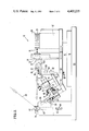
- FIG. 2 is a detailed side elevational view of the apparatus of FIG. 1;
- FIG. 3 is a schematic top end view not to scale, of the apparatus of FIGS. 1 and 2;
- FIG. 4 is a detailed top plan view of the apparatus of FIG. 3;
- FIG. 5 is a schematic illustration, not to scale, of the electrophotographic process station of the present invention.
- FIG. 6 is a detailed view of the apparatus illustrated in FIG. 5.
- the now collimated, altered, beam 24 of light is next directed through a focussing lens 26 to a rotatable polygonal mirror assembly 28.
- the focussed light beam 30 is reflected off the faces or facets of the polygon 28 as the latter is rotated by drive motor 32 in the direction of arrow 34.
- the rays 36 of the reflected beam are focused onto the photoconductive drum surface 38 of rotatable drum 40 via a tiltable mirror assembly 42 and a second focussing lens system 44, FIG. 1.
- the focussed laser beam 46 is adapted to scan the cylindrical photoconductor surface 38 from edge to edge or side to side by means of the rotating polygon mirror 28 and drive motor 28. Modulation (by means not shown) of the laser diode 12 produces a latent electrostatic image upon the surface 38 of photoconductor 40.
- Copying and/or printing media 48, FIGS. 5 and 6, is adapted to receive the image of the intelligence carried by the latent electrostatic image by means of and in a manner to be described later on herein.
- FIG. 1 A physical embodiment of the apparatus 10 schematically illustrated in FIG. 1 is seen most clearly in the side elevational view of FIG. 2, to comprise a rigid base member 50 on which the entire assembly is mounted and adapted to be slideably moveable back and forth or right to left as the case may be.
- mirror 42 is adapted to be tilted about its horizontal axis mounting pivot 52 so as to fold the laser beam 36 upwardly toward the cylindrical lens 44, FIG. 1. Tilting adjustment of the mirror 42 is provided by means of the threaded horizontal cross shaft 54 adjustably moveable by means of thumb wheel 56 against the vertical mirror support column 58 disposed in vertical mounting pillar 60 secured to base 50.
- Vertical, erectable movement of mirror 42 is provided by means of slot 62 and pin 64, as seen most clearly in FIG. 2.
- the laser diode 12 (light generating element) is surrounded by a thermo-electric cooling member 66 and is gimbally mounted, as at 68 to support 70.
- a heat sink 72 of copper or similar material capable of rapidly and efficiently dissipating large quantities of heat abuts the laser diode assembly 12.
- the gimble pivoting arrangement 68 supports the heat sink 72 and cooling member 66 enabling the laser diode 12 to be pivoted about two orthogonal axes that pass directly through the diode chip.
- the laser diode temperature is regulated so as to be constant at approximately 20-21 degrees C. by a feedback controller with a thermistor sensor (not shown). It is necessary that the heat sink temperature, which is close to ambient, be somewhat above the control temperature since the thermoelectric device can only cool and cannot heat.
- the laser light 14 emitted by the diode 12 is collected by the objective lens 16 which in one embodiment comprises a microscope objective having a magnification of 20 times. This is necessary since the output area (of the diode is about two tenths micron by about five microns) from which light is being emitted and is extremely small.
- the objective lens 16 has the laser light at its focus. The light enters the lens as a diverging set of light rays 14 from the laser diode 12. The objective lens 16 collimates the light, as seen most clearly in FIG. 2. Since the light from the diode 12 is diverging on the entering side of lens 16 and is collimated on the exiting side thereof, the beam is not generally circular but rather oblong or elliptical in cross section.
- the collimated light is first passed through prism 20 which is configured so as to compress the beam in the vertical plane or direction down to approximately one tenth inch. Thereafter, the beam is redirected into and through prism 22 which is constructed such that the light beam is expanded slightly in the horizontal direction. Exiting from the second prism 22 the light beam now has a circular cros section and is collimated before entering focussing lens 26.
- each of the lenses and prisms heretofore mentioned are provided with separate means for orthogonally positioning these elements relative to each other as well as with respect to the axis of the laser light beam.
- a rigid elevating platform 74 is secured to the base 50 to which is mounted, as by bolts (not shown) a second rigid mount 76.
- Member 76 provides oppositely disposed parallel guiding tracks (not shown) for slideably moving support member 78.
- a rockably, pivoted support member 80 arcuately moveable about pivot 82 on the leftward projecting end of the member 78.
- Member 80 provides a tiltable support for the laser diode 12 including its heat sink 72 as well as for the objective lens assembly 16 and its adjusting means.
- Vertical, slideable, adjustment for diode 12 is controlled and actuated by means of micrometer slides and the knurled thumb wheel 84. The horizontal adjustment is by means of thumb wheel 86, FIG. 4.
- Rocking movement for platform 80 to axially align the laser beam 14 is provided by means of the threaded adjusting wheel 88 which is adapted to rockably pivot the member 80 about pivot 82 by means of threaded shaft 90 against the rightward end of member 80.
- Sliding, focussing adjustment for objective lens assembly 16 is provided by thumb wheel and shaft assembly 92 at the rightward end of member 80.
- Laser beam light rays 18 pass, as before mentioned, through a compression prism 20 which is angularly, adjustably mounted on a horizontal pivot 94 and tiltable about this pivot by means of thumb wheel 96, cam 98 and L-shaped follower link 100. Adjustment movement of prism 72 is accomplished by means of thumb wheel 102, FIGS. 2 and 4, cylindrical cam 104 and L-shaped cam follower 106 secured to prism 22. Focussing lens 26 is threadedly, adjustable backwards and forward for accurate focussing by rotation within the lens support 108.
- the focussed laser light beam 30 after passing through the focussing lens 26 is reflectively scanned across the surface 38 of photoconducting drum member 40 in a manner such that the data or intelligence contained in the modulated beam is placed upon the drum for copying/printing purposes, as will be hereinafter described.
- Polygon mirror 28 rotating in the direction of arrow 34 by drive motor 32 carries 20 mirror facets and rotates at the rate of 12,558 RPM.
- the laser light is passed from the focussing lens 26 to the face of each mirror facet so as to scan through an angle of 36 degrees (as the polygon rotates) which is precisely twice the angle that the facet moves through during the period of time for one scan line.
- the focussing lens 26 positioned in front of or before the polygon 28, the focal point tends to be on the arc of a sphere. Rather than in a plane this marks for correction problems since the beam 24 passes through the same point of this lens all the time.
- the deflected beam is rotating at a constant rotational rate so the speed will be constant on an arc but will not be constant on the straight scan line.
- the beam or spot speeds up at the periphery, which produces a small effect in changing the dimension of the characters.
- a focusing lens 110 is positioned after the polygon 28.
- This lens characterized as a F-theta lens (fe) and avoids the variation of lineal scan velocity with the scan angle.
- F-theta (fe) lens it is possible to make an F-theta (fe) lens so that the lineal displacement varies as the focal length times theta (fe) itself. This allows a linear relationship between polygon rotation and spot position. Plus, it produces a flatter field so that the focus is in a plane (including the scan line).
- the (Fe) lens is triplet a lens.
- the focussed light is reflected off tilt mirror 42 and angularly, upwardly into and through the elongated, focussing, cylindrical lens 44 to be raster scanned across the photoconductor 40. Only about 25 degrees of the total scan is used for the printed scan line.
- a start of scan detector (not shown) which is used to time the initiation of printing.
- Lens 44 has a flat surface on one side and convex surface on the other side and is utilized to reduce the vertical or facet apex angle error, an error in the position of the beam due to wobbling of the facets from one facet to the other, i.e., the socalled change in the apex angle. (The angle between the axis of rotation of the polygon and the facet, varies from one facet to the other and this variation causes the beam to deflect slightly in the vertical direction). Utilization of cylindrical lens 44 reduces the effect of the wobble.
- the rotating polygon causes the light to scan a full raster scan length i.e. the width of the drum or the width of the line that is to be printed on the page one scan length for each facet on the polygon.
- the raster line spacing is determined by the resolution desired for 240 dots per inch. Each raster line is spaced by 1 over 240. Thus, the raster scan lines are spaced 1/240th of an inch or 00417 inches apart.
- Dividing the raster line spacing by the velocity of the drum gives the time permitted for each scan line.
- the reciprocal of the scan line time gives the scan rate.
- the scan rate would be just equal to 17.44 inches per second by 0.00417 inches.
- the result can be expressed as 17.44 times 240 dots per inch. This gives a repetition rate for the scan in scans per second. Each scan occurs in approximately 239 microseconds.
- the more facets on the polygon the more the total RPM can be reduced.
- the present polygon has 20 facets. The number of facets is tied in with the resolution that is desired to be achieved.
- the beam must be expanded to a predetermined size as it is passed into the final focussing lens.
- the collimated beam size (aperture) should be larger to obtain a small spot.
- FIGS. 5 and 6 With emphasis first to FIG. 5, there is shown a highly schematic or diagrammatic side elevational view of the electrophotographic process station of the present invention.
- the block indentified in FIG. 5 as "optical scanning assembly” is meant, for purposes of illustration, to include the complete optical structural arrangement shown in FIG. 2 including the cylindrical focussing lens 44 through which the modulated laser beam 46 passes to impinge upon the rotatable drum 40.
- the cylindrical lens corrects for any beam motion introduced by the rotating polygon and its associated vertically disposed mirrors.
- Drum 40 is provided with a relatively hard, long wearing, photoconductive coating 38 having a high infrared response, FIG. 1 and is adapted to be rotated in the direction of arrow 112.
- the size of the drum is calculated to accept 11 inch or 14 inch length sheets of plain paper for copying/printing in serial fashion, one after the other, so as to increase the general "throughput" of the apparatus.
- the drum 40 has no surface charge on it and no toner.
- the charge coratron 114 which consists of six wires stretched across, parallel to but out of contact with the drum surface, is electrically energized placing a uniform electrical charge across the photoconductive surface 38.
- the drum 40 rotates clockwise, so that the light from the laser diode 12 strikes the areas on the drum surface where no printing is desired which discharges the background.
- the laser diode beam is swept across the length of the drum and selectively modulated with the intelligence necessary to produce the printed matter desired.
- Each scan line at a resolution of 240 dots per inch will have 240 scan lines per inch of printing.
- the dots will be generated by turning the laser diode 12 on and off to get the intelligence information on the drum.
- the drum now has selective regions of electrical charge and regions that are discharged or have no electrical charge thus forming a latent electrostatic image thereon.
- Toner station 116 has an electrical charge bias supply to the toner 118 with a polarity and magnitude such that the toner is attracted to the drum surfaces 38 in the regions corresponding to where the print will be.
- the apparatus has produced a developed image.
- the drum 40 continues to rotate further, it comes into the transfer area 120 where the image is to be transferred from the photoconductive drum to the copy material e.g. paper 48.
- Paper 48 is moved from left to right arrow 122.
- Two implementations are employed for toner transfer. Both of them use electrostatic means.
- Nonconductive toner 118 is used.
- the paper 48 is charged by means of a transfer coratron 124.
- the coratron wires develop an electrostatic charge field which essentially causes the toner to have a greater attraction towards the paper 48 and the downstream (rightward) detac coratron 126 than it does towards the photoconductive drum 40.
- the toner effectively lifts off the drum and is applied to the paper.
- the detac coratron 126 separates the paper 48 from the drum to which is electrostatically attracted.
- Detac coratron 126 applies a DC pulse at the front or leading edge of the paper to lift the leading edge up.
- an AC electrical potential is applied to member 126. This discharges the paper, the paper 48 thus is lifted off the drum with the toner intact.
- the paper carrying the toner image next passes into the fuser 128 which is a combination of pressure and heat produced by means of two opposing roller members 130 and 132, respectively. Thereafter, the paper is passed into the next station of the machine at which time the paper bears an image of the intelligence copied or printed thereon. Although greater than 98 percent of the toner is transferred to the paper 48, in order to offset the problems with residual toner on the photoconductive drum, if any, a preclean coratron 134 and preclean lamp member 136 are used. An AC coratron wire is used at this point with the AC switching polarity between positive and negative, discharges the surface of the drum 40 and also discharges the toner 118.
- a vacuum cleaning station 138 provided with a rotating bristle brush 140 of soft bristles, with a vacuum applied from a source (not shown) sucks off residual toner which may be on the drum. At this point the drum is considered to be clean as far as toner is concerned. However, since toner was covering some surfaces of the photoconductor that the light from the drum is rotated past a final discharge lamp 142. Light from lamp 142 shines onto a completely cleaned drum removes all residual charge very effectively. The apparatus is now ready to start the copy process again at the charge coratron 114.
- oppositely disposed stripper finger members 144 which protrude slightly into the drum and into recessed areas at the edges i.e. opposite sides of the paper, catch the paper and tend to lift the paper away from the drum.
Abstract
Description
Claims (10)
Priority Applications (1)
| Application Number | Priority Date | Filing Date | Title |
|---|---|---|---|
| US06/276,260 US4403235A (en) | 1981-06-23 | 1981-06-23 | Optical scanning and imaging system utilizing laser diode |
Applications Claiming Priority (1)
| Application Number | Priority Date | Filing Date | Title |
|---|---|---|---|
| US06/276,260 US4403235A (en) | 1981-06-23 | 1981-06-23 | Optical scanning and imaging system utilizing laser diode |
Publications (1)
| Publication Number | Publication Date |
|---|---|
| US4403235A true US4403235A (en) | 1983-09-06 |
Family
ID=23055900
Family Applications (1)
| Application Number | Title | Priority Date | Filing Date |
|---|---|---|---|
| US06/276,260 Expired - Fee Related US4403235A (en) | 1981-06-23 | 1981-06-23 | Optical scanning and imaging system utilizing laser diode |
Country Status (1)
| Country | Link |
|---|---|
| US (1) | US4403235A (en) |
Cited By (7)
| Publication number | Priority date | Publication date | Assignee | Title |
|---|---|---|---|---|
| DE3537857A1 (en) * | 1985-10-24 | 1987-05-07 | Hell Rudolf Dr Ing Gmbh | OPTOELECTRONIC SCAN HEAD |
| EP0314140A2 (en) * | 1987-10-30 | 1989-05-03 | Mita Industrial Co. Ltd. | Image-forming machine |
| US4948221A (en) * | 1988-08-30 | 1990-08-14 | Eastman Kodak Company | Athermalized optical head |
| US5161064A (en) * | 1990-11-21 | 1992-11-03 | Polaroid Corporation | Radiation source for a printer |
| US6490072B2 (en) | 2001-01-12 | 2002-12-03 | Lexmark International, Inc. | Mirror angle adjustment and mounting system for a laser scanner device |
| US6671107B2 (en) | 2002-04-18 | 2003-12-30 | Lexmark International, Inc. | Mounting of pre-scan optics for a laser scanning device |
| US20140267533A1 (en) * | 2013-03-14 | 2014-09-18 | Mayadah ALHASHEM | Inkless printer |
Citations (8)
| Publication number | Priority date | Publication date | Assignee | Title |
|---|---|---|---|---|
| US3720785A (en) * | 1971-02-25 | 1973-03-13 | Saxon Ind Inc | Recording system and method for copying machine |
| US3751587A (en) * | 1972-01-20 | 1973-08-07 | Saxon Ind Inc | Laser printing system |
| US3910675A (en) * | 1974-11-04 | 1975-10-07 | Itek Corp | Laser scanning apparatus |
| US4002830A (en) * | 1975-01-22 | 1977-01-11 | Laser Graphic Systems Corporation | Apparatus for compensating for optical error in a rotative mirror |
| US4059833A (en) * | 1975-02-03 | 1977-11-22 | Canon Kabushiki Kaisha | Recording position adjuster |
| US4084197A (en) * | 1975-10-23 | 1978-04-11 | Xerox Corporation | Flying spot scanner with scan detection |
| US4140903A (en) * | 1977-01-03 | 1979-02-20 | Xerox Corporation | Precision speed control for optical scanners |
| US4195316A (en) * | 1978-12-22 | 1980-03-25 | Pitney Bowes Inc. | Apparatus and method for correcting imperfection in a polygon used for laser scanning |
-
1981
- 1981-06-23 US US06/276,260 patent/US4403235A/en not_active Expired - Fee Related
Patent Citations (8)
| Publication number | Priority date | Publication date | Assignee | Title |
|---|---|---|---|---|
| US3720785A (en) * | 1971-02-25 | 1973-03-13 | Saxon Ind Inc | Recording system and method for copying machine |
| US3751587A (en) * | 1972-01-20 | 1973-08-07 | Saxon Ind Inc | Laser printing system |
| US3910675A (en) * | 1974-11-04 | 1975-10-07 | Itek Corp | Laser scanning apparatus |
| US4002830A (en) * | 1975-01-22 | 1977-01-11 | Laser Graphic Systems Corporation | Apparatus for compensating for optical error in a rotative mirror |
| US4059833A (en) * | 1975-02-03 | 1977-11-22 | Canon Kabushiki Kaisha | Recording position adjuster |
| US4084197A (en) * | 1975-10-23 | 1978-04-11 | Xerox Corporation | Flying spot scanner with scan detection |
| US4140903A (en) * | 1977-01-03 | 1979-02-20 | Xerox Corporation | Precision speed control for optical scanners |
| US4195316A (en) * | 1978-12-22 | 1980-03-25 | Pitney Bowes Inc. | Apparatus and method for correcting imperfection in a polygon used for laser scanning |
Cited By (11)
| Publication number | Priority date | Publication date | Assignee | Title |
|---|---|---|---|---|
| DE3537857A1 (en) * | 1985-10-24 | 1987-05-07 | Hell Rudolf Dr Ing Gmbh | OPTOELECTRONIC SCAN HEAD |
| US4742401A (en) * | 1985-10-24 | 1988-05-03 | Dr. Ing. Rudolf Hell Gmbh | Opto-electronic scan head which has a housing portion and a housing member that are coupled together by first and second guide rods so as to allow relative motion therebetween |
| EP0314140A2 (en) * | 1987-10-30 | 1989-05-03 | Mita Industrial Co. Ltd. | Image-forming machine |
| EP0314140A3 (en) * | 1987-10-30 | 1990-08-29 | Mita Industrial Co. Ltd. | Image-forming machine |
| EP0600524A1 (en) * | 1987-10-30 | 1994-06-08 | Mita Industrial Co. Ltd. | Image-forming machine |
| US4948221A (en) * | 1988-08-30 | 1990-08-14 | Eastman Kodak Company | Athermalized optical head |
| US5161064A (en) * | 1990-11-21 | 1992-11-03 | Polaroid Corporation | Radiation source for a printer |
| US6490072B2 (en) | 2001-01-12 | 2002-12-03 | Lexmark International, Inc. | Mirror angle adjustment and mounting system for a laser scanner device |
| US6671107B2 (en) | 2002-04-18 | 2003-12-30 | Lexmark International, Inc. | Mounting of pre-scan optics for a laser scanning device |
| US20140267533A1 (en) * | 2013-03-14 | 2014-09-18 | Mayadah ALHASHEM | Inkless printer |
| US8988475B2 (en) * | 2013-03-14 | 2015-03-24 | Mayadah ALHASHEM | Inkless printer |
Similar Documents
| Publication | Publication Date | Title |
|---|---|---|
| US3995110A (en) | Flying spot scanner with plural lens correction | |
| US4383755A (en) | Unitary, modular, demountable optical system for laser diode/printing copying apparatus | |
| US6469772B1 (en) | Light source unit for optical scanning apparatus used in image forming apparatuses | |
| EP0121033A2 (en) | Solid-state laser scanning system and electrophotographic machine including the same | |
| JPH05284294A (en) | Image-forming system | |
| CA2018931C (en) | Multiple laser beam scanning optics | |
| EP0386226A1 (en) | Optical scanner. | |
| EP0017346B1 (en) | Multi-purpose optical data processor | |
| US4403235A (en) | Optical scanning and imaging system utilizing laser diode | |
| JPH01210921A (en) | Xerographic printer capable of compensating tilt errors and scan curve errors | |
| JPH01142705A (en) | Image scanner and lens apparatus thereof | |
| US7813021B2 (en) | Light scanning apparatus and image forming apparatus including light scanning apparatus | |
| JP2002174785A (en) | Light beam regulation method for multibeam scanner as well as multibeam scanner and image forming device | |
| US6731418B2 (en) | Multibeam scanning optical system and image forming apparatus using the same | |
| EP0119334A1 (en) | Unitary, modular demountable optical system for laser diode printing copying apparatus | |
| US4293184A (en) | Scanning projection device | |
| EP0072182B1 (en) | Multi-function document processor | |
| US6507427B1 (en) | Scanning optical device and method of regulating imaging position thereof | |
| US6307584B1 (en) | Single polygon scanner for multiple laser printer | |
| JP3178623B2 (en) | Electrophotographic printer, LED array head, and method of adjusting electrophotographic printer | |
| US4341459A (en) | Scanning projection apparatus | |
| CA1175095A (en) | Unitary, modular demountable optical system for laser 1 diode printing copying apparatus | |
| JP2002228962A (en) | Optical element and optical scanner using the same | |
| JP2501949B2 (en) | Optical writing device | |
| JPH0619494B2 (en) | Optical scanning device |
Legal Events
| Date | Code | Title | Description |
|---|---|---|---|
| AS | Assignment |
Owner name: BURROUGHS CORPORATION, DETROIT, MICH. A CORP. OF M Free format text: ASSIGNMENT OF ASSIGNORS INTEREST.;ASSIGNORS:FEDDER, RICHARD C.;SCHAFNER, GEORGE C.;WARD, WILLIAM M.;REEL/FRAME:003896/0651 Effective date: 19810619 |
|
| AS | Assignment |
Owner name: BURROUGHS CORPORATION Free format text: MERGER;ASSIGNORS:BURROUGHS CORPORATION A CORP OF MI (MERGED INTO);BURROUGHS DELAWARE INCORPORATED A DE CORP. (CHANGED TO);REEL/FRAME:004312/0324 Effective date: 19840530 |
|
| MAFP | Maintenance fee payment |
Free format text: PAYMENT OF MAINTENANCE FEE, 4TH YEAR, PL 96-517 (ORIGINAL EVENT CODE: M170); ENTITY STATUS OF PATENT OWNER: LARGE ENTITY Year of fee payment: 4 |
|
| AS | Assignment |
Owner name: UNISYS CORPORATION, PENNSYLVANIA Free format text: MERGER;ASSIGNOR:BURROUGHS CORPORATION;REEL/FRAME:005012/0501 Effective date: 19880509 |
|
| FEPP | Fee payment procedure |
Free format text: SURCHARGE FOR LATE PAYMENT, PL 96-517 (ORIGINAL EVENT CODE: M176); ENTITY STATUS OF PATENT OWNER: LARGE ENTITY |
|
| MAFP | Maintenance fee payment |
Free format text: PAYMENT OF MAINTENANCE FEE, 8TH YEAR, PL 96-517 (ORIGINAL EVENT CODE: M171); ENTITY STATUS OF PATENT OWNER: LARGE ENTITY Year of fee payment: 8 |
|
| FEPP | Fee payment procedure |
Free format text: MAINTENANCE FEE REMINDER MAILED (ORIGINAL EVENT CODE: REM.); ENTITY STATUS OF PATENT OWNER: LARGE ENTITY |
|
| FEPP | Fee payment procedure |
Free format text: PAYOR NUMBER ASSIGNED (ORIGINAL EVENT CODE: ASPN); ENTITY STATUS OF PATENT OWNER: LARGE ENTITY |
|
| FEPP | Fee payment procedure |
Free format text: MAINTENANCE FEE REMINDER MAILED (ORIGINAL EVENT CODE: REM.); ENTITY STATUS OF PATENT OWNER: LARGE ENTITY |
|
| LAPS | Lapse for failure to pay maintenance fees | ||
| FP | Lapsed due to failure to pay maintenance fee |
Effective date: 19950906 |
|
| STCH | Information on status: patent discontinuation |
Free format text: PATENT EXPIRED DUE TO NONPAYMENT OF MAINTENANCE FEES UNDER 37 CFR 1.362 |