US4393951A - Measuring device of the useful load and of the load on the axles of a truck - Google Patents
Measuring device of the useful load and of the load on the axles of a truck Download PDFInfo
- Publication number
- US4393951A US4393951A US06/325,647 US32564781A US4393951A US 4393951 A US4393951 A US 4393951A US 32564781 A US32564781 A US 32564781A US 4393951 A US4393951 A US 4393951A
- Authority
- US
- United States
- Prior art keywords
- load cells
- tipper
- load
- frame
- truck
- Prior art date
- Legal status (The legal status is an assumption and is not a legal conclusion. Google has not performed a legal analysis and makes no representation as to the accuracy of the status listed.)
- Expired - Lifetime
Links
Images


Classifications
-
- G—PHYSICS
- G01—MEASURING; TESTING
- G01G—WEIGHING
- G01G19/00—Weighing apparatus or methods adapted for special purposes not provided for in the preceding groups
- G01G19/08—Weighing apparatus or methods adapted for special purposes not provided for in the preceding groups for incorporation in vehicles
- G01G19/12—Weighing apparatus or methods adapted for special purposes not provided for in the preceding groups for incorporation in vehicles having electrical weight-sensitive devices
-
- Y—GENERAL TAGGING OF NEW TECHNOLOGICAL DEVELOPMENTS; GENERAL TAGGING OF CROSS-SECTIONAL TECHNOLOGIES SPANNING OVER SEVERAL SECTIONS OF THE IPC; TECHNICAL SUBJECTS COVERED BY FORMER USPC CROSS-REFERENCE ART COLLECTIONS [XRACs] AND DIGESTS
- Y10—TECHNICAL SUBJECTS COVERED BY FORMER USPC
- Y10S—TECHNICAL SUBJECTS COVERED BY FORMER USPC CROSS-REFERENCE ART COLLECTIONS [XRACs] AND DIGESTS
- Y10S177/00—Weighing scales
- Y10S177/09—Scale bearings
Definitions
- the invention relates to a measuring device of the useful load and of the load on the axles of a truck comprising a frame and a tipper, the measurement being effected by load cells mounted between said frame and said tipper.
- an apparatus for holding a tipper on the frame of a vehicle and comprising an incorporated weighing device.
- the arrangement of the apparatus permits to prevent or to reduce the twisting constraints and the forces of elongation on the load cells utilized in the systems of weighing of vehicles.
- the device does not prevent the constraints of flexion in a plane perpendicular to the axis of the wheels of the vehicle, such constraints contributing to alter the measurement of the weight of the useful load.
- the U.S. Pat. No. 3,279,550 describes a truck load measuring system in which load sensing devices are placed between the load bearing frame and the truck frame at each corner of the load bearing frame.
- the upper portion of the load sensing device is fixed to the load bearing frame and the lower portion to the truck frame. Both portions are connected together by welded plates which permit a limited flexion of the upper portion of the load sensing device.
- the load cell is mounted between an upper and a lower channel, in the middle of these channels. This permits to eliminate the effects of the lateral and shear forces on the load cell, these forces being transmitted to the truck frame by the welded plates.
- the only force acting on the load cell is in the direction of the axis of this cell.
- the system does not permit an axial displacement of the load bearing frame along the longitudinal axis of the truck nor the displacement along an axis perpendicular to the latter.
- the utilization of four load sensing devices does not either permit a rotation of the load bearing frame about the longitudinal axis of the truck.
- the device according to the invention is characterized in that the setting and the arrangement of the load cells permits to the tipper a mobility with respect to the frame with a sufficient number of degrees of freedom so that the load cells are submitted exclusively to the constraints resulting from the weight of said tipper and of said useful load.
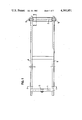
- FIG. 1 shows the arrangement of the load cells in a truck according to a first embodiment of the device according to the invention
- FIG. 2 is a cross section according to the line E--E of FIG. 1,
- FIG. 3 is a cross section according to the line B--B of FIG. 1,
- FIG. 4 shows the setting of the load cells of the device according to the invention
- FIG. 5 shows the set of the load cells within a rectangular coordinate system
- FIG. 6 shows the forces of pressure acting on the load cells
- FIG. 7 shows a schematic view of the tipper and of the truck frame corresponding to a second embodiment of the device according to the invention
- FIG. 8 shows the arrangement of the load cells of the device according to a third embodiment of the invention
- FIG. 9 shows the disposition of the forces and of the lever arms permitting the calculation of the useful load and of the forces on the axles
- FIG. 10 shows the block diagram of the electronic circuit utilized with the device according to the first embodiment of the invention.
- FIG. 11 shows the setting of the front load cells of FIG. 8.
- FIG. 1 shows a view of the frame of a truck in which 1 and 2 indicate respectively a front axle and a rear axle on which are mounted three cylindrical load cells 3, 4 and 5.
- the axle 1 supports the tipper and the axle 2 is the axle about which the tipper may tip.
- the load cells 4 and 5 are mounted symmetrically along the axle 2, their axis coinciding with the latter. The spacing between them is equal to the one of the sections of the truck frame.
- the load cell 3 is mounted in the middle of the front axle supporting the tipper, its axis coniciding with the longitudinal axis of the truck is therefore perpendicular to the axle 1. It is to be seen that in the embodiment of FIG. 1 the front load cell is arranged perpendicularly to the rear load cells 4 and 5.
- FIG. 2 shows a cross section along the line E--E of FIG. 1.
- the truck frame 6 supports an intermediate frame 7 by means of a rectangular ring 8 of resilient material for permitting a certain mobility of the intermediate frame.
- the latter supports the load cells 3, 4 and 5 and it is intended to be built in on already existing vehicles on which the device according to the invention is to be incorporated.
- the frame of the latter may be so designed as to support directly the load cells which eliminates the necessity to provide an intermediate frame.
- the frame 9 of the tipper Above the intermediate frame 7 is disposed the frame 9 of the tipper.
- FIG. 2 shows that the base plate 11 of the tipper lies on a tube 12, e.g.
- FIG. 2 shows further that the lateral extremities of the frame 9 of the tipper do not lie on the intermediate frame 7, being separated from the latter by clearances 13 which allows for a deformation of the tipper permitting a rotation of the latter about the axis of the load cell 3 when the load is placed unsymmetrically in the tipper with respect to the axis of the load cell 3. This permits to prevent undesirable strengthening constraints on the load cell 3.
- the rotation of the tipper about the axle 1 is limited by the width of the clearances 13.
- FIG. 3 shows a cross section along the line B--B of FIG. 1.
- the frame of the tipper bears a section 15 on which are welded a pair of plates 16 leaning on the extremities of the load cell 5 for transmitting to the latter the forces exerted by the weight of the tipper and of the useful load.
- a second pair of plates 16 welded on the section 15 transmits these forces to the load cell 4.
- the plates 16 as well as the plates 10 of FIG. 2 are capable of turning and sliding on the load cells 3, 4 and 5. In the case of a truck with a tilting tipper having an intermediate frame the tilting of the intermediate frame supporting the tipper is ensured by a hydraulic piston acting under the intermediate frame.
- This arrangement has the advantage that the weight of the piston is not measured by the load cells 3, 4 and 5 and that the friction between the tipper and the intermediate frame does not influence the measurement of the weights of the tipper and of the useful load. This prevents every error of the measurement.
- FIG. 4 shows the principle of the setting of the load cells 3, 4 and 5 in the intermediate frame or, as the case may arise, in the truck frame.
- a tube 17 is welded to the intermediate frame 7. Within and in the middle of this tube is pressed in a housing or support of a knee-joint 18.
- the support 18 contains a knee-joint 19 pressed in on the load cell and capable of free turning in the support 18.
- Spacing sleeves 20 placed on either side of the knee-joint 19 and capable of sliding on the load cell permit a certain lateral displacement of the plates 10 and 16 due to the fact that a clearance is provided on the one hand between the outer sides of the sleeves 20 and the inner walls of the plates 10, 16 and on the other hand between the plates 10, 16 and the tube 17 as well as between the plates 10,16 and the intermediate frame 7.
- the load cell is prevented from turning about its axis with respect to the plates 10, 16 by a plaquette 21 fixed to one of the plates 10, 16 and inserted within a groove of the load cell.
- a lateral play is provided between the plaquette 21 and the load cell for permitting the lateral displacement of the plates 10,16 on the load cell.
- the load cell may further rotate about an axis perpendicular to the plane of FIG. 4 and about its axis 1,2 with respect to the intermediate frame 7 or with respect to the truck frame if the load cells are mounted on the latter.
- the tipper has four degrees of freedom. Practically the above mentioned displacements and rotations occur in response to useful loads being not uniformly distributed. at the surface of the tipper and when the truck is tilted, the plane of the tipper being not horizontal. Due to the knee-joint setting of the load cells and to their arrangement according to FIG. 1 the load cells are not submitted to constraints of flexion and torsion. They are submitted only to constraints of pressure P as indicated in FIG. 6. This eliminates the parasitic constraints and contributes to appreciably increase the precision of the measurement because the load cells are submitted only to the constraints resulting from the weights of the tipper and of the useful load. A relatively high precision of the measurement in the order of 1 to 2% as accomplished by the above described system offers to the user the following advantages:
- the useful load being known with a small error margin the fixing of its price corresponds to the weight effectively delivered to the user which eliminates the subjects of contestation relatively to the price to be paid, and
- the useful load being known with precision, this contributes as a general rule to diminish the wear of the vehicle, of the tires and of the brakes as well as to decrease the fuel consumption and the reparations.
- the useful life of the vehicle is augmented.
- FIG. 7 shows in a second embodiment of the device according to the invention an arrangement of the truck frame 22 and of the tipper 23 permitting to dispose the front load cell 3 with its axis parallel to the axle 1 of the truck, that is parallel to the axis of the load cells 4 and 5.
- the tipper 23 In order to give to the tipper the same number of degrees of freedom than in the preceding case it is possible to connect, in the front portion of the truck, the tipper 23 to the frame 22 by an attachment 24 capable of turning about the axles 1 and 1'.
- FIG. 8 shows that the number of load cells is not obligatory limited to three and that within the general meaning of the invention the arrangement of the tipper and of the truck frame permits the utilization of four load cells 3, 3', 4 and 5 when for particular applications it is not possible to utilize only three load cells.
- the front load cells 3 and 3' are disposed with their axis parallel and coinciding with the front axle of the truck.
- the arrangement of FIG. 8 would limit the number of degrees of freedom to three instead of four because the linear displacement of the tipper along the Z-axis of FIG. 5 would not be possible.
- FIG. 11 shows a section through the front load cells 3 or 3', the knee-joint 19', the housing 18' and the tube 17' of the embodiment of FIG. 8.
- the tube 17' has a rectangular section as well as the housing 18'.
- the housing 18' is mounted in the tube 17' by two keys 45 and 46 fixed each in a lit of tube 17' and slidingly engaging within two grooves 47 and 48 of the housing 18'. Clearances 50 are provided on either side of the housing 18'.
- This arrangement permits a displacement of the axle 1 with the load cells 3 and 3' along the Z-axis of FIG. 5 while preventing a displacement of the housing 18' along the axis of the load cells and a vertical displacement of the load cells. Therefore, the arrangement of FIG. 8 comprising four load cells has also four degrees of freedom as in the case of the embodiment of FIG. 1.
- FIG. 9 shows in the case of the embodiment of FIG. 1 the forces acting on the load cells and the disposition of the lever arms for the calculation of the forces A V and A H on the axles of the vehicle.
- the force P 3 acts on the front load cell 3 and the force P 4+5 on the set of the rear load cells 4 and 5.
- the relations (1), (2) and (3) may be calculated by an electronic circuit the diagram of which is the one of FIG. 10. It is assumed that the load cells delivers e.g. a voltage proportional to the forces P exerted.
- FIG. 10 shows that the signal of the load cell 3 is amplified by an operational amplifier 27 and that the sum U 4+5 effected by the summator 25 of the signals of the load cells 4 and 5 is amplified by an operational amplifier 26.
- the summator 32 delivers a signal equal to A+B+tare corresponding to the contribution of the useful load on the rear axle, the summator 33 a signal D-C+tare corresponding to the useful load on the front axle and the summator 34 the sum U 3 +U 4+5 -tare which corresponds to the useful load.
- the commutator 35 permits to connect the display 36 as desired to the outputs of the summators 32 (rear axle), 33 (front axle) and 34 (useful load).
- the electronic comprises limits surveillance circuits 37 to 39 associated respectively to overloading indicators 40 to 42 in order to prevent the user to overload the vehicle.
- the device according to the invention provides a particularly efficient solution to the problem to be solved permitting to attain, more particularly, a high precision of the measurement of the useful load and of the load on the axles of the vehicle.
- the principle of the device according to the present invention may also be applied for three axles vehicles and for trailer cars.
Abstract
Description
P.sub.total =P.sub.3 +P.sub.4+5 (1)
Claims (12)
Applications Claiming Priority (2)
| Application Number | Priority Date | Filing Date | Title |
|---|---|---|---|
| CH9066/80 | 1980-12-09 | ||
| CH906680A CH639609A5 (en) | 1980-12-09 | 1980-12-09 | TRUCK WITH A DEVICE FOR MEASURING THE WORK LOAD AND THE AXLE LOAD OF THE SAME. |
Publications (1)
| Publication Number | Publication Date |
|---|---|
| US4393951A true US4393951A (en) | 1983-07-19 |
Family
ID=4347963
Family Applications (1)
| Application Number | Title | Priority Date | Filing Date |
|---|---|---|---|
| US06/325,647 Expired - Lifetime US4393951A (en) | 1980-12-09 | 1981-11-30 | Measuring device of the useful load and of the load on the axles of a truck |
Country Status (6)
| Country | Link |
|---|---|
| US (1) | US4393951A (en) |
| EP (1) | EP0054000B1 (en) |
| JP (1) | JPS57122323A (en) |
| AT (1) | ATE16529T1 (en) |
| CH (1) | CH639609A5 (en) |
| DE (1) | DE3172927D1 (en) |
Cited By (36)
| Publication number | Priority date | Publication date | Assignee | Title |
|---|---|---|---|---|
| US4630227A (en) * | 1984-04-27 | 1986-12-16 | Hagenbuch Roy George Le | Apparatus and method for on-board measuring of the load carried by a truck body |
| US4714122A (en) * | 1986-10-20 | 1987-12-22 | Breakthru Industries, Inc. | Weighing system for refuse trucks |
| US4839835A (en) * | 1984-04-27 | 1989-06-13 | Hagenbuch Roy George Le | Apparatus and method responsive to the on-board measuring of the load carried by a truck body |
| US5178226A (en) * | 1990-12-21 | 1993-01-12 | Allan Bowman | Load measuring system for refuse trucks |
| US5245137A (en) * | 1990-12-21 | 1993-09-14 | Mobile Computing Corporation | Load measuring system for refuse trucks |
| US5327347A (en) * | 1984-04-27 | 1994-07-05 | Hagenbuch Roy George Le | Apparatus and method responsive to the on-board measuring of haulage parameters of a vehicle |
| US5384436A (en) * | 1993-06-30 | 1995-01-24 | Pritchard; Gary E. | Apparatus and method for electrically weighing bales in a mobile crop baler |
| US5393936A (en) * | 1992-02-12 | 1995-02-28 | Rancan Fertilizer Systems, Inc. | On board weighing system for a vehicle |
| US5416706A (en) * | 1984-04-27 | 1995-05-16 | Hagenbuch; Leroy G. | Apparatus for identifying containers from which refuse is collected and compiling a historical record of the containers |
| GB2304910A (en) * | 1995-09-09 | 1997-03-26 | Massey Ferguson Ltd | Vehicle with continuous sensing of payload weight |
| US5631835A (en) * | 1984-04-27 | 1997-05-20 | Hagenbuch; Leroy G. | Apparatus for identifying containers from which refuse is collected and compiling a historical record of the containers |
| US20060053898A1 (en) * | 2003-03-21 | 2006-03-16 | Bizerba Gmbh & Co. Kg | Dynamometric cell |
| US7658196B2 (en) | 2005-02-24 | 2010-02-09 | Ethicon Endo-Surgery, Inc. | System and method for determining implanted device orientation |
| US7775215B2 (en) | 2005-02-24 | 2010-08-17 | Ethicon Endo-Surgery, Inc. | System and method for determining implanted device positioning and obtaining pressure data |
| US7775966B2 (en) | 2005-02-24 | 2010-08-17 | Ethicon Endo-Surgery, Inc. | Non-invasive pressure measurement in a fluid adjustable restrictive device |
| US7844342B2 (en) | 2008-02-07 | 2010-11-30 | Ethicon Endo-Surgery, Inc. | Powering implantable restriction systems using light |
| US7927270B2 (en) | 2005-02-24 | 2011-04-19 | Ethicon Endo-Surgery, Inc. | External mechanical pressure sensor for gastric band pressure measurements |
| US8016744B2 (en) | 2005-02-24 | 2011-09-13 | Ethicon Endo-Surgery, Inc. | External pressure-based gastric band adjustment system and method |
| US8016745B2 (en) | 2005-02-24 | 2011-09-13 | Ethicon Endo-Surgery, Inc. | Monitoring of a food intake restriction device |
| US8034065B2 (en) | 2008-02-26 | 2011-10-11 | Ethicon Endo-Surgery, Inc. | Controlling pressure in adjustable restriction devices |
| US8057492B2 (en) | 2008-02-12 | 2011-11-15 | Ethicon Endo-Surgery, Inc. | Automatically adjusting band system with MEMS pump |
| US8066629B2 (en) | 2005-02-24 | 2011-11-29 | Ethicon Endo-Surgery, Inc. | Apparatus for adjustment and sensing of gastric band pressure |
| US8100870B2 (en) | 2007-12-14 | 2012-01-24 | Ethicon Endo-Surgery, Inc. | Adjustable height gastric restriction devices and methods |
| US8114345B2 (en) | 2008-02-08 | 2012-02-14 | Ethicon Endo-Surgery, Inc. | System and method of sterilizing an implantable medical device |
| US8142452B2 (en) | 2007-12-27 | 2012-03-27 | Ethicon Endo-Surgery, Inc. | Controlling pressure in adjustable restriction devices |
| US8152710B2 (en) | 2006-04-06 | 2012-04-10 | Ethicon Endo-Surgery, Inc. | Physiological parameter analysis for an implantable restriction device and a data logger |
| US8187163B2 (en) | 2007-12-10 | 2012-05-29 | Ethicon Endo-Surgery, Inc. | Methods for implanting a gastric restriction device |
| US8187162B2 (en) | 2008-03-06 | 2012-05-29 | Ethicon Endo-Surgery, Inc. | Reorientation port |
| US8192350B2 (en) | 2008-01-28 | 2012-06-05 | Ethicon Endo-Surgery, Inc. | Methods and devices for measuring impedance in a gastric restriction system |
| US8221439B2 (en) | 2008-02-07 | 2012-07-17 | Ethicon Endo-Surgery, Inc. | Powering implantable restriction systems using kinetic motion |
| US8233995B2 (en) | 2008-03-06 | 2012-07-31 | Ethicon Endo-Surgery, Inc. | System and method of aligning an implantable antenna |
| US8337389B2 (en) | 2008-01-28 | 2012-12-25 | Ethicon Endo-Surgery, Inc. | Methods and devices for diagnosing performance of a gastric restriction system |
| US8377079B2 (en) | 2007-12-27 | 2013-02-19 | Ethicon Endo-Surgery, Inc. | Constant force mechanisms for regulating restriction devices |
| US8591395B2 (en) | 2008-01-28 | 2013-11-26 | Ethicon Endo-Surgery, Inc. | Gastric restriction device data handling devices and methods |
| US8591532B2 (en) | 2008-02-12 | 2013-11-26 | Ethicon Endo-Sugery, Inc. | Automatically adjusting band system |
| US8870742B2 (en) | 2006-04-06 | 2014-10-28 | Ethicon Endo-Surgery, Inc. | GUI for an implantable restriction device and a data logger |
Families Citing this family (6)
| Publication number | Priority date | Publication date | Assignee | Title |
|---|---|---|---|---|
| SE436181B (en) * | 1983-05-31 | 1984-11-19 | Bengt Olsson | SET FOR DETERMINING THE WEIGHT OF LOADS OF LAST VEHICLES PROVIDED WITH FLAKES TIPABLE AT LEAST TWO GEOMETRICALLY OPPOSITE HALLS |
| GB8815108D0 (en) * | 1988-06-24 | 1988-08-03 | Wood J | Vehicle load weighing means |
| FI84103C (en) * | 1989-11-24 | 1991-10-10 | Tamtron Oy | ARRANGEMANG FOER VAEGNING AV EN LAST. |
| EP0513463A1 (en) * | 1991-05-17 | 1992-11-19 | Padro i Rubi, D. Ferran | Weighing device for use in goods transport vehicles |
| DE19931381A1 (en) * | 1999-07-07 | 2001-01-11 | Hbm Waegetechnik Gmbh | Weighing device for weighing goods on vehicles |
| NL1018289C2 (en) * | 2001-06-14 | 2002-04-08 | Geesink Bv | Refuse collection vehicle with weighing cells, has superstructure load on cells directed along chassis bar neutral axes |
Citations (11)
| Publication number | Priority date | Publication date | Assignee | Title |
|---|---|---|---|---|
| US3037380A (en) * | 1958-10-15 | 1962-06-05 | Allegany Instr Company Inc | Force measuring instrument |
| US3146839A (en) * | 1963-03-05 | 1964-09-01 | Bernard E Carlson | Electronic load indicating device for vehicles with floating body mounting |
| US3279550A (en) * | 1963-12-23 | 1966-10-18 | Donald J Kersten | Truck load measuring system |
| US3603418A (en) * | 1969-10-17 | 1971-09-07 | Gen Trailer Co Inc | Vehicle load measuring apparatus |
| FR2143404A1 (en) * | 1971-06-24 | 1973-02-02 | Malmgrens Mek Verkstad | |
| US3971451A (en) * | 1974-10-01 | 1976-07-27 | Carl Eric Bertil Norberg | Method and apparatus for indicating a load placed on a load-carrying vehicle platform |
| US3999621A (en) * | 1974-12-18 | 1976-12-28 | Howe Richardson Scale Company | Low profile platform weighing scale |
| US4020911A (en) * | 1973-08-10 | 1977-05-03 | Structural Instrumentation, Inc. | Load cell scale |
| US4042049A (en) * | 1975-09-29 | 1977-08-16 | Structural Instrumentation, Inc. | Vehicle load measuring system |
| US4062415A (en) * | 1976-10-20 | 1977-12-13 | Koppers Company, Inc. | Method for weighing a vessel supported by shafts journaled in pressurized bearings |
| US4095660A (en) * | 1975-09-18 | 1978-06-20 | Kurt Eilert Johansson | Roller |
Family Cites Families (5)
| Publication number | Priority date | Publication date | Assignee | Title |
|---|---|---|---|---|
| GB991616A (en) * | 1961-07-25 | 1965-05-12 | Kins Developments Ltd | Improvements in and relating to weighing apparatus |
| GB1310889A (en) * | 1969-12-04 | 1973-03-21 | Rich P W | Electrical measuring device |
| DE2442624A1 (en) * | 1973-11-02 | 1975-05-07 | Saunders Transport Ltd | WEIGHING DEVICE FOR TRUCKS |
| US3927724A (en) * | 1975-02-26 | 1975-12-23 | Royal Industries | Load cell retaining apparatus for on-board vehicle weighing systems |
| DE2522105C2 (en) * | 1975-05-17 | 1983-09-15 | Knorr-Bremse GmbH, 8000 München | Arrangement for determining the axle load on two-axle rail vehicles |
-
1980
- 1980-12-09 CH CH906680A patent/CH639609A5/en not_active IP Right Cessation
-
1981
- 1981-11-30 EP EP81810473A patent/EP0054000B1/en not_active Expired
- 1981-11-30 US US06/325,647 patent/US4393951A/en not_active Expired - Lifetime
- 1981-11-30 DE DE8181810473T patent/DE3172927D1/en not_active Expired
- 1981-11-30 AT AT81810473T patent/ATE16529T1/en not_active IP Right Cessation
- 1981-12-08 JP JP56197597A patent/JPS57122323A/en active Pending
Patent Citations (12)
| Publication number | Priority date | Publication date | Assignee | Title |
|---|---|---|---|---|
| US3037380A (en) * | 1958-10-15 | 1962-06-05 | Allegany Instr Company Inc | Force measuring instrument |
| US3146839A (en) * | 1963-03-05 | 1964-09-01 | Bernard E Carlson | Electronic load indicating device for vehicles with floating body mounting |
| US3279550A (en) * | 1963-12-23 | 1966-10-18 | Donald J Kersten | Truck load measuring system |
| US3603418A (en) * | 1969-10-17 | 1971-09-07 | Gen Trailer Co Inc | Vehicle load measuring apparatus |
| FR2143404A1 (en) * | 1971-06-24 | 1973-02-02 | Malmgrens Mek Verkstad | |
| US4020911A (en) * | 1973-08-10 | 1977-05-03 | Structural Instrumentation, Inc. | Load cell scale |
| US3971451A (en) * | 1974-10-01 | 1976-07-27 | Carl Eric Bertil Norberg | Method and apparatus for indicating a load placed on a load-carrying vehicle platform |
| US3999621A (en) * | 1974-12-18 | 1976-12-28 | Howe Richardson Scale Company | Low profile platform weighing scale |
| US4095660A (en) * | 1975-09-18 | 1978-06-20 | Kurt Eilert Johansson | Roller |
| US4042049A (en) * | 1975-09-29 | 1977-08-16 | Structural Instrumentation, Inc. | Vehicle load measuring system |
| US4102031A (en) * | 1975-09-29 | 1978-07-25 | Structural Instrumentation, Inc. | Method of installing a transducer on a structural member |
| US4062415A (en) * | 1976-10-20 | 1977-12-13 | Koppers Company, Inc. | Method for weighing a vessel supported by shafts journaled in pressurized bearings |
Cited By (46)
| Publication number | Priority date | Publication date | Assignee | Title |
|---|---|---|---|---|
| US5650928A (en) * | 1984-04-27 | 1997-07-22 | Hagenbuch; Leroy G. | Apparatus and method responsive to the on-board measuring of haulage parameters of a vehicle |
| US5742914A (en) * | 1984-04-27 | 1998-04-21 | Hagenbuch; Leroy G. | Apparatus and method responsive to the on-board measuring of haulage parameters of a vehicle |
| US5631835A (en) * | 1984-04-27 | 1997-05-20 | Hagenbuch; Leroy G. | Apparatus for identifying containers from which refuse is collected and compiling a historical record of the containers |
| US5995888A (en) * | 1984-04-27 | 1999-11-30 | Hagenbuch; Leroy G. | Apparatus and method responsive to the on-board measuring of haulage parameters of a vehicle |
| US4630227A (en) * | 1984-04-27 | 1986-12-16 | Hagenbuch Roy George Le | Apparatus and method for on-board measuring of the load carried by a truck body |
| US5327347A (en) * | 1984-04-27 | 1994-07-05 | Hagenbuch Roy George Le | Apparatus and method responsive to the on-board measuring of haulage parameters of a vehicle |
| US5650930A (en) * | 1984-04-27 | 1997-07-22 | Hagenbuch; Leroy G. | Apparatus and method responsive to the on-board measuring of haulage parameters of a vehicle |
| US5644489A (en) * | 1984-04-27 | 1997-07-01 | Hagenbuch; Leroy G. | Apparatus and method for identifying containers from which material is collected and loaded onto a haulage vehicle |
| US5631832A (en) * | 1984-04-27 | 1997-05-20 | Hagenbuch; Leroy G. | Apparatus and method responsive to the on-board measuring of haulage parameters of a vehicle |
| US5528499A (en) * | 1984-04-27 | 1996-06-18 | Hagenbuch; Leroy G. | Apparatus and method responsive to the on-board measuring of haulage parameters of a vehicle |
| US5416706A (en) * | 1984-04-27 | 1995-05-16 | Hagenbuch; Leroy G. | Apparatus for identifying containers from which refuse is collected and compiling a historical record of the containers |
| US4839835A (en) * | 1984-04-27 | 1989-06-13 | Hagenbuch Roy George Le | Apparatus and method responsive to the on-board measuring of the load carried by a truck body |
| US4714122A (en) * | 1986-10-20 | 1987-12-22 | Breakthru Industries, Inc. | Weighing system for refuse trucks |
| US5245137A (en) * | 1990-12-21 | 1993-09-14 | Mobile Computing Corporation | Load measuring system for refuse trucks |
| US5178226A (en) * | 1990-12-21 | 1993-01-12 | Allan Bowman | Load measuring system for refuse trucks |
| US5393936A (en) * | 1992-02-12 | 1995-02-28 | Rancan Fertilizer Systems, Inc. | On board weighing system for a vehicle |
| US5384436A (en) * | 1993-06-30 | 1995-01-24 | Pritchard; Gary E. | Apparatus and method for electrically weighing bales in a mobile crop baler |
| GB2304910B (en) * | 1995-09-09 | 1999-06-23 | Massey Ferguson Ltd | Vehicle with weight sensing |
| US6150617A (en) * | 1995-09-09 | 2000-11-21 | Agco Limited | Vehicle with weight sensing |
| GB2304910A (en) * | 1995-09-09 | 1997-03-26 | Massey Ferguson Ltd | Vehicle with continuous sensing of payload weight |
| US7380475B2 (en) | 2003-03-21 | 2008-06-03 | Bizerba Gmbh & Co. Kg | Dynamometric cell |
| US20060053898A1 (en) * | 2003-03-21 | 2006-03-16 | Bizerba Gmbh & Co. Kg | Dynamometric cell |
| US7658196B2 (en) | 2005-02-24 | 2010-02-09 | Ethicon Endo-Surgery, Inc. | System and method for determining implanted device orientation |
| US7775966B2 (en) | 2005-02-24 | 2010-08-17 | Ethicon Endo-Surgery, Inc. | Non-invasive pressure measurement in a fluid adjustable restrictive device |
| US7927270B2 (en) | 2005-02-24 | 2011-04-19 | Ethicon Endo-Surgery, Inc. | External mechanical pressure sensor for gastric band pressure measurements |
| US8016744B2 (en) | 2005-02-24 | 2011-09-13 | Ethicon Endo-Surgery, Inc. | External pressure-based gastric band adjustment system and method |
| US8016745B2 (en) | 2005-02-24 | 2011-09-13 | Ethicon Endo-Surgery, Inc. | Monitoring of a food intake restriction device |
| US7775215B2 (en) | 2005-02-24 | 2010-08-17 | Ethicon Endo-Surgery, Inc. | System and method for determining implanted device positioning and obtaining pressure data |
| US8066629B2 (en) | 2005-02-24 | 2011-11-29 | Ethicon Endo-Surgery, Inc. | Apparatus for adjustment and sensing of gastric band pressure |
| US8152710B2 (en) | 2006-04-06 | 2012-04-10 | Ethicon Endo-Surgery, Inc. | Physiological parameter analysis for an implantable restriction device and a data logger |
| US8870742B2 (en) | 2006-04-06 | 2014-10-28 | Ethicon Endo-Surgery, Inc. | GUI for an implantable restriction device and a data logger |
| US8187163B2 (en) | 2007-12-10 | 2012-05-29 | Ethicon Endo-Surgery, Inc. | Methods for implanting a gastric restriction device |
| US8100870B2 (en) | 2007-12-14 | 2012-01-24 | Ethicon Endo-Surgery, Inc. | Adjustable height gastric restriction devices and methods |
| US8377079B2 (en) | 2007-12-27 | 2013-02-19 | Ethicon Endo-Surgery, Inc. | Constant force mechanisms for regulating restriction devices |
| US8142452B2 (en) | 2007-12-27 | 2012-03-27 | Ethicon Endo-Surgery, Inc. | Controlling pressure in adjustable restriction devices |
| US8192350B2 (en) | 2008-01-28 | 2012-06-05 | Ethicon Endo-Surgery, Inc. | Methods and devices for measuring impedance in a gastric restriction system |
| US8337389B2 (en) | 2008-01-28 | 2012-12-25 | Ethicon Endo-Surgery, Inc. | Methods and devices for diagnosing performance of a gastric restriction system |
| US8591395B2 (en) | 2008-01-28 | 2013-11-26 | Ethicon Endo-Surgery, Inc. | Gastric restriction device data handling devices and methods |
| US8221439B2 (en) | 2008-02-07 | 2012-07-17 | Ethicon Endo-Surgery, Inc. | Powering implantable restriction systems using kinetic motion |
| US7844342B2 (en) | 2008-02-07 | 2010-11-30 | Ethicon Endo-Surgery, Inc. | Powering implantable restriction systems using light |
| US8114345B2 (en) | 2008-02-08 | 2012-02-14 | Ethicon Endo-Surgery, Inc. | System and method of sterilizing an implantable medical device |
| US8057492B2 (en) | 2008-02-12 | 2011-11-15 | Ethicon Endo-Surgery, Inc. | Automatically adjusting band system with MEMS pump |
| US8591532B2 (en) | 2008-02-12 | 2013-11-26 | Ethicon Endo-Sugery, Inc. | Automatically adjusting band system |
| US8034065B2 (en) | 2008-02-26 | 2011-10-11 | Ethicon Endo-Surgery, Inc. | Controlling pressure in adjustable restriction devices |
| US8187162B2 (en) | 2008-03-06 | 2012-05-29 | Ethicon Endo-Surgery, Inc. | Reorientation port |
| US8233995B2 (en) | 2008-03-06 | 2012-07-31 | Ethicon Endo-Surgery, Inc. | System and method of aligning an implantable antenna |
Also Published As
| Publication number | Publication date |
|---|---|
| EP0054000B1 (en) | 1985-11-13 |
| ATE16529T1 (en) | 1985-11-15 |
| JPS57122323A (en) | 1982-07-30 |
| EP0054000A1 (en) | 1982-06-16 |
| DE3172927D1 (en) | 1985-12-19 |
| CH639609A5 (en) | 1983-11-30 |
Similar Documents
| Publication | Publication Date | Title |
|---|---|---|
| US4393951A (en) | Measuring device of the useful load and of the load on the axles of a truck | |
| US4042049A (en) | Vehicle load measuring system | |
| US3658143A (en) | Flexure plate scale with hydraulic load cell | |
| US5880409A (en) | Onboard weighing system for truck having single point suspension | |
| US3800895A (en) | Vehicle weighing device with a balanced electrical bridge | |
| US4575254A (en) | Transit mixer support pedestal mounting apparatus | |
| US5511812A (en) | Fifth wheel coupling | |
| US4813504A (en) | Load cell structure | |
| US3283838A (en) | Apparatus and method for computing equivalent weight of tractor trailer vehicle | |
| CA1061814A (en) | Leaf spring weighing scale | |
| US4884644A (en) | Vehicle on-board transducer for use with dual axle equalizer hanger systems | |
| US4714121A (en) | Wheel scale assembly | |
| CN214096307U (en) | Split type movable vehicle weighing wagon balance | |
| EP1111353B1 (en) | Weighing device | |
| US5526702A (en) | Arrangement of measuring devices on a semitrailer motor vehicle | |
| US20080211198A1 (en) | Load Sensing Wheel Support Knuckle Assembly and Method for Use | |
| CN113066297A (en) | Semi-trailer vehicle-mounted weighing system suitable for main and auxiliary leaf springs | |
| US20220074785A1 (en) | Method for monitoring a load carrier vehicle, monitoring device for a load carrier vehicle, load carrier vehicle, load carrier vehicle system and swap body | |
| GB2122748A (en) | Vehicle axle load measuring device | |
| JP3209136B2 (en) | Semi-trailer load measuring device | |
| JP2565357B2 (en) | Vehicle weight measuring device | |
| JPH01172711A (en) | Weight measuring apparatus for vehicle | |
| RU2037789C1 (en) | Weighing equipment | |
| JP2591665Y2 (en) | Vehicle load measuring device | |
| GB1499300A (en) | Axle load measuring device for vehicles |
Legal Events
| Date | Code | Title | Description |
|---|---|---|---|
| AS | Assignment |
Owner name: VIBRO-METER S.A. 4, ROUTE DE MONCOR 1700 FRIBOURG, Free format text: ASSIGNMENT OF ASSIGNORS INTEREST.;ASSIGNORS:HORST-RUDOLF, LOOS;BERNARD, DUPRE;REEL/FRAME:003955/0557 Effective date: 19811117 Owner name: VIBRO-METER S.A., SWITZERLAND Free format text: ASSIGNMENT OF ASSIGNORS INTEREST;ASSIGNORS:HORST-RUDOLF, LOOS;BERNARD, DUPRE;REEL/FRAME:003955/0557 Effective date: 19811117 |
|
| STCF | Information on status: patent grant |
Free format text: PATENTED CASE |
|
| MAFP | Maintenance fee payment |
Free format text: PAYMENT OF MAINTENANCE FEE, 4TH YEAR, PL 96-517 (ORIGINAL EVENT CODE: M170); ENTITY STATUS OF PATENT OWNER: LARGE ENTITY Year of fee payment: 4 |
|
| MAFP | Maintenance fee payment |
Free format text: PAYMENT OF MAINTENANCE FEE, 8TH YEAR, PL 96-517 (ORIGINAL EVENT CODE: M171); ENTITY STATUS OF PATENT OWNER: LARGE ENTITY Year of fee payment: 8 |
|
| MAFP | Maintenance fee payment |
Free format text: PAYMENT OF MAINTENANCE FEE, 12TH YEAR, LARGE ENTITY (ORIGINAL EVENT CODE: M185); ENTITY STATUS OF PATENT OWNER: LARGE ENTITY Year of fee payment: 12 |
|
| FEPP | Fee payment procedure |
Free format text: PAT HLDR NO LONGER CLAIMS SMALL ENT STAT AS INDIV INVENTOR (ORIGINAL EVENT CODE: LSM1); ENTITY STATUS OF PATENT OWNER: LARGE ENTITY |