US4386756A - Self centering floating metal seal for a ball valve - Google Patents
Self centering floating metal seal for a ball valve Download PDFInfo
- Publication number
- US4386756A US4386756A US06/222,738 US22273881A US4386756A US 4386756 A US4386756 A US 4386756A US 22273881 A US22273881 A US 22273881A US 4386756 A US4386756 A US 4386756A
- Authority
- US
- United States
- Prior art keywords
- valve member
- valve
- spherical
- bore
- valve body
- Prior art date
- Legal status (The legal status is an assumption and is not a legal conclusion. Google has not performed a legal analysis and makes no representation as to the accuracy of the status listed.)
- Expired - Lifetime
Links
Images


Classifications
-
- F—MECHANICAL ENGINEERING; LIGHTING; HEATING; WEAPONS; BLASTING
- F16—ENGINEERING ELEMENTS AND UNITS; GENERAL MEASURES FOR PRODUCING AND MAINTAINING EFFECTIVE FUNCTIONING OF MACHINES OR INSTALLATIONS; THERMAL INSULATION IN GENERAL
- F16K—VALVES; TAPS; COCKS; ACTUATING-FLOATS; DEVICES FOR VENTING OR AERATING
- F16K5/00—Plug valves; Taps or cocks comprising only cut-off apparatus having at least one of the sealing faces shaped as a more or less complete surface of a solid of revolution, the opening and closing movement being predominantly rotary
- F16K5/06—Plug valves; Taps or cocks comprising only cut-off apparatus having at least one of the sealing faces shaped as a more or less complete surface of a solid of revolution, the opening and closing movement being predominantly rotary with plugs having spherical surfaces; Packings therefor
- F16K5/0663—Packings
- F16K5/0673—Composite packings
-
- F—MECHANICAL ENGINEERING; LIGHTING; HEATING; WEAPONS; BLASTING
- F16—ENGINEERING ELEMENTS AND UNITS; GENERAL MEASURES FOR PRODUCING AND MAINTAINING EFFECTIVE FUNCTIONING OF MACHINES OR INSTALLATIONS; THERMAL INSULATION IN GENERAL
- F16K—VALVES; TAPS; COCKS; ACTUATING-FLOATS; DEVICES FOR VENTING OR AERATING
- F16K5/00—Plug valves; Taps or cocks comprising only cut-off apparatus having at least one of the sealing faces shaped as a more or less complete surface of a solid of revolution, the opening and closing movement being predominantly rotary
- F16K5/06—Plug valves; Taps or cocks comprising only cut-off apparatus having at least one of the sealing faces shaped as a more or less complete surface of a solid of revolution, the opening and closing movement being predominantly rotary with plugs having spherical surfaces; Packings therefor
- F16K5/0647—Spindles or actuating means
-
- F—MECHANICAL ENGINEERING; LIGHTING; HEATING; WEAPONS; BLASTING
- F16—ENGINEERING ELEMENTS AND UNITS; GENERAL MEASURES FOR PRODUCING AND MAINTAINING EFFECTIVE FUNCTIONING OF MACHINES OR INSTALLATIONS; THERMAL INSULATION IN GENERAL
- F16K—VALVES; TAPS; COCKS; ACTUATING-FLOATS; DEVICES FOR VENTING OR AERATING
- F16K5/00—Plug valves; Taps or cocks comprising only cut-off apparatus having at least one of the sealing faces shaped as a more or less complete surface of a solid of revolution, the opening and closing movement being predominantly rotary
- F16K5/06—Plug valves; Taps or cocks comprising only cut-off apparatus having at least one of the sealing faces shaped as a more or less complete surface of a solid of revolution, the opening and closing movement being predominantly rotary with plugs having spherical surfaces; Packings therefor
- F16K5/0663—Packings
- F16K5/0668—Single packings
Definitions
- the present invention relates to a trunnion-mounted ball valve and more particularly to a trunnion-mounted ball valve which has a pair of self-centering, floating metal seals.
- U.S. Pat. No. 3,269,692 entitled Ball Valve Construction, issued to Homer J. Shafer on Aug. 30, 1966 teaches an improvement for use in a trunnion-mounted ball valve having a housing forming a cavity laterally around the ball and flow tubes longitudinally of the valve, seating rings adjustable longitudinally between the ball and the flow tubes, and resilient seals between the seating rings and the ball.
- the improvement includes a device for utilizing the cavity pressure to force the seating ring on the downstream side of the ball to seal against the ball radially outwardly of the resilient seal.
- the device is a seating ring construction having a greater area exposed to cavity pressure acting toward the ball than its area exposed to cavity pressure acting away from the ball.
- U.S. Pat. No. 3,269,691 entitled Ball Valve Seal Support, issued to Robert J. Meima and James D. Aiken on Aug. 30, 1966 teaches an improvement for a valve which includes a casing having a central bore terminating in shoulders defining axially outer reduced bores which terminate in shoulders defining inlet and outlet ports communicating with the bores; a ball including a flow passage rotatably mounted in the central bore and valve seats slidably and rotatably mounted in the reduced bores and having enlarged portions terminating in shoulders.
- the valve also includes a ball engaging valve seal slidably mounted on each of the portions.
- valve seats and the portions containing the seals are movable from an operative ball engaging position to a ball clearance position against the bore and port defining shoulders.
- pins fixed to the casing and projecting into the slots to effect axial movement of the seats between the positions upon rotation of the seats.
- a spring acts between the enlarged portion shoulders and the seals to urge the seals against the ball in operative position.
- the valve casing includes a removable cover for the insertion of the ball, a recess formed in the outer peripheries of the valve seats, and retaining pins projecting from the cover and into the recesses to limit the movement of the valve seats toward the ball to limit the pressure of the seals against the ball and retain the valve seats in operative position.
- U.S. Pat. No. 3,226,080 entitled Ball Valve Seat, issued to William E. Lowry on Dec. 28, 1965, teaches a rotatable plug valve that includes a valve body that has a bore extending therethrough, a spherical valve member that is positioned in the bore and that has a port the axis of which is alignable with the axis of the bore in the open position of the valve and an aperture in the valve body.
- the rotatable plug valve also includes a stem that has an inner end which is engaged with the valve member and an axially outer end which extends through the aperture in the valve body and a device for forming a seal between the aperture and the stem.
- the rotatable plug valve further includes detachably connected end members which extend into each end of the bore in the valve body with each end member having a device which limits entry of the end member into the valve body a predetermined amount and with each end member also having a passage with which the port in the valve member can be aligned to form the run of the valve and an axially inner end having a portion taperingly diverging axially outward from the passage.
- the rotatable plug valve still further includes an annular groove in the taperingly diverging portion of the axial inner end with each annular groove having an inner and outer cylindrical walls which are disposed in coaxial relation with the respective passage and also having an end wall which is disposed in substantially normal relation with the cylindrical walls.
- each seat member is positioned in each of the grooves with each seat member being of lesser radial thickness than the radial thickness of its groove so that in the uncompressed condition there is substantial clearance between the seat member and groove along the entire length of both the inner and outer circumferences of the groove.
- Each seat member has a portion which extends beyond the surface of the taperingly diverging portion terminating in a tapered surface to oppose the spherical surface of the valve member with each end member extending into the body bore an amount sufficient to force the seat member into intimate sealing contact with the spherical surface of the valve member upon assembly thereby deforming the seat member a limited amount so that the seat members do not completely fill the groove either during assembly or operation within rated pressure whereby the seat members act as a columnar spring against the spherical valve member.
- the inventor has considered eliminating the resilient, deformable seal between the sealing ring and the ball.
- the difficulty with eliminating the resilient, deformable seal is that the ball valve will leak unless the sealing ring is in perfect contact with the ball. It is impossible to realize perfect contact between the ball and the sealing rings as long as the sealing ring can only move along the axis of the bore of the valve body.
- the primary object of the present invention to provide a ball valve that has a self-centering, floating metal seal.
- the ball valve includes a valve body which has a bore extending therethrough and which also has an inlet and an outlet which are axially aligned and adapted to be mechanically coupled to the conduit.
- the valve body also has an aperture therein.
- the ball valve also includes a spherical valve member having a port the axis of which is alignable with the axis of the bore of the valve body and a stem having an inner end mechanically coupled to the spherical valve member and an axially outer end which extends through the aperture of the valve body.
- the ball valve further includes a device for forming a seal between the aperture of the valve body and the stem.
- the improved self-centering, floating metal seal includes a metal ring which has a planar surface and a contoured surface which is adapted to contact the spherical surface of the valve member and which is axially aligned with the bore of the valve body and is disposed adjacent to the spherical valve member.
- the seal also includes a metal piston which has a first planar surface which is disposed adjacent to the planar surface of the metal ring and a second planar surface. There is a difference in the dynamic sealing areas of the piston and metal ring so that the upstream pressure mechanically seals the ball valve.
- FIG. 1 is a plan view of a ball valve which has a self-centering, floating metal seal in accordance with the principles of the present invention.
- FIG. 2 is a cross-sectional, transverse view of the ball valve of FIG. 1, taken along line 2--2 of FIG. 1 in the open position.
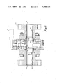
- FIG. 3 is a cross-sectional, transverse view of the ball valve of FIG. 1 in the closed position.
- FIG. 4 is a partial, cross-sectional view of the ball valve of FIG. 1 which shows a portion of the ball valve member and the floating metal seal of the ball valve taken along line 4--4 of FIG. 2.
- FIG. 1 is a plan view of a ball valve that is basically similar to the ball valve taught in U.S. Pat. No. 3,226,080 in that the ball valve includes a valve body 11 having an inlet 12 and an outlet 13 which are axially aligned and which are adapted to be mechanically coupled to a conduit.
- the valve body 11 also has an aperture 14 therethrough.
- the ball valve also includes a bore 15 extending through the valve body 11, a spherical valve member 16 having a port, the axis of which is alignable with the axis of the bore 15 of the valve body 11 and a stem 17 which has an inner end 18 mechanically coupled to the spherical valve member 16 and an axially outer end 19 which extends through the aperture 14 of the valve body 11.
- the ball valve further includes a pair of resilient seals 20 which seal the stem 17 within the aperture 14 and a handle 21 which is mechanically coupled to the axially outer end 19 of the stem 17.
- the ball valve still further includes an improved self-centering, floating metal seal 30 which includes a metal ring 31 having a planar surface and a contoured surface which is adapted to contact the spherical surface of the spherical valve member 16 and a metal piston 32 which has a first planar surface which is disposed adjacent to the planar surface of the metal ring 31 and a second planar surface.
- the spherical member 16 has a port, the axis of which is alignable with the axis of the bore 15 of the valve body 11 and it is mounted on a trunnion 33.
- the bore 15 of the valve body 11 extends therethrough in axial alignment with the inlet 12 and the outlet 13 thereof.
- the self-centering, floating metal seal 30 also includes a pair of resilient sealing devices 34 for forming a seal between the aperture 14 and the bore 15 of the valve body 11.
- the metal piston 32 has a difference in its dynamic sealing areas such that the upstream pressure mechanically sets the ball valve.
- the downstream pressure may mechanically seal the ball valve in that a piston moves in a direction toward larger dynamic sealing area.
- the ball valve is shown in the closed position the upstream pressure acts on the dynamic sealing areas A 1 and A 2 , of the metal piston 32 which are designated in this figure.
- the metal piston 32 reacts in the direction of net difference thereof driving the metal ring 31 into the spherical valve member 16.
- the metal ring 31 contacts the spherical surface of the spherical valve member 16 directly.
- the metal ring 31 is not only able to align itself on the spherical valve member 16, but is also able to scrape off scale and other abrasive deposits that accumulate on the spherical valve member 16 without itself being filed away. This increases the useful service life of the ball valve.
- the metal ring 31 is able to align itself on the spherical valve member 16 because it is not mechanically coupled to the metal piston 32 thereby allowing it to move on the spherical surface of the spherical valve member 16 until it contacts the spherical surface thereof completely along its sealing periphery.
- the self-centering, floating metal seal 30 further includes a resilient seal 35 between the metal ring 31 and the metal piston 32.
- FIG. 4 a self-centering, floating metal seal 30 is shown in an enlarged, partial cross-sectional view.
- the metal seal not only is self-centering because it is not rigidly coupled to the metal piston through which the upstream pressure acts thereon, but also resists erosion which occurs to the other self-centering seals which rely on a resilient, deformable seal in order to overcome misalignment of the spherical valve member and the self-centering seal.
Abstract
Description
Claims (3)
Priority Applications (1)
| Application Number | Priority Date | Filing Date | Title |
|---|---|---|---|
| US06/222,738 US4386756A (en) | 1980-03-27 | 1981-01-05 | Self centering floating metal seal for a ball valve |
Applications Claiming Priority (2)
| Application Number | Priority Date | Filing Date | Title |
|---|---|---|---|
| US13466080A | 1980-03-27 | 1980-03-27 | |
| US06/222,738 US4386756A (en) | 1980-03-27 | 1981-01-05 | Self centering floating metal seal for a ball valve |
Related Parent Applications (1)
| Application Number | Title | Priority Date | Filing Date |
|---|---|---|---|
| US13466080A Continuation | 1980-03-27 | 1980-03-27 |
Publications (1)
| Publication Number | Publication Date |
|---|---|
| US4386756A true US4386756A (en) | 1983-06-07 |
Family
ID=26832550
Family Applications (1)
| Application Number | Title | Priority Date | Filing Date |
|---|---|---|---|
| US06/222,738 Expired - Lifetime US4386756A (en) | 1980-03-27 | 1981-01-05 | Self centering floating metal seal for a ball valve |
Country Status (1)
| Country | Link |
|---|---|
| US (1) | US4386756A (en) |
Cited By (32)
| Publication number | Priority date | Publication date | Assignee | Title |
|---|---|---|---|---|
| US4519412A (en) * | 1983-06-01 | 1985-05-28 | Cameron Iron Works, Inc. | Valve and seal therefor |
| US4548237A (en) * | 1983-12-14 | 1985-10-22 | General Signal Corporation | Ball valve with improved vent structure |
| US4815700A (en) * | 1988-03-24 | 1989-03-28 | Mohrfeld James W | Ball valve with improved seals |
| US5131623A (en) * | 1991-02-25 | 1992-07-21 | Taco, Inc. | Actuator and zone valve |
| US5174546A (en) * | 1991-02-25 | 1992-12-29 | Taco, Inc. | Actuator and zone valve |
| US5746417A (en) * | 1995-02-16 | 1998-05-05 | The Duriron Company, Inc. | Adjustable ball valve |
| US5816283A (en) * | 1997-04-01 | 1998-10-06 | Appalachian Controls Environmental | Tank blanketing system |
| US6482181B1 (en) | 1997-05-28 | 2002-11-19 | Tyco Healthcare Group Lp | Trocar seal system |
| US6551282B1 (en) | 1998-02-23 | 2003-04-22 | Tyco Healthcare Group Lp | Universal seal for use with endoscopic cannula |
| US6595946B1 (en) | 2000-02-25 | 2003-07-22 | United States Surgical Corporation | Valve assembly |
| US6695285B1 (en) | 1999-11-23 | 2004-02-24 | Swagelok Company | Ball valve seat seal |
| US6698712B2 (en) | 2002-05-02 | 2004-03-02 | Dril-Quip, Inc. | Ball valve assembly |
| US6702787B2 (en) | 1997-05-02 | 2004-03-09 | Tyco Healthcare Group Lp | Trocar seal system |
| US6755825B2 (en) | 1998-09-23 | 2004-06-29 | Sherwood Services Ag | Electrosurgical device having a dielectric seal |
| US20040204682A1 (en) * | 2000-11-06 | 2004-10-14 | Smith Robert C. | Surgical sealing apparatus |
| US20050212221A1 (en) * | 2002-05-10 | 2005-09-29 | Smith Robert C | Introducer seal assembly |
| US20060065314A1 (en) * | 2004-09-28 | 2006-03-30 | Allan Bazin | Pigging ball valve |
| US20060224120A1 (en) * | 2005-04-05 | 2006-10-05 | Smith Robert C | Introducer seal assembly with low profile gimbal seal |
| US7195225B1 (en) | 2003-10-30 | 2007-03-27 | Dril-Quip, Inc. | Rotary valve assembly |
| US20090095931A1 (en) * | 2007-10-15 | 2009-04-16 | Stunkard Gerald A | Ball valve having self-centering seats |
| US20090259185A1 (en) * | 2008-04-15 | 2009-10-15 | Tyco Healthcare Group Lp | Self-conforming surgical seal |
| US20100229962A1 (en) * | 2009-03-16 | 2010-09-16 | Robert Anthony Frenzel | Multi-component Metal Seat Design for Ball Valves |
| US20100249708A1 (en) * | 2009-03-26 | 2010-09-30 | Tyco Healthcare Group Lp | Articulating surgical portal apparatus with spring |
| US20110133109A1 (en) * | 2009-12-07 | 2011-06-09 | Cameron International Coporation | Self-relieving ball valve seat |
| US8016824B2 (en) | 2002-07-25 | 2011-09-13 | Covidien Ag | Electrosurgical pencil with drag sensing capability |
| US20120167987A1 (en) * | 2011-01-03 | 2012-07-05 | Cameron International Corporation | Trunnion ball valve seat with v-section spring |
| US8460289B2 (en) | 2005-06-28 | 2013-06-11 | Covidien Ag | Electrode with rotatably deployable sheath |
| US8646752B2 (en) | 2011-02-24 | 2014-02-11 | Virgo Engineers, Inc. | Ball valve having multiple moveable seats |
| US20150102251A1 (en) * | 2013-10-15 | 2015-04-16 | Fisher Controls International Llc | Floating ball valve seal |
| US20180354005A1 (en) * | 2017-06-13 | 2018-12-13 | Mogas Industries, Inc. | Vortex flush ball valve and method |
| US10539242B2 (en) | 2011-01-03 | 2020-01-21 | Cameron International Corporation | Trunnion ball valve with interchangeable and replaceable seat insert |
| CN112824824A (en) * | 2019-11-21 | 2021-05-21 | 重庆红江机械有限责任公司 | Floating self-centering inner diameter measuring device with collision protection |
Citations (5)
| Publication number | Priority date | Publication date | Assignee | Title |
|---|---|---|---|---|
| US3154094A (en) * | 1961-10-25 | 1964-10-27 | Crane Co | Ball valve |
| US3164362A (en) * | 1960-10-07 | 1965-01-05 | Gen Dynamics Corp | Trunnion mounted ball valves having spring biased seats |
| US3508736A (en) * | 1967-05-24 | 1970-04-28 | Rockwell Mfg Co | Seat ring assemblies for valves |
| US3732885A (en) * | 1971-09-29 | 1973-05-15 | H Allen | Valve and method of assembling same |
| US4099705A (en) * | 1976-08-19 | 1978-07-11 | Celanese Corporation | End entry ball valve with seal wear compensation and force isolated seal |
-
1981
- 1981-01-05 US US06/222,738 patent/US4386756A/en not_active Expired - Lifetime
Patent Citations (5)
| Publication number | Priority date | Publication date | Assignee | Title |
|---|---|---|---|---|
| US3164362A (en) * | 1960-10-07 | 1965-01-05 | Gen Dynamics Corp | Trunnion mounted ball valves having spring biased seats |
| US3154094A (en) * | 1961-10-25 | 1964-10-27 | Crane Co | Ball valve |
| US3508736A (en) * | 1967-05-24 | 1970-04-28 | Rockwell Mfg Co | Seat ring assemblies for valves |
| US3732885A (en) * | 1971-09-29 | 1973-05-15 | H Allen | Valve and method of assembling same |
| US4099705A (en) * | 1976-08-19 | 1978-07-11 | Celanese Corporation | End entry ball valve with seal wear compensation and force isolated seal |
Cited By (78)
| Publication number | Priority date | Publication date | Assignee | Title |
|---|---|---|---|---|
| US4519412A (en) * | 1983-06-01 | 1985-05-28 | Cameron Iron Works, Inc. | Valve and seal therefor |
| US4548237A (en) * | 1983-12-14 | 1985-10-22 | General Signal Corporation | Ball valve with improved vent structure |
| US4815700A (en) * | 1988-03-24 | 1989-03-28 | Mohrfeld James W | Ball valve with improved seals |
| US5131623A (en) * | 1991-02-25 | 1992-07-21 | Taco, Inc. | Actuator and zone valve |
| US5174546A (en) * | 1991-02-25 | 1992-12-29 | Taco, Inc. | Actuator and zone valve |
| US5746417A (en) * | 1995-02-16 | 1998-05-05 | The Duriron Company, Inc. | Adjustable ball valve |
| US5816283A (en) * | 1997-04-01 | 1998-10-06 | Appalachian Controls Environmental | Tank blanketing system |
| US20090318868A1 (en) * | 1997-05-02 | 2009-12-24 | Tyco Healthcare Group Lp | Trocar seal system |
| US20090314422A1 (en) * | 1997-05-02 | 2009-12-24 | Tyco Healthcare Group Lp | Trocar seal system |
| US7896846B2 (en) | 1997-05-02 | 2011-03-01 | Tyco Healthcare Group Lp | Trocar seal system |
| US8002934B2 (en) | 1997-05-02 | 2011-08-23 | Tyco Healthcare Group Lp | Trocar seal system |
| US8267898B2 (en) | 1997-05-02 | 2012-09-18 | Tyco Healthcare Group Lp | Trocar seal system |
| US8192405B2 (en) | 1997-05-02 | 2012-06-05 | Tyco Healthcare Group Lp | Trocar seal system |
| US8702657B2 (en) | 1997-05-02 | 2014-04-22 | Covidien Lp | Trocar seal system |
| US6702787B2 (en) | 1997-05-02 | 2004-03-09 | Tyco Healthcare Group Lp | Trocar seal system |
| US6482181B1 (en) | 1997-05-28 | 2002-11-19 | Tyco Healthcare Group Lp | Trocar seal system |
| US20030040711A1 (en) * | 1997-05-28 | 2003-02-27 | Racenet David C. | Trocar seal system |
| US7244244B2 (en) | 1997-05-28 | 2007-07-17 | Tyco Healthcare Group Lp | Trocar seal system |
| US20070197972A1 (en) * | 1997-05-28 | 2007-08-23 | Tyco Healthcare Group Lp | Trocar seal system |
| US10426516B2 (en) | 1997-05-28 | 2019-10-01 | Covidien Lp | Trocar seal system |
| US20030195541A1 (en) * | 1998-02-23 | 2003-10-16 | Exline Donald D. | Universal seal for use with endoscopic cannula |
| US8007472B2 (en) | 1998-02-23 | 2011-08-30 | Tyco Healthcare Group Lp | Universal seal for use with endoscopic cannula |
| US6551282B1 (en) | 1998-02-23 | 2003-04-22 | Tyco Healthcare Group Lp | Universal seal for use with endoscopic cannula |
| US7169130B2 (en) | 1998-02-23 | 2007-01-30 | Tyco Healthcare Group Lp | Universal seal for use with endoscopic cannula |
| US20040236323A1 (en) * | 1998-09-23 | 2004-11-25 | Arthur Schoenman | Electrosurgical device having a dielectric seal |
| US6755825B2 (en) | 1998-09-23 | 2004-06-29 | Sherwood Services Ag | Electrosurgical device having a dielectric seal |
| US7311706B2 (en) | 1998-09-23 | 2007-12-25 | Sherwood Services Ag | Electrosurgical device having a dielectric seal |
| US6969047B2 (en) | 1999-11-23 | 2005-11-29 | Swagelok Company | Ball valve seat seal |
| US6695285B1 (en) | 1999-11-23 | 2004-02-24 | Swagelok Company | Ball valve seat seal |
| US20040159819A1 (en) * | 1999-11-23 | 2004-08-19 | Swagelok Company | Ball valve seat seal |
| US20050165356A1 (en) * | 2000-02-25 | 2005-07-28 | Joseph Pasqualucci | Valve assembly |
| US7850655B2 (en) | 2000-02-25 | 2010-12-14 | Tyco Healthcare Group Lp | Valve assembly |
| US6595946B1 (en) | 2000-02-25 | 2003-07-22 | United States Surgical Corporation | Valve assembly |
| US20110021977A1 (en) * | 2000-02-25 | 2011-01-27 | Tyco Healthcare Group Lp | Valve assembly |
| US7559918B2 (en) | 2000-02-25 | 2009-07-14 | Joseph Pasqualucci | Valve assembly |
| US6923783B2 (en) | 2000-02-25 | 2005-08-02 | United States Surgical Corporation | Valve assembly |
| US20090275880A1 (en) * | 2000-02-25 | 2009-11-05 | Joseph Pasqualucci | Valve assembly |
| US8152774B2 (en) | 2000-02-25 | 2012-04-10 | Tyco Healthcare Group Lp | Valve assembly |
| US20040092862A1 (en) * | 2000-02-25 | 2004-05-13 | Joseph Pasqualucci | Valve assembly |
| US8551048B2 (en) | 2000-11-06 | 2013-10-08 | Covidien Lp | Surgical sealing apparatus |
| US20040204682A1 (en) * | 2000-11-06 | 2004-10-14 | Smith Robert C. | Surgical sealing apparatus |
| US6942671B1 (en) | 2000-11-06 | 2005-09-13 | Tyco Healthcare Group Lp | Surgical sealing apparatus |
| US6698712B2 (en) | 2002-05-02 | 2004-03-02 | Dril-Quip, Inc. | Ball valve assembly |
| US7632250B2 (en) | 2002-05-10 | 2009-12-15 | Tyco Healthcare Group Lp | Introducer seal assembly |
| US20110196207A1 (en) * | 2002-05-10 | 2011-08-11 | Tyco Healthcare Group Lp | Introducer seal assembly |
| US8968249B2 (en) | 2002-05-10 | 2015-03-03 | Covidien Lp | Introducer seal assembly |
| US20050212221A1 (en) * | 2002-05-10 | 2005-09-29 | Smith Robert C | Introducer seal assembly |
| US7951118B2 (en) | 2002-05-10 | 2011-05-31 | Tyco Healthcare Group Lp | Introducer seal assembly |
| US8016824B2 (en) | 2002-07-25 | 2011-09-13 | Covidien Ag | Electrosurgical pencil with drag sensing capability |
| US7195225B1 (en) | 2003-10-30 | 2007-03-27 | Dril-Quip, Inc. | Rotary valve assembly |
| US20060065314A1 (en) * | 2004-09-28 | 2006-03-30 | Allan Bazin | Pigging ball valve |
| US7275564B2 (en) * | 2004-09-28 | 2007-10-02 | Argus Machine Co. Ltd. | Pigging ball valve |
| US7931624B2 (en) | 2005-04-05 | 2011-04-26 | Tyco Healthcare Group Lp | Introducer seal assembly with low profile gimbal seal |
| US20110201891A1 (en) * | 2005-04-05 | 2011-08-18 | Tyco Healthcare Group Lp | Introducer seal assembly with low profile gimbal seal |
| US8696635B2 (en) | 2005-04-05 | 2014-04-15 | Covidien Lp | Introducer seal assembly with low profile gimbal seal |
| US20060224120A1 (en) * | 2005-04-05 | 2006-10-05 | Smith Robert C | Introducer seal assembly with low profile gimbal seal |
| US8460289B2 (en) | 2005-06-28 | 2013-06-11 | Covidien Ag | Electrode with rotatably deployable sheath |
| US7690626B2 (en) * | 2007-10-15 | 2010-04-06 | Stunkard Gerald A | Ball valve having self-centering seats |
| US20090095931A1 (en) * | 2007-10-15 | 2009-04-16 | Stunkard Gerald A | Ball valve having self-centering seats |
| US20090259185A1 (en) * | 2008-04-15 | 2009-10-15 | Tyco Healthcare Group Lp | Self-conforming surgical seal |
| US20100229962A1 (en) * | 2009-03-16 | 2010-09-16 | Robert Anthony Frenzel | Multi-component Metal Seat Design for Ball Valves |
| US8424841B2 (en) | 2009-03-16 | 2013-04-23 | Bray International, Inc. | Multi-component metal seat design for ball valves |
| US8206357B2 (en) | 2009-03-26 | 2012-06-26 | Tyco Healthcare Group Lp | Articulating surgical portal apparatus with spring |
| US20100249708A1 (en) * | 2009-03-26 | 2010-09-30 | Tyco Healthcare Group Lp | Articulating surgical portal apparatus with spring |
| US9982789B2 (en) | 2009-12-07 | 2018-05-29 | Cameron International Corporation | Self-relieving ball valve seat |
| US11143313B2 (en) | 2009-12-07 | 2021-10-12 | Cameron International Corporation | Self-relieving ball valve seat |
| US20110133109A1 (en) * | 2009-12-07 | 2011-06-09 | Cameron International Coporation | Self-relieving ball valve seat |
| US10539242B2 (en) | 2011-01-03 | 2020-01-21 | Cameron International Corporation | Trunnion ball valve with interchangeable and replaceable seat insert |
| US9777841B2 (en) * | 2011-01-03 | 2017-10-03 | Cameron International Corporation | Trunnion ball valve seat with V-section spring |
| US20120167987A1 (en) * | 2011-01-03 | 2012-07-05 | Cameron International Corporation | Trunnion ball valve seat with v-section spring |
| US8646752B2 (en) | 2011-02-24 | 2014-02-11 | Virgo Engineers, Inc. | Ball valve having multiple moveable seats |
| US9140369B2 (en) * | 2013-10-15 | 2015-09-22 | Fisher Controls International Llc | Floating ball valve seal |
| US20150102251A1 (en) * | 2013-10-15 | 2015-04-16 | Fisher Controls International Llc | Floating ball valve seal |
| US20180354005A1 (en) * | 2017-06-13 | 2018-12-13 | Mogas Industries, Inc. | Vortex flush ball valve and method |
| US10786838B2 (en) * | 2017-06-13 | 2020-09-29 | Mogas Industries, Inc. | Vortex flush ball valve and method |
| US11224903B2 (en) * | 2017-06-13 | 2022-01-18 | Mogas Industries, Inc. | Vortex flush ball valve and method |
| CN112824824A (en) * | 2019-11-21 | 2021-05-21 | 重庆红江机械有限责任公司 | Floating self-centering inner diameter measuring device with collision protection |
| CN112824824B (en) * | 2019-11-21 | 2022-09-02 | 重庆红江机械有限责任公司 | Floating self-centering inner diameter measuring device with collision protection |
Similar Documents
| Publication | Publication Date | Title |
|---|---|---|
| US4386756A (en) | Self centering floating metal seal for a ball valve | |
| US3006599A (en) | Valve seat | |
| US3047007A (en) | Ball valve | |
| US3357679A (en) | Multi-material elastomer seal | |
| US3379408A (en) | Eccentric plug valve | |
| US2547831A (en) | Valve | |
| US2882010A (en) | Flow control valve | |
| US4111229A (en) | Controlling the fluid in a ball valve | |
| US3037738A (en) | Rotor valve | |
| US4085770A (en) | Seat and trunnion assemblies for rotary valves | |
| US3241808A (en) | Valve having a preloaded valve seat seal | |
| US4396199A (en) | Fluid pressure sealing member for a valve | |
| US3067978A (en) | Top entry ball valve | |
| US2720219A (en) | Valve construction | |
| US2929406A (en) | Ball type valve | |
| US2777664A (en) | Valve construction | |
| US4936547A (en) | Eccentric ball valve | |
| US3132836A (en) | Rotary plug valve having adjustable seats | |
| US3211421A (en) | Rotary plug valve and seat therefor | |
| US4226263A (en) | Erosion control trim in a control mechanism for a ball valve | |
| US4036469A (en) | Butterfly valve | |
| US4177833A (en) | Valves having a pressure equalizer across dual face seals | |
| US4026516A (en) | Ball valve stem guide | |
| US4136710A (en) | Floating seat structure for gate valves | |
| US3146988A (en) | Seat ring for ball valves |
Legal Events
| Date | Code | Title | Description |
|---|---|---|---|
| STCF | Information on status: patent grant |
Free format text: PATENTED CASE |
|
| FEPP | Fee payment procedure |
Free format text: PAYOR NUMBER ASSIGNED (ORIGINAL EVENT CODE: ASPN); ENTITY STATUS OF PATENT OWNER: LARGE ENTITY |
|
| MAFP | Maintenance fee payment |
Free format text: PAYMENT OF MAINTENANCE FEE, 4TH YEAR, PL 96-517 (ORIGINAL EVENT CODE: M170); ENTITY STATUS OF PATENT OWNER: LARGE ENTITY Year of fee payment: 4 |
|
| MAFP | Maintenance fee payment |
Free format text: PAYMENT OF MAINTENANCE FEE, 8TH YEAR, PL 96-517 (ORIGINAL EVENT CODE: M171); ENTITY STATUS OF PATENT OWNER: LARGE ENTITY Year of fee payment: 8 |
|
| MAFP | Maintenance fee payment |
Free format text: PAYMENT OF MAINTENANCE FEE, 12TH YEAR, LARGE ENTITY (ORIGINAL EVENT CODE: M185); ENTITY STATUS OF PATENT OWNER: LARGE ENTITY Year of fee payment: 12 |