US4382050A - Method for handling heat-softenable batch material - Google Patents
Method for handling heat-softenable batch material Download PDFInfo
- Publication number
- US4382050A US4382050A US06/318,883 US31888381A US4382050A US 4382050 A US4382050 A US 4382050A US 31888381 A US31888381 A US 31888381A US 4382050 A US4382050 A US 4382050A
- Authority
- US
- United States
- Prior art keywords
- pellets
- batch material
- water
- batch
- heat
- Prior art date
- Legal status (The legal status is an assumption and is not a legal conclusion. Google has not performed a legal analysis and makes no representation as to the accuracy of the status listed.)
- Expired - Fee Related
Links
Images


Classifications
-
- B—PERFORMING OPERATIONS; TRANSPORTING
- B01—PHYSICAL OR CHEMICAL PROCESSES OR APPARATUS IN GENERAL
- B01J—CHEMICAL OR PHYSICAL PROCESSES, e.g. CATALYSIS OR COLLOID CHEMISTRY; THEIR RELEVANT APPARATUS
- B01J2/00—Processes or devices for granulating materials, e.g. fertilisers in general; Rendering particulate materials free flowing in general, e.g. making them hydrophobic
- B01J2/14—Processes or devices for granulating materials, e.g. fertilisers in general; Rendering particulate materials free flowing in general, e.g. making them hydrophobic in rotating dishes or pans
-
- C—CHEMISTRY; METALLURGY
- C03—GLASS; MINERAL OR SLAG WOOL
- C03B—MANUFACTURE, SHAPING, OR SUPPLEMENTARY PROCESSES
- C03B1/00—Preparing the batches
- C03B1/02—Compacting the glass batches, e.g. pelletising
-
- Y—GENERAL TAGGING OF NEW TECHNOLOGICAL DEVELOPMENTS; GENERAL TAGGING OF CROSS-SECTIONAL TECHNOLOGIES SPANNING OVER SEVERAL SECTIONS OF THE IPC; TECHNICAL SUBJECTS COVERED BY FORMER USPC CROSS-REFERENCE ART COLLECTIONS [XRACs] AND DIGESTS
- Y02—TECHNOLOGIES OR APPLICATIONS FOR MITIGATION OR ADAPTATION AGAINST CLIMATE CHANGE
- Y02P—CLIMATE CHANGE MITIGATION TECHNOLOGIES IN THE PRODUCTION OR PROCESSING OF GOODS
- Y02P40/00—Technologies relating to the processing of minerals
- Y02P40/50—Glass production, e.g. reusing waste heat during processing or shaping
Definitions
- This invention relates to a method for handling batch of heat-softenable material prior to being supplied to a melting unit.
- the heat-softenable batch material is in the form of balls or pellets in the heat-exchange chamber through which the hot gases are passed.
- the pellet size must be substantially uniform. Otherwise, pellets of varying sizes tend to nest and provide excessive restriction to the flow of the gases past the pellets in the chamber. It has also been discovered that pellet size is important in addition to uniformity. If the pellets are too small, again undue restriction to the flow of the hot gases results. If the pellets are too large, their surface-to-weight ratio is accordingly reduced and the heat transferred to them is accordingly decreased. Also, trapped moisture in the larger pellets may turn to steam and cause the pellets to explode. Specifically, it has been found that pellets of one-half inch nominal diameter with a range from three-eighths inch to five-eighths inch in diameter are the ultimate for obtaining maximum heat transfer from the hot exhaust gases to the pellets.
- the pellets of the heat-softenable batch material preferably are made in a modified commercially-available pelletiser.
- the components of the batch are mixed together and then supplied to the pelletiser.
- the batch components tend to segregate so that the actual batch supplied to the pelletizer will vary, even though the final pellets produced and supplied to the melting furnace or unit average out so that the short variations are not material.
- the short variations in the batch components tend to affect the pellet-forming ability of the batch and the size of the pellets produced, other factors being constant.
- the feed rate of the batch to the pelletiser will also vary and thereby also affect pellet forming and pellet size. Liquid, and specifically water, is also supplied to the pelletiser near the batch supply.
- measuring a physical characteristic of the batch on the pelletizer during the formation of the pellets can result in a forecast or prediction of pellet size so that the quantity of water or batch to water ratio can be changed to avoid an undesired increase or decrease in pellet size prior to its happening.
- the depth of the batch material in the pelletizer at certain portions thereof can be measured and the water flow changed accordingly.
- An increased depth of the nuclei or seeds of the batch material indicates that water content is higher, the water tending to cause the seeds to stick together more and thus build up higher. Consequently, the amount of water supplied to the pelletizer is reduced when the sensing device indicates that the batch depth has reached a predetermined value. The excess water would otherwise tend to make fewer but larger diameter pellets, if not reduced.
- the depth of the nuclei or seeds of the batch decreases with the amount of water then being increased. The lesser amount of water otherwise would result in the individual final pellets thereby being smaller but in greater quantity.
- Another object of the invention is to provide a method for preheating batch material prior to supplying it to a melting unit by forming the batch into pellets which are of a substantially uniform size and shape, and then supplying hot exhaust gases into heat-exchange relationship with the pellets.
- a further object of the invention is to provide a method for producing pellets of a particulate batch material which are of substantially uniform size and shape.
- Yet another object of the invention is to provide a method for producing uniformly-sized pellets by sensing a physical characteristic of batch material from which the pellets are made in a pelletizer.
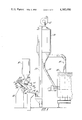
- FIG. 1 is a somewhat schematic view in elevation of overall apparatus for handling heat-softenable batch material
- FIG. 3 is a top, plan view of the apparatus of FIG. 2;
- FIG. 4 is an enlarged, diagrammatic view of a portion of the pelletizing apparatus.
- FIG. 5 is a diagrammatic view of controls for sensing batch material in the pelletizing apparatus and for controlling the flow of water to the apparatus.
- particulate, heat-softenable batch material is transported to a supply hopper 10 and supplied to a pelletizer 12.
- the particulate batch material is formed into pellets which are discharged onto a trough 14 having openings 16 (FIGS. 2 and 3) through which smaller or broken pellets can be separated.
- the pellets are supplied to a horizontal conveyor 18 and then carried up by a vertical conveyor 20 to the top of a heat-exchange hopper 22 which forms a heat-exchange chamber.
- the pellets next move down a supply tube 24 to a feeder 26 which carries the pellets into a melting unit or furnace 28.
- Hot exhaust gases or products of combustion from the furnace 28 are carried up an exhaust stack 30 to the bottom of the hopper 22.
- the exhaust gases are then drawn through the hopper 22 by a blower 32 and discharged.
- the heat-exchange hopper 22 is large enough that the exhaust gases passing therethrough will be at a low velocity and not carry some of the pellets out through the blower 32.
- a substantial portion of the heat in the exhaust gases is transferred to the pellets in the heat-exchange hopper 22 so that the pellets are at an elevated temperature when they enter the furnace 28.
- a substantial increase in efficiency of the furnace 28 is thereby achieved.
- the size uniformity of the pellets themselves is very important. If the pellet size varies too much, the pellets tend to nest together in the hopper 22 and excessively restrict the flow of the exhaust gases therethrough. However, if the pellets are of sufficiently uniform size, there will be sufficient voids among them that exhaust gases can pass through without excessive impediment.
- the nominal diameter of the pellets is also important because pellets which are too small provide excessive restriction to the flow of the exhaust gases. On the other hand, if the pellets are too large, their surface-to-weight ratio is lower and the heat transferred to them is decreased. Further, in the large pellets, moisture tends to be trapped therein and turned to steam by the exhaust gases, causing the pellets to explode.
- pellets having a nominal diameter of one-half inch with a range of three-eighths to five-eighths inch have been found to be the ultimate for obtaining maximum heat transfer from the exhaust gases to the pellets in the heat-exchange hopper 22.
- the pelletizer 12 is intended to form the particulate batch material into the one-half inch nominal diameter pellets.
- the components of the batch material supplied to the pelletizer 12 and specifically to the supply hopper 10 tend to segregate during transportation. Such segregation is not deleterious to the operation of the furnace 28 since the components of the pellets supplied thereto will average out over a period of time.
- the short variations in the batch components do affect the pellet-forming ability of the batch material. In other words, variations in the components of the batch material supplied to the pelletizer 12 will result in a change in pellet size, with other factors maintained constant.
- the feed rate of the batch to the pelletizer will also vary and change the pellet-forming ability and the pellet size with other factors being constant.
- An increased depth of the nuclei or seeds of the batch material on which the pellets are formed indicates that the seeds are tending to stick together more and thus increase in depth. This occurs when the amount of water or ratio of water to batch material increases. When the depth increases, the amount of water supplied to the pelletizer is then reduced because a continued excess of water otherwise would cause fewer but larger pellets to be formed. Also, when the depth of the nuclei or seeds is less, they tend to stick together to a lesser extent, indicating that the water content has decreased and that the pellet size accordingly will be smaller. The amount of water is then increased to prevent this.
- the pelletizer 12 includes a movable surface 34 specifically formed by a rotatable member or disc, in this instance.
- the movable surface can also take other forms, however, such as a drum or a cone for producing the pellets.
- the disc 34 is rotatably carried on a bearing housing 36 (FIG. 1) which is pivotally mounted on arms 38 carried on an axle 40 which is mounted on a stand 42.
- the disc 34 is moved or rotated by a suitable motor 44.
- An annual wall 46 surrounds the rotatable member 34 with the pellets tumbling over this wall and down a spout 47 to the trough 14 when of the final size.
- An outer cleaning plow 48 (FIGS. 2 and 3) and an inner cleaning plow 49 clean the surface of the rotatable member 34.
- Batch from the supply hopper 10 is supplied to a lower central portion of the rotatable member 34, as indicated in FIG. 4, by a suitable feeder 50.
- the feeder 50 is shown as having a belt conveyor 52 (FIG. 2) driven by a motor 54; however, other conveyors such as vibratory conveyors can be equally well employed. While the feeder is intended to supply a constant quantity of batch, as a practical matter, the feed rate of substantially any feeder is subject to some variation. This requires changes in the water supply even though the batch components do not vary.
- water is supplied to a lower central portion of the rotatable member 34, at a portion thereof shown in FIG. 4, by a supply line or spout 56.
- the batch is carried in generally elliptical paths as it moves up the surface, the surface being maintained at a preset angle to the horizontal, such as 45°, as determined by the position of the legs 38.
- the wet batch moves in three rather distinct streams or paths as it is carried up the moving surface and falls back.
- the outer path are seeds or nuclei of the batch on which the pellets form.
- the middle path are partially formed pellets having diameters in the range of one-fourth to three-eighths inch when pellets having a nominal diameter of one-half inch are to be produced.
- the inner path are finished pellets which roll in a tight elliptical path until they tumble over the annular wall 46.
- the particulate batch material gathers thereon in continuous layers to gradually increase the diameters of the partially formed pellets until the desired size is attained.
- moisture or water is introduced to the agitated mass of particulate material, the capillary force of the water and the mechanical force of the agitation of the particulate material against the moving surface causes packing and coalescing of the material into firm bodies.
- the agglomeration tendency of the particulate batch material is decreased with more nuclei or seeds forming, which results in more but smaller pellets since there are more nuclei on which a given amount of batch can form, and there is a lesser tendency for the batch to agglomerate.
- the water supply through the spout 56 to the moving surface 34 can be controlled by the system shown diagrammatically in FIG. 5. Accordingly, water is supplied to the spout 56 through a first branch passage or line 58 having a manually-controlled valve 60 therein. Water can also be supplied to the spout 56 through a second branch passage or line 62 having a solenoid-operated valve 64 and a manually-controlled valve 65 for adjustment. Water for both of the lines 58 and 62 can be supplied through a suitable supply line 66.
- the flow of water through the line 58 to the spout 56 is such as to be less than the amount needed to produce the desired size pellets on the pelletizer 12. However, the flow of water through both of the lines 58 and 62, when the valve 64 is open, is in excess of the amount needed for producing pellets of the desired size.
- a water supply of forty gallons per hour may be required to produce pellets of a given nominal diameter.
- the amount of water may need to be varied from perhaps 35-45 gallons per hour in order to maintain the pellet size relatively constant.
- the water flow through the first branch passage 58 can be set at 30 gallons per hour, below the minimum required.
- the supply of water through the second branch passage 62 can then be set at 20 gallons per hour.
- the combined flow through both of the passages 58 and 62 will then be 50 gallons per hour, which is in excess of the maximum quantity of water required.
- liquid flow through the passage 58 is supplemented from time-to-time by flow through the passage 62 to obtain the pellets of the desired nominal diameter.
- the control of the water through the passages 58 and 62 is regulated by a suitable sensing device which senses a physical characteristic of the particulate batch material on the surface 34.
- the sensing device can sense the water content, as previously discussed, and can do this by sensing the depth of the nuclei or partially formed pellets moving in the outer or middle streams on the surface 34.
- the solenoid valve 64 is controlled through a timer 68 which, when energized, supplies power through contacts therein to the solenoid of the valve 64 for a predetermined period of time, such as four seconds. Power to energize the timer, in turn, is controlled through a switch 70.
- the switch 70 has an actuating stem 72 connected with an arm 74 supporting a sensor or paddle 76.
- the arm 74 is pivotally supported by an overhead bar 78 connected to a post 80 at one side of the pelletizer wall 46.
- the arm 74 is normally held against the stem 72 by a spring 82 to keep the switch 70 open.
- the paddle 76 is located near the annular wall 46 above an upper, outer portion of the surface 34 of the pelletizer. It preferably is in a position to determine the depth of the seeds or nuclei in the outer path of the batch material on the moving surface 34 but can also sense the depth of the partially formed pellets. When the depth of the batch material, whether seeds or pellets, reaches a predetermined amount or level, the paddle 76 is contacted and moved in a counterclockwise direction, as viewed in FIG. 5. The batch material, as discussed before, reaches the predetermined depth when the water content increases and causes it to stick together and build up. Consequently, when this condition occurs, it is desired to decrease the amount of water in the batch or decrease the ratio of the water to batch.
- the senor, or paddle can be employed to control the flow of the batch material by the feeder 50.
- the motor 54 can be a two-speed motor to drive the belt 52 at different speeds. If a vibrating feeder is employed, the rate of vibration can be controlled for the same purpose. Thus, instead of increasing the flow of water, the batch feed can be decreased, and vice versa.
- the depth of the pellets can be sensed by an electric eye.
- ultrasonic waves or microwaves can be employed for this purpose.
- the sensing device can directly measure the water content of the particulate batch material, such as by infrared rays.
Abstract
Description
Claims (3)
Priority Applications (1)
| Application Number | Priority Date | Filing Date | Title |
|---|---|---|---|
| US06/318,883 US4382050A (en) | 1977-06-24 | 1981-11-06 | Method for handling heat-softenable batch material |
Applications Claiming Priority (2)
| Application Number | Priority Date | Filing Date | Title |
|---|---|---|---|
| US80959577A | 1977-06-24 | 1977-06-24 | |
| US06/318,883 US4382050A (en) | 1977-06-24 | 1981-11-06 | Method for handling heat-softenable batch material |
Related Parent Applications (1)
| Application Number | Title | Priority Date | Filing Date |
|---|---|---|---|
| US06049865 Continuation | 1979-06-18 |
Publications (1)
| Publication Number | Publication Date |
|---|---|
| US4382050A true US4382050A (en) | 1983-05-03 |
Family
ID=26981721
Family Applications (1)
| Application Number | Title | Priority Date | Filing Date |
|---|---|---|---|
| US06/318,883 Expired - Fee Related US4382050A (en) | 1977-06-24 | 1981-11-06 | Method for handling heat-softenable batch material |
Country Status (1)
| Country | Link |
|---|---|
| US (1) | US4382050A (en) |
Cited By (2)
| Publication number | Priority date | Publication date | Assignee | Title |
|---|---|---|---|---|
| US20030109640A1 (en) * | 2001-11-30 | 2003-06-12 | Lee James Gao | Process and apparatus for crystallization of polytrimethylene terephthalate (PTT) |
| US20080206386A1 (en) * | 2004-11-04 | 2008-08-28 | Sergio Francisco Valter | Device for Eliminating Oversize Pellets from Balling Disks |
Citations (2)
| Publication number | Priority date | Publication date | Assignee | Title |
|---|---|---|---|---|
| US3883281A (en) * | 1974-06-21 | 1975-05-13 | Ferro Tech | Pelletizing disc assembly and control system |
| US4091060A (en) * | 1975-07-29 | 1978-05-23 | British Steel Corporation | Balling process |
-
1981
- 1981-11-06 US US06/318,883 patent/US4382050A/en not_active Expired - Fee Related
Patent Citations (2)
| Publication number | Priority date | Publication date | Assignee | Title |
|---|---|---|---|---|
| US3883281A (en) * | 1974-06-21 | 1975-05-13 | Ferro Tech | Pelletizing disc assembly and control system |
| US4091060A (en) * | 1975-07-29 | 1978-05-23 | British Steel Corporation | Balling process |
Cited By (6)
| Publication number | Priority date | Publication date | Assignee | Title |
|---|---|---|---|---|
| US20030109640A1 (en) * | 2001-11-30 | 2003-06-12 | Lee James Gao | Process and apparatus for crystallization of polytrimethylene terephthalate (PTT) |
| US6740733B2 (en) | 2001-11-30 | 2004-05-25 | Shell Oil Company | Process and apparatus for crystallization of polytrimethylene terephthalate (PTT) |
| US20040176565A1 (en) * | 2001-11-30 | 2004-09-09 | Lee James Gao | Process and apparatus for crystallization of polytrimethylene terephthalate (PTT) |
| US6984116B2 (en) | 2001-11-30 | 2006-01-10 | Shell Oil Company | Process and apparatus for crystallization of polytrimethylene terephthalate (PTT) |
| US20080206386A1 (en) * | 2004-11-04 | 2008-08-28 | Sergio Francisco Valter | Device for Eliminating Oversize Pellets from Balling Disks |
| US8162649B2 (en) * | 2004-11-04 | 2012-04-24 | Companhia Vale Do Rio Doce | Device for eliminating oversize pellets from balling disks |
Similar Documents
| Publication | Publication Date | Title |
|---|---|---|
| US2436771A (en) | Method of making pellets | |
| JP6800895B2 (en) | Methods and devices for producing expanded granules | |
| US4030205A (en) | Drying system for particles | |
| US4344747A (en) | Sensing apparatus for pelletizing process | |
| US4212613A (en) | Apparatus for handling heat-softenable batch material | |
| US4064638A (en) | Apparatus for drying seeds | |
| US3378245A (en) | Apparatus for controllably expanding expandable material | |
| EP0013182A1 (en) | Method and apparatus for controlling a pelletizing operation | |
| US3253533A (en) | Puffing food products | |
| US4319903A (en) | Method and apparatus for preheating glass batch | |
| US4382050A (en) | Method for handling heat-softenable batch material | |
| CA1094298A (en) | Method and apparatus for handling heat-softenable batch material | |
| USRE31574E (en) | Apparatus for handling heat-softenable batch material | |
| US5019994A (en) | Method and apparatus for drying articles in a continuous feed process | |
| US3679416A (en) | Agglomeration of powdered coffee | |
| US4080134A (en) | Apparatus for pelletizing plastic material | |
| US4854941A (en) | Method and apparatus for drying fine coal | |
| US4742463A (en) | Method and apparatus for a pellet mill controller with die temperature control | |
| US4222176A (en) | Method and apparatus for drying granulated dielectric materials | |
| US4339402A (en) | Batch pelletizing: a means for measuring pellet size during the forming process | |
| EP0137556B1 (en) | A continuous coffee roaster | |
| US3204341A (en) | Process and apparatus for drying wet particulate material to a desired moisture content | |
| JP3624114B2 (en) | Rotary bread granulator and method for producing granulated product using the granulator | |
| US4330246A (en) | Apparatus for controlling the proportion of liquid and dry particulate matter added to a pelletizer | |
| US5251826A (en) | Tumbling media mill and control system |
Legal Events
| Date | Code | Title | Description |
|---|---|---|---|
| FEPP | Fee payment procedure |
Free format text: PAYOR NUMBER ASSIGNED (ORIGINAL EVENT CODE: ASPN); ENTITY STATUS OF PATENT OWNER: LARGE ENTITY |
|
| MAFP | Maintenance fee payment |
Free format text: PAYMENT OF MAINTENANCE FEE, 4TH YEAR, PL 96-517 (ORIGINAL EVENT CODE: M170); ENTITY STATUS OF PATENT OWNER: LARGE ENTITY Year of fee payment: 4 |
|
| AS | Assignment |
Owner name: WILMINGTON TRUST COMPANY, ONE RODNEY SQUARE NORTH, Free format text: SECURITY INTEREST;ASSIGNOR:OWENS-CORNING FIBERGLAS CORPORATION;REEL/FRAME:004652/0351 Effective date: 19861103 Owner name: WADE, WILLIAM, J., ONE RODNEY SQUARE NORTH, WILMIN Free format text: SECURITY INTEREST;ASSIGNOR:OWENS-CORNING FIBERGLAS CORPORATION;REEL/FRAME:004652/0351 Effective date: 19861103 Owner name: WILMINGTON TRUST COMPANY, DELAWARE Free format text: SECURITY INTEREST;ASSIGNOR:OWENS-CORNING FIBERGLAS CORPORATION;REEL/FRAME:004652/0351 Effective date: 19861103 Owner name: WADE, WILLIAM, J., DELAWARE Free format text: SECURITY INTEREST;ASSIGNOR:OWENS-CORNING FIBERGLAS CORPORATION;REEL/FRAME:004652/0351 Effective date: 19861103 |
|
| AS | Assignment |
Owner name: OWENS-CORNING FIBERGLAS CORPORATION, FIBERGLAS TOW Free format text: TERMINATION OF SECURITY AGREEMENT RECORDED NOV. 13, 1986. REEL 4652 FRAMES 351-420;ASSIGNORS:WILMINGTON TRUST COMPANY, A DE. BANKING CORPORATION;WADE, WILLIAM J. (TRUSTEES);REEL/FRAME:004903/0501 Effective date: 19870730 Owner name: OWENS-CORNING FIBERGLAS CORPORATION, A CORP. OF DE Free format text: TERMINATION OF SECURITY AGREEMENT RECORDED NOV. 13, 1986. REEL 4652 FRAMES 351-420;ASSIGNORS:WILMINGTON TRUST COMPANY, A DE. BANKING CORPORATION;WADE, WILLIAM J. (TRUSTEES);REEL/FRAME:004903/0501 Effective date: 19870730 |
|
| MAFP | Maintenance fee payment |
Free format text: PAYMENT OF MAINTENANCE FEE, 8TH YEAR, PL 96-517 (ORIGINAL EVENT CODE: M171); ENTITY STATUS OF PATENT OWNER: LARGE ENTITY Year of fee payment: 8 |
|
| AS | Assignment |
Owner name: OWENS-CORNING FIBERGLAS TECHNOLOGY INC., ILLINOIS Free format text: ASSIGNMENT OF ASSIGNORS INTEREST.;ASSIGNOR:OWENS-CORNING FIBERGLAS CORPORATION, A CORP. OF DE;REEL/FRAME:006041/0175 Effective date: 19911205 |
|
| FEPP | Fee payment procedure |
Free format text: PAYOR NUMBER ASSIGNED (ORIGINAL EVENT CODE: ASPN); ENTITY STATUS OF PATENT OWNER: LARGE ENTITY Free format text: PAYER NUMBER DE-ASSIGNED (ORIGINAL EVENT CODE: RMPN); ENTITY STATUS OF PATENT OWNER: LARGE ENTITY |
|
| FEPP | Fee payment procedure |
Free format text: MAINTENANCE FEE REMINDER MAILED (ORIGINAL EVENT CODE: REM.); ENTITY STATUS OF PATENT OWNER: LARGE ENTITY |
|
| LAPS | Lapse for failure to pay maintenance fees | ||
| FP | Lapsed due to failure to pay maintenance fee |
Effective date: 19950503 |
|
| STCH | Information on status: patent discontinuation |
Free format text: PATENT EXPIRED DUE TO NONPAYMENT OF MAINTENANCE FEES UNDER 37 CFR 1.362 |