US4378564A - Ink jet printing apparatus and process - Google Patents
Ink jet printing apparatus and process Download PDFInfo
- Publication number
- US4378564A US4378564A US06/243,240 US24324081A US4378564A US 4378564 A US4378564 A US 4378564A US 24324081 A US24324081 A US 24324081A US 4378564 A US4378564 A US 4378564A
- Authority
- US
- United States
- Prior art keywords
- ink
- solenoid valves
- nozzles
- percent
- weight
- Prior art date
- Legal status (The legal status is an assumption and is not a legal conclusion. Google has not performed a legal analysis and makes no representation as to the accuracy of the status listed.)
- Expired - Lifetime
Links
Images

Classifications
-
- C—CHEMISTRY; METALLURGY
- C09—DYES; PAINTS; POLISHES; NATURAL RESINS; ADHESIVES; COMPOSITIONS NOT OTHERWISE PROVIDED FOR; APPLICATIONS OF MATERIALS NOT OTHERWISE PROVIDED FOR
- C09D—COATING COMPOSITIONS, e.g. PAINTS, VARNISHES OR LACQUERS; FILLING PASTES; CHEMICAL PAINT OR INK REMOVERS; INKS; CORRECTING FLUIDS; WOODSTAINS; PASTES OR SOLIDS FOR COLOURING OR PRINTING; USE OF MATERIALS THEREFOR
- C09D11/00—Inks
- C09D11/30—Inkjet printing inks
-
- B—PERFORMING OPERATIONS; TRANSPORTING
- B41—PRINTING; LINING MACHINES; TYPEWRITERS; STAMPS
- B41J—TYPEWRITERS; SELECTIVE PRINTING MECHANISMS, i.e. MECHANISMS PRINTING OTHERWISE THAN FROM A FORME; CORRECTION OF TYPOGRAPHICAL ERRORS
- B41J2/00—Typewriters or selective printing mechanisms characterised by the printing or marking process for which they are designed
- B41J2/005—Typewriters or selective printing mechanisms characterised by the printing or marking process for which they are designed characterised by bringing liquid or particles selectively into contact with a printing material
- B41J2/01—Ink jet
- B41J2/015—Ink jet characterised by the jet generation process
- B41J2/04—Ink jet characterised by the jet generation process generating single droplets or particles on demand
-
- B—PERFORMING OPERATIONS; TRANSPORTING
- B41—PRINTING; LINING MACHINES; TYPEWRITERS; STAMPS
- B41J—TYPEWRITERS; SELECTIVE PRINTING MECHANISMS, i.e. MECHANISMS PRINTING OTHERWISE THAN FROM A FORME; CORRECTION OF TYPOGRAPHICAL ERRORS
- B41J3/00—Typewriters or selective printing or marking mechanisms characterised by the purpose for which they are constructed
- B41J3/28—Typewriters or selective printing or marking mechanisms characterised by the purpose for which they are constructed for printing downwardly on flat surfaces, e.g. of books, drawings, boxes, envelopes, e.g. flat-bed ink-jet printers
- B41J3/286—Typewriters or selective printing or marking mechanisms characterised by the purpose for which they are constructed for printing downwardly on flat surfaces, e.g. of books, drawings, boxes, envelopes, e.g. flat-bed ink-jet printers on boxes
-
- B—PERFORMING OPERATIONS; TRANSPORTING
- B41—PRINTING; LINING MACHINES; TYPEWRITERS; STAMPS
- B41J—TYPEWRITERS; SELECTIVE PRINTING MECHANISMS, i.e. MECHANISMS PRINTING OTHERWISE THAN FROM A FORME; CORRECTION OF TYPOGRAPHICAL ERRORS
- B41J3/00—Typewriters or selective printing or marking mechanisms characterised by the purpose for which they are constructed
- B41J3/407—Typewriters or selective printing or marking mechanisms characterised by the purpose for which they are constructed for marking on special material
- B41J3/4073—Printing on three-dimensional objects not being in sheet or web form, e.g. spherical or cubic objects
Definitions
- This invention relates generally to ink jet printing and specifically to an ink jet printing apparatus and method for printing alpha-numeric characters onto a moving surface, such as containers moving along a conveyor.
- Ink jet printing devices can be broadly divided into two categories, continuous and so called "on-demand" technology.
- an ink manifold houses a piezoelectric crystal which vibrates upon application of an electric signal. The vibrations force ink out a nozzle past an electrode which charges selected drops.
- the ink stream continues through charged plates where the charged particles are deflected upward onto a target. The unchanged drops fall into a collection tray and are recirculated.
- Such devices are generally used for high speed printing with quality comparable to a typewriter and all rely upon a continuous, synchronized stream of ink drops.
- On-demand ink jet printing devices utilize some variation of a technique in which ink drops are issued only on demand rather than in a continuous stream.
- a plurality of nozzles through which ink can be intermittently selectively ejected.
- Prior devices of this kind have generally comprised either piezoelectric ejector means associated with each nozzle for ejecting ink therethrough or an electrically operated needle valve or plunger for opening and closing each nozzle.
- the apparatus is relatively complex and uses only parts which have to be specially manufactured with the result that the apparatus tends to be extremely costly.
- Such devices were not well suited for the packaging industry where larger characters, for instance, characters having a height of from 13 mm to 70 mm are printed on containers moving down a conveyor line.
- an object of the present invention to provide an ink jet printing apparatus suitable for printing large size alpha-numeric characters on a moving surface which apparatus is simple and dependable in operation and economical to construct.
- Another object of the invention is to provide an ink jet printing process which utilizes an ink matched to the apparatus to provide satisfactory wetting of the printing substrate without drying in the apparatus nozzles.
- the improved ink jet printing apparatus of this invention includes a source of pressurized ink and a plurality of valves, each of the valves having an input port which is in fluid communication with the pressurized ink source and an output port.
- a plurality of jeweled orifice nozzles are provided, each of which is in fluid communication with a select one of the output ports of the valves.
- Control means control the output of the ink from the valves to the nozzles.
- an ink manifold communicates with the pressurized ink source.
- a plurality of solenoid valves have input ports which are connected by means of fluid conduits to the ink manifold.
- the output ports of the solenoid valves are connected by means of fluid conduits to the jeweled nozzles.
- the nozzle orifices are in the range of 0.025 mm to 0.215 mm in diameter.
- a source of pressurized water-based ink which comprises 60 to 95 percent by weight water, 0.05 to 25 percent by weight dye, and 2.5 to 20 percent by weight glycol ether.
- the pressurized ink source is connected to a plurality of solenoid valves which are in turn connected to individual jeweled orifice nozzles.
- An electrical control means controls the output of the solenoid valves to the nozzles.
- the glycol ether is preferably a mixture of 2 to 8 percent by weight butyl cellosolve and 2 to 8 percent by weight butyl carbitol, said percentages being based on the total weight of the water-based ink.
- the relative proportions of the glycol ethers are selected to produce an ink having a viscosity in the range of 1.4 to 3.2 centipoise.
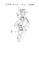
- FIG. 1 is a perspective view of the ink jet printing apparatus installed on a conveyor line.
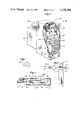
- FIG. 2 is an exploded view of the print head of the device of FIG. 1.
- FIG. 3 is a close-up view of the ink source of the device of FIG. 1 partially broken away;
- FIG. 4 is a cross-sectional view of a valve used in the print head taken along lines IV--IV in FIG. 2.
- FIG. 5 is a cross-sectional view of the nozzle block of the print head taken along lines V--V in FIG. 2.
- FIG. 6 is a front isolated view of one of the nozzles used in the nozzle blocks.
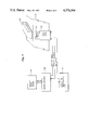
- FIG. 7 is a schematic of the electrical control circuit of the apparatus of FIG. 1.
- FIG. 1 there is shown an ink jet printing apparatus of the present invention in place on a packaging line.
- a print head designated generally as 11, has a plurality of nozzles 13 used to print alphanumeric characters onto a container 15 as the container moves down a conveyor 17.
- a source of pressurized ink 19 communicates by means of an ink line 21 with the print head 11.
- a microcomputer 23 selectively controls the ejection of ink from nozzles 13 onto container 15 in response to a message input device 25 programmed by the operator.
- a photocell 27 is used to detect the leading edge of the container as it passes in front of the print-head 11 to cause subsequent printing.
- the print head 11 has a plurality of nozzles 29 provided in a common nozzle block 31.
- the nozzles are arranged in a single column in alignment with and at equally spaced intervals from one another although other arrangements are possible such as arranging the alternate nozzles in two columns parallel with one another.
- Each nozzle 29 comprises a single aperture for the passage of ink.
- each nozzle 29 can comprise a plurality of apertures which provide the same cross-sectional area as the single aperture.
- the nozzles 29 are preferably jeweled orifice nozzles such as the sapphire jewels used in acetylene torches and the like.
- Each jeweled orifice nozzle 29 as shown in FIGS. 5 and 6 has a generally circular body 33 having an orifice 35 of relatively smaller diameter on one face 37 and an opening 39 of relatively greater diameter on the opposite face 41.
- the diameter of orifice 35 is in the range of 0.025 mm to 0.215 mm, and preferably is in the range of 0.145 mm to 0.185 mm.
- Each nozzle 29 is set in a nozzle block 31 preferably made of an inert material such as a suitable plastic.
- the nozzle block 31 has a series of generally circular recesses 43 having an internal diameter selected to receive the external diameter of the nozzle body 33. Recesses 43 are of sufficient depth to allow the nozzles 29 to fit flush with the top surface 45 of the block 31 when the nozzles are in place.
- the nozzles 29 are placed in recesses 43 with the opening 39 being first to enter the recess 43.
- the distance between the center of each orifice 35 when the orifices are vertically aligned is in the range of 0.01 mm to 5.0 mm and preferably is in the range of 0.05 mm to 0.50 mm.
- the nozzle block 31 is backed by a longitudinal strip 47.
- a series of rigid tubes 49 leading from the nozzle recesses 43 project outward from the side of strip 47 opposite nozzle block 31.
- Tubes 49 and hence nozzles 29 are each in fluid communication with the output port 51 of a valve 53 (FIG. 2), located within the print head 11 by means of fluid conduits 50.
- Conduits 50 are of any suitable commercially available conduit, e.g., of metal or plastic material and are preferably in the range of 0.127 mm to 1.270 mm in diameter.
- Valves 53 may be any suitable commercially available fast acting valve having an electrical cycle time in the range of from 0.1 to 10 milliseconds, preferably in the range of 1.0 to 4.5 milliseconds. Suitable valves can be either a single-acting spring return, a double acting electromagnetic solenoid valve or a piezoelectric valve. Preferably a single-acting spring return solenoid valve such as shown in FIG. 4 is used. Such a valve 53 typically has an output port 51 and an input port 55 leading to a fluid chamber 57 within an outer housing 59.
- a plunger 61 closes off output port 51 when in the position shown and has an elongated body 63 which is slidably received within a solenoid coil 65, held in place by mounting collars 67, 69.
- the solenoid coil 65 and valve housing 59 are preferably coated with a suitable epoxy resin to prevent ink fluid damage.
- the solenoid coil 65 when energized exerts an electromagnetic force on plunger body 63 to cause the plunger 61 to move out of sealing engagement with output port 51, allowing ink to flow out the output port.
- Wires 73, 75 run from solenoid coil 65 to the control circuit of the microcomputer 23 by means of a data cable 66 (FIG. 2).
- valves 53 are each in fluid communication with a common ink manifold 77 by means of fluid conduits 79 which are similar to conduits 50.
- Ink manifold 77 communicates with the pressurized ink source 19 (FIGS. 1 and 3) by means of ink line 21.
- the components of the print head 11 are conveniently housed within a generally rectangular box including bottom 81, end pieces 83, 85, and top 87. End piece 83 has a centrally located slot 89 adapted to receive nozzle block 31.
- the pressurized ink source 19 (FIG. 3) comprises a reservoir 93 which can be pressurized to supply ink under pressure to ink manifold 77 by way of ink line 21.
- Pressure means such as vibrator pump 95 supply air pressure through a hose 97 to reservoir 93 which is filled with ink from the top by means of cap 99.
- Pump 95 is suspended within reservoir housing 101 by means of resilient bands 103.
- a vent valve 105 in air hose 97 allows the air pressure to reservoir 93 to be adjusted. Air pressure in the range of 0.5 to 7 psi is acceptable for the present purpose.
- a filter 107 can be utilized to filter the ink passing through ink line 21 to manifold 77.
- FIG. 7 Operation of the electrical control means comprising photocell 27, message input device 25, and microcomputer 23 is shown schematically in FIG. 7.
- a photocell 27 (FIG. 1) mounted on the print head 11 detects the leading edge of a container 15 which is moving down a conveyor 17.
- An electrical signal is fed to a microcomputer 23 which has been programmed by the operator through an input device 25 to direct the printing of a desired character message.
- the control circuit of microcomputer 23 is electrically connected to solenoid valves 53 as by wires 73, 75 (FIG. 2).
- Valves 53 are thus selectively and intermittently actuated by the electrical control means to allow ink to flow from manifold 77 through output ports 51 to jeweled orifice nozzles 29 and onto the printing substrate.
- the selective actuation of the valves 53 by the electrical control means as the container 15 moves past allows a message to be printed in a dot-matrix format.
- an acceptable ink must exhibit acceptable "wetting" characteristics on a variety of printing substrates but must not “tip dry” in the nozzles.
- the viscosity of the resulting ink should be in the range of 1.0 to 10 centipoise at 25° C. and preferably be in the range of 1.4 to 3.2 centipoise.
- a water-based ink is desired. However, a water-dye mixture alone will not sufficiently wet the printing substrate to give acceptable print.
- a suitable ink contains 60 to 95 percent by weight water, 0.05 to 25 percent by weight dye and 2.5 to 20 percent by weight glycol ether, all percentages based on the total weight of ink. Minor percentages of anti-bacterials, pH controllers, and the like can also be present, said minor components generally constituting less than one percent by weight of the total weight of ink.
- a pressurized source of water based ink is first prepared comprising 60 to 95 percent by weight water based on the weight of ink, 0.05 to 25 percent by weight dye based on the weight of ink, and 2.5 to 20 percent by weight of a glycol ether selected from the group consisting of butyl cellosolve, butyl carbitol, and mixtures thereof.
- a glycol ether selected from the group consisting of butyl cellosolve, butyl carbitol, and mixtures thereof.
- a mixture of 2 to 20 percent by weight butyl cellosolve based on the weight of ink and 2 to 20 percent butyl carbitol based on the weight of ink is used, with the most preferred ink containing 2 to 8 percent by weight butyl cellosolve and 2 to 8 percent by weight butyl carbitol.
- the resulting viscosity of the ink utilized should be in the range of 1.0 to 10 centipoise at 20° C. with the preferred range being
- the source of pressurized ink thus prepared is then connected to a plurality of solenoid valves, each of the solenoid valves having an input port in communication with the ink source and an output port.
- the output ports of the solenoid valves are connected to a plurality of jeweled orifice nozzles, the nozzle orifices being in the range of 0.025 mm to 0.215 mm in diameter.
- Electrical control means are provided for controlling the output of the solenoid valves to the nozzles.
- the ink jet printing apparatus is suitable for printing large size alpha-numeric characters on moving surfaces yet is simple in design and dependable in operation.
- the apparatus can be constructed from commercially available parts making it economical to manufacture.
- the ink jet printing process of the invention matches an ink to the specific apparatus to obtain the desired wetting characteristics on the printing substrate without "tip drying" in the nozzles.
Abstract
Description
              TABLE I
______________________________________
                butyl
     butyl      carbitol dye     water
     cellosolve % by     % by    % by
     % by weight
                weight   weight  weight
Run  of ink     of ink   of ink  of ink
                                       Remarks
______________________________________
1    8          0        2       90    Good wet-
                                       ting but
                                       tip dries
2    7          0        0.4     92.6  Good wet-
                                       ting but
                                       tip dries
3    5          3        20      72    Good wet-
                                       ting
4    5          3        2       75-87 Good wet-
                         (up to 15%    ting
                         ethanol)
5    10         7        2       71    Better
                                       wetting
6    6          5        2       87    Good wet-
                                       ting
______________________________________
Claims (3)
Applications Claiming Priority (2)
| Application Number | Priority Date | Filing Date | Title |
|---|---|---|---|
| GB8008797 | 1980-03-14 | ||
| GB8008797 | 1980-03-14 |
Publications (1)
| Publication Number | Publication Date |
|---|---|
| US4378564A true US4378564A (en) | 1983-03-29 |
Family
ID=10512123
Family Applications (1)
| Application Number | Title | Priority Date | Filing Date |
|---|---|---|---|
| US06/243,240 Expired - Lifetime US4378564A (en) | 1980-03-14 | 1981-03-13 | Ink jet printing apparatus and process |
Country Status (6)
| Country | Link |
|---|---|
| US (1) | US4378564A (en) |
| EP (1) | EP0036297A3 (en) |
| AU (1) | AU6839981A (en) |
| CA (1) | CA1165174A (en) |
| DK (1) | DK113481A (en) |
| ES (1) | ES500365A0 (en) |
Cited By (56)
| Publication number | Priority date | Publication date | Assignee | Title |
|---|---|---|---|---|
| US4460905A (en) * | 1982-03-29 | 1984-07-17 | Ncr Corporation | Control valve for ink jet nozzles |
| WO1985001104A1 (en) * | 1983-08-29 | 1985-03-14 | Diagraph Corporation | Ink jet printing system |
| WO1985001103A1 (en) * | 1983-08-31 | 1985-03-14 | Diagraph Corporation | Ink jet printing apparatus |
| WO1985002012A1 (en) * | 1983-10-31 | 1985-05-09 | Dennison Manufacturing Company | On-demand large character ink jet printer |
| US4538161A (en) * | 1982-06-01 | 1985-08-27 | Ferag Ag | Apparatus for addressing newspapers, journals and other printed products |
| US4539570A (en) * | 1983-12-09 | 1985-09-03 | Willett International Limited | Stackable fluid dispensing apparatus |
| US4549189A (en) * | 1982-06-04 | 1985-10-22 | Fuji Xerox Co., Ltd. | Thermal printing head |
| US4564846A (en) * | 1984-10-26 | 1986-01-14 | Kiwi Coders Corporation | Drop on demand dot matrix printing head |
| US4608575A (en) * | 1984-09-07 | 1986-08-26 | Printos Marsh Corporation | Computer controlled multi-tasking ink jet printing system |
| US4628330A (en) * | 1981-12-14 | 1986-12-09 | Nec | Ink-jet recording apparatus |
| WO1987001657A1 (en) * | 1985-09-20 | 1987-03-26 | Swedot System Ab | Fluid spraying head |
| US4737802A (en) * | 1984-12-21 | 1988-04-12 | Swedot System Ab | Fluid jet printing device |
| WO1988005725A1 (en) * | 1987-02-06 | 1988-08-11 | Ackley Machine Corp. | Ink-jet marker for pellet-shaped articles |
| US4769650A (en) * | 1987-08-05 | 1988-09-06 | Industrial Technology Research Institute | Automatic ink-jet marking system |
| US4792817A (en) * | 1983-08-29 | 1988-12-20 | Diagraph Corporation | Ink jet printing systems |
| EP0297753A1 (en) * | 1987-07-01 | 1989-01-04 | The Lee Company | Valve and nozzle system for ink jet printing apparatus |
| US4875058A (en) * | 1986-12-12 | 1989-10-17 | Markpoint System Ab | Valve device for a matrix printer |
| US4901095A (en) * | 1988-11-10 | 1990-02-13 | Markem Corporation | Ink jet printing apparatus with adjustable print head |
| US4905589A (en) * | 1987-02-06 | 1990-03-06 | Ackley E Michael | Ink-jet system for marking pellet-shaped articles |
| US4928111A (en) * | 1988-12-01 | 1990-05-22 | Willett International Limited | Method for operating a valve |
| US4982200A (en) * | 1985-06-13 | 1991-01-01 | Swedot System Ab | Fluid jet printing device |
| US5101224A (en) * | 1989-06-13 | 1992-03-31 | Marsh Company | Ink jet print head support |
| US5100469A (en) * | 1991-05-16 | 1992-03-31 | Xerox Corporation | Ink compositions having decreased drying times |
| US5129948A (en) * | 1991-05-16 | 1992-07-14 | Xerox Corporation | Ink for ink jet printing |
| US5144330A (en) * | 1990-12-21 | 1992-09-01 | Bennett Charles G | Method and apparatus for printing on pipe |
| US5156675A (en) * | 1991-05-16 | 1992-10-20 | Xerox Corporation | Ink for ink jet printing |
| US5211747A (en) * | 1991-05-16 | 1993-05-18 | Xerox Corporation | Ink jet ink compositions containing desizing agents |
| US5212496A (en) * | 1990-09-28 | 1993-05-18 | Xerox Corporation | Coated ink jet printhead |
| US5286286A (en) * | 1991-05-16 | 1994-02-15 | Xerox Corporation | Colorless fast-drying ink compositions for printing concealed images detectable by fluorescence |
| WO1994009988A1 (en) * | 1992-11-05 | 1994-05-11 | Videojetsystems International, Inc. | Ink jet printing |
| US5427029A (en) * | 1994-01-25 | 1995-06-27 | Professional Control Corporation | Method and apparatus for providing printed labels for large numbers of objects |
| US5463415A (en) * | 1992-05-29 | 1995-10-31 | Scitex Digital Printing, Inc. | Four inch print engine module |
| US5606349A (en) * | 1994-03-04 | 1997-02-25 | Diagraph Corporation | Ink jet system with serial data printheads |
| US5685651A (en) * | 1992-04-02 | 1997-11-11 | Esselte N.V. | Printing device |
| EP0876257A1 (en) * | 1996-01-26 | 1998-11-11 | Tetra Laval Holdings & Finance SA | Method and apparatus for printing images on packaging material |
| US5907339A (en) * | 1994-11-10 | 1999-05-25 | Diagraph Corporation | Ink jet printhead having solenoids controlling ink flow |
| US6050664A (en) * | 1996-10-11 | 2000-04-18 | Marsh Company | Adjustable slide mount for ink jet print head |
| US6409308B1 (en) * | 1999-11-19 | 2002-06-25 | Lexmark International, Inc. | Method of forming an inkjet printhead nozzle structure |
| US6557758B1 (en) * | 1999-10-01 | 2003-05-06 | Moore North America, Inc. | Direct to package printing system with RFID write/read capability |
| WO2003043554A1 (en) | 2001-11-16 | 2003-05-30 | Kimberly-Clark Worldwide, Inc. | Apparatus and method to produce topography and materials having topography |
| US20030106605A1 (en) * | 2001-11-16 | 2003-06-12 | Jameson Lee Kirby | Material having one or more chemistries which produce topography, unique fluid handling properties and/or bonding properties thereon and/or therein |
| US20040215406A1 (en) * | 2001-08-14 | 2004-10-28 | Hoen Storrs T. | Magnetically-actuated fluid control valve |
| US20050099451A1 (en) * | 2003-11-04 | 2005-05-12 | Videojet Technologies Inc. | Method and apparatus for reducing debris accumulation in an ink jet printhead |
| US7090327B1 (en) | 2002-10-03 | 2006-08-15 | Electronics For Imaging, Inc. | Water-based ink jet printer |
| US20060197816A1 (en) * | 2005-03-07 | 2006-09-07 | Fujifilm Imaging Colorants Limited | Ink compositions containing ethylene glycol monobutyl ether |
| US20080152819A1 (en) * | 2006-12-20 | 2008-06-26 | Achim Gauss | Device And Process For Coating Workpieces |
| US20080239042A1 (en) * | 2006-03-08 | 2008-10-02 | Homag Holzbearbeitungssysteme Ag | Process And Apparatus For The Printing Of Panel-Shaped Workpieces |
| US20080239048A1 (en) * | 2007-03-27 | 2008-10-02 | Homag Holzbearbeitungssysteme Ag | Device and Method for Imprinting a Three-Dimensional Article |
| US20080280028A1 (en) * | 2007-05-10 | 2008-11-13 | Homag Holzbearbeitungssysteme Ag | Method and device for coating a surface |
| US20090115825A1 (en) * | 2007-11-01 | 2009-05-07 | Industrial Technology Research Institute | Droplet ejection device for a highly viscous liquid |
| US20100229791A1 (en) * | 2006-06-12 | 2010-09-16 | Konica Minolta Holdings, Inc. | Coating apparatus |
| WO2011104522A1 (en) | 2010-02-23 | 2011-09-01 | Fujifilm Imaging Colorants, Inc. | Inks |
| US20140063158A1 (en) * | 2012-08-29 | 2014-03-06 | Xerox Corporation | Systems and methods for printing differential gloss image on packaging |
| WO2014202519A1 (en) | 2013-06-18 | 2014-12-24 | Agfa Graphics Nv | Method for manufacturing a lithographic printing plate precursor having a patterned back layer |
| US10105900B2 (en) | 2013-08-14 | 2018-10-23 | Homag Holzbearbeitungssysteme Gmbh | Coating unit |
| US20190168504A1 (en) * | 2017-05-12 | 2019-06-06 | Roboprint Co., Ltd. | Image processing method, automatic image printing method, and automatic printing apparatus nozzle |
Families Citing this family (7)
| Publication number | Priority date | Publication date | Assignee | Title |
|---|---|---|---|---|
| EP0113537A1 (en) * | 1982-12-13 | 1984-07-18 | Willett International Limited | Method of applying an adhesive composition |
| DE3302616A1 (en) * | 1983-01-27 | 1984-08-02 | Cyklop International Emil Hoffmann KG, 5000 Köln | DEVICE FOR SIGNING OBJECTS |
| DE3302617A1 (en) * | 1983-01-27 | 1984-08-02 | Cyklop International Emil Hoffmann KG, 5000 Köln | COLOR SPRAY HEAD |
| WO1986001775A1 (en) * | 1984-09-19 | 1986-03-27 | Ronald Douglas Drysdale | Method of and apparatus for applying images to a surface |
| DE3434334A1 (en) * | 1984-09-19 | 1986-03-27 | Robert Bosch Gmbh, 7000 Stuttgart | METHOD FOR APPLYING SUSPENSIONS OF BURNABLE SOLIDS TO CERAMIC OR GLASS SUBSTRATES, AND DEVICE FOR CARRYING OUT THE METHOD |
| US5316397A (en) * | 1992-07-31 | 1994-05-31 | Telesis Marking Systems, Inc. | Marking apparatus with multiple marking modes |
| JP2887307B2 (en) * | 1995-12-05 | 1999-04-26 | 株式会社ヤクルト本社 | Printing mechanism for circular cross-section containers |
Citations (8)
| Publication number | Priority date | Publication date | Assignee | Title |
|---|---|---|---|---|
| US3266526A (en) * | 1962-11-26 | 1966-08-16 | Robert H Berg | Peripherally locked and sealed orifice disk and method |
| US3584571A (en) * | 1967-08-25 | 1971-06-15 | Pannier Corp The | Character generation marking device |
| US3653596A (en) * | 1970-01-13 | 1972-04-04 | Carco Inc | Marking device |
| US3717722A (en) * | 1970-04-27 | 1973-02-20 | J Messner | Apparatus for printing continuous runs of material |
| US3972474A (en) * | 1974-11-01 | 1976-08-03 | A. B. Dick Company | Miniature ink jet nozzle |
| US4002230A (en) * | 1975-07-09 | 1977-01-11 | Houston Engineering Research Corporation | Print head apparatus |
| US4150997A (en) * | 1978-04-24 | 1979-04-24 | Recognition Equipment Incorporated | Water base fluorescent ink for ink jet printing |
| US4215350A (en) * | 1978-04-19 | 1980-07-29 | Mielke Klaus H | Ink jet printing apparatus with two different jet spacings |
Family Cites Families (1)
| Publication number | Priority date | Publication date | Assignee | Title |
|---|---|---|---|---|
| US4299630A (en) * | 1977-04-27 | 1981-11-10 | The Mead Corporation | Infrared absorptive jet printing ink |
-
1981
- 1981-03-12 EP EP81301032A patent/EP0036297A3/en not_active Withdrawn
- 1981-03-13 CA CA000373019A patent/CA1165174A/en not_active Expired
- 1981-03-13 US US06/243,240 patent/US4378564A/en not_active Expired - Lifetime
- 1981-03-13 DK DK113481A patent/DK113481A/en not_active Application Discontinuation
- 1981-03-14 ES ES500365A patent/ES500365A0/en active Granted
- 1981-03-16 AU AU68399/81A patent/AU6839981A/en not_active Abandoned
Patent Citations (8)
| Publication number | Priority date | Publication date | Assignee | Title |
|---|---|---|---|---|
| US3266526A (en) * | 1962-11-26 | 1966-08-16 | Robert H Berg | Peripherally locked and sealed orifice disk and method |
| US3584571A (en) * | 1967-08-25 | 1971-06-15 | Pannier Corp The | Character generation marking device |
| US3653596A (en) * | 1970-01-13 | 1972-04-04 | Carco Inc | Marking device |
| US3717722A (en) * | 1970-04-27 | 1973-02-20 | J Messner | Apparatus for printing continuous runs of material |
| US3972474A (en) * | 1974-11-01 | 1976-08-03 | A. B. Dick Company | Miniature ink jet nozzle |
| US4002230A (en) * | 1975-07-09 | 1977-01-11 | Houston Engineering Research Corporation | Print head apparatus |
| US4215350A (en) * | 1978-04-19 | 1980-07-29 | Mielke Klaus H | Ink jet printing apparatus with two different jet spacings |
| US4150997A (en) * | 1978-04-24 | 1979-04-24 | Recognition Equipment Incorporated | Water base fluorescent ink for ink jet printing |
Cited By (76)
| Publication number | Priority date | Publication date | Assignee | Title |
|---|---|---|---|---|
| US4628330A (en) * | 1981-12-14 | 1986-12-09 | Nec | Ink-jet recording apparatus |
| US4460905A (en) * | 1982-03-29 | 1984-07-17 | Ncr Corporation | Control valve for ink jet nozzles |
| US4538161A (en) * | 1982-06-01 | 1985-08-27 | Ferag Ag | Apparatus for addressing newspapers, journals and other printed products |
| US4549189A (en) * | 1982-06-04 | 1985-10-22 | Fuji Xerox Co., Ltd. | Thermal printing head |
| US4792817A (en) * | 1983-08-29 | 1988-12-20 | Diagraph Corporation | Ink jet printing systems |
| WO1985001104A1 (en) * | 1983-08-29 | 1985-03-14 | Diagraph Corporation | Ink jet printing system |
| WO1985001103A1 (en) * | 1983-08-31 | 1985-03-14 | Diagraph Corporation | Ink jet printing apparatus |
| WO1985002012A1 (en) * | 1983-10-31 | 1985-05-09 | Dennison Manufacturing Company | On-demand large character ink jet printer |
| US4539570A (en) * | 1983-12-09 | 1985-09-03 | Willett International Limited | Stackable fluid dispensing apparatus |
| US4608575A (en) * | 1984-09-07 | 1986-08-26 | Printos Marsh Corporation | Computer controlled multi-tasking ink jet printing system |
| US4564846A (en) * | 1984-10-26 | 1986-01-14 | Kiwi Coders Corporation | Drop on demand dot matrix printing head |
| US4737802A (en) * | 1984-12-21 | 1988-04-12 | Swedot System Ab | Fluid jet printing device |
| US4982200A (en) * | 1985-06-13 | 1991-01-01 | Swedot System Ab | Fluid jet printing device |
| WO1987001657A1 (en) * | 1985-09-20 | 1987-03-26 | Swedot System Ab | Fluid spraying head |
| US4789871A (en) * | 1985-09-20 | 1988-12-06 | Swedot Jet Mark Ab | Fluid spraying head |
| US4875058A (en) * | 1986-12-12 | 1989-10-17 | Markpoint System Ab | Valve device for a matrix printer |
| WO1988005725A1 (en) * | 1987-02-06 | 1988-08-11 | Ackley Machine Corp. | Ink-jet marker for pellet-shaped articles |
| US4905589A (en) * | 1987-02-06 | 1990-03-06 | Ackley E Michael | Ink-jet system for marking pellet-shaped articles |
| EP0297753A1 (en) * | 1987-07-01 | 1989-01-04 | The Lee Company | Valve and nozzle system for ink jet printing apparatus |
| US4819009A (en) * | 1987-07-01 | 1989-04-04 | Marsh Company | Valve and nozzle system for ink jet printing apparatus |
| US4769650A (en) * | 1987-08-05 | 1988-09-06 | Industrial Technology Research Institute | Automatic ink-jet marking system |
| US4901095A (en) * | 1988-11-10 | 1990-02-13 | Markem Corporation | Ink jet printing apparatus with adjustable print head |
| US4928111A (en) * | 1988-12-01 | 1990-05-22 | Willett International Limited | Method for operating a valve |
| US5101224A (en) * | 1989-06-13 | 1992-03-31 | Marsh Company | Ink jet print head support |
| US5212496A (en) * | 1990-09-28 | 1993-05-18 | Xerox Corporation | Coated ink jet printhead |
| US5144330A (en) * | 1990-12-21 | 1992-09-01 | Bennett Charles G | Method and apparatus for printing on pipe |
| US5156675A (en) * | 1991-05-16 | 1992-10-20 | Xerox Corporation | Ink for ink jet printing |
| US5211747A (en) * | 1991-05-16 | 1993-05-18 | Xerox Corporation | Ink jet ink compositions containing desizing agents |
| US5100469A (en) * | 1991-05-16 | 1992-03-31 | Xerox Corporation | Ink compositions having decreased drying times |
| US5286286A (en) * | 1991-05-16 | 1994-02-15 | Xerox Corporation | Colorless fast-drying ink compositions for printing concealed images detectable by fluorescence |
| US5129948A (en) * | 1991-05-16 | 1992-07-14 | Xerox Corporation | Ink for ink jet printing |
| US5685651A (en) * | 1992-04-02 | 1997-11-11 | Esselte N.V. | Printing device |
| US5463415A (en) * | 1992-05-29 | 1995-10-31 | Scitex Digital Printing, Inc. | Four inch print engine module |
| WO1994009988A1 (en) * | 1992-11-05 | 1994-05-11 | Videojetsystems International, Inc. | Ink jet printing |
| US5461401A (en) * | 1992-11-05 | 1995-10-24 | Videojet Systems International, Inc. | Frequency optimized ink jet printer |
| US5427029A (en) * | 1994-01-25 | 1995-06-27 | Professional Control Corporation | Method and apparatus for providing printed labels for large numbers of objects |
| US5606349A (en) * | 1994-03-04 | 1997-02-25 | Diagraph Corporation | Ink jet system with serial data printheads |
| US5825375A (en) * | 1994-03-04 | 1998-10-20 | Diagraph Corporation | Ink jet system with serial data printheads |
| US5907339A (en) * | 1994-11-10 | 1999-05-25 | Diagraph Corporation | Ink jet printhead having solenoids controlling ink flow |
| EP0876257A1 (en) * | 1996-01-26 | 1998-11-11 | Tetra Laval Holdings & Finance SA | Method and apparatus for printing images on packaging material |
| EP0876257A4 (en) * | 1996-01-26 | 1999-04-28 | Tetra Laval Holdings & Finance | Method and apparatus for printing images on packaging material |
| US6050664A (en) * | 1996-10-11 | 2000-04-18 | Marsh Company | Adjustable slide mount for ink jet print head |
| US6464314B1 (en) | 1996-10-11 | 2002-10-15 | Videojet Systems International, Inc. | Ink jet printhead mount |
| US6557758B1 (en) * | 1999-10-01 | 2003-05-06 | Moore North America, Inc. | Direct to package printing system with RFID write/read capability |
| US6409308B1 (en) * | 1999-11-19 | 2002-06-25 | Lexmark International, Inc. | Method of forming an inkjet printhead nozzle structure |
| US7111929B2 (en) * | 2001-08-14 | 2006-09-26 | Hewlett-Packard Development Company, Lp | Magnetically-actuated fluid control valve |
| US20040215406A1 (en) * | 2001-08-14 | 2004-10-28 | Hoen Storrs T. | Magnetically-actuated fluid control valve |
| US20030106605A1 (en) * | 2001-11-16 | 2003-06-12 | Jameson Lee Kirby | Material having one or more chemistries which produce topography, unique fluid handling properties and/or bonding properties thereon and/or therein |
| WO2003043554A1 (en) | 2001-11-16 | 2003-05-30 | Kimberly-Clark Worldwide, Inc. | Apparatus and method to produce topography and materials having topography |
| US7090327B1 (en) | 2002-10-03 | 2006-08-15 | Electronics For Imaging, Inc. | Water-based ink jet printer |
| US20060221157A1 (en) * | 2002-10-03 | 2006-10-05 | Duffield John P | Apparatus and methods for water-based ink printing |
| US20080316236A1 (en) * | 2002-10-03 | 2008-12-25 | Duffield John P | Apparatus and methods for water-based ink printing |
| US7396119B2 (en) | 2002-10-03 | 2008-07-08 | Electronics For Imaging, Inc. | Apparatus and methods for water-based ink printing |
| US20050099451A1 (en) * | 2003-11-04 | 2005-05-12 | Videojet Technologies Inc. | Method and apparatus for reducing debris accumulation in an ink jet printhead |
| US20060197816A1 (en) * | 2005-03-07 | 2006-09-07 | Fujifilm Imaging Colorants Limited | Ink compositions containing ethylene glycol monobutyl ether |
| GB2423995A (en) * | 2005-03-07 | 2006-09-13 | Fujifilm Imaging Colorants Ltd | Ink compositions containing ethylene glycol monobutyl ether |
| GB2423995B (en) * | 2005-03-07 | 2007-05-02 | Fujifilm Imaging Colorants Ltd | Ink compositions containing ethylene glycol monobutyl ether |
| US7427320B2 (en) | 2005-03-07 | 2008-09-23 | Fujifilm Imaging Colorants Limited | Ink compositions containing ethylene glycol monobutyl ether |
| US20080239042A1 (en) * | 2006-03-08 | 2008-10-02 | Homag Holzbearbeitungssysteme Ag | Process And Apparatus For The Printing Of Panel-Shaped Workpieces |
| US8366260B2 (en) | 2006-03-08 | 2013-02-05 | Homag Holzbearbeitungssysteme Ag | Process and apparatus for the printing of panel-shaped workpieces |
| US8297218B2 (en) * | 2006-06-12 | 2012-10-30 | Konica Minolta Holdings, Inc. | Coating apparatus |
| US20100229791A1 (en) * | 2006-06-12 | 2010-09-16 | Konica Minolta Holdings, Inc. | Coating apparatus |
| US20080152819A1 (en) * | 2006-12-20 | 2008-06-26 | Achim Gauss | Device And Process For Coating Workpieces |
| US8104887B2 (en) | 2007-03-27 | 2012-01-31 | Homag Holzbearbeitungssysteme Ag | Method for imprinting a three-dimensional article |
| US20080239048A1 (en) * | 2007-03-27 | 2008-10-02 | Homag Holzbearbeitungssysteme Ag | Device and Method for Imprinting a Three-Dimensional Article |
| US20080280028A1 (en) * | 2007-05-10 | 2008-11-13 | Homag Holzbearbeitungssysteme Ag | Method and device for coating a surface |
| US20090115825A1 (en) * | 2007-11-01 | 2009-05-07 | Industrial Technology Research Institute | Droplet ejection device for a highly viscous liquid |
| US7997689B2 (en) | 2007-11-01 | 2011-08-16 | Industrial Technology Research Institute | Droplet ejection device for a highly viscous liquid |
| WO2011104522A1 (en) | 2010-02-23 | 2011-09-01 | Fujifilm Imaging Colorants, Inc. | Inks |
| US20140063158A1 (en) * | 2012-08-29 | 2014-03-06 | Xerox Corporation | Systems and methods for printing differential gloss image on packaging |
| US9073360B2 (en) * | 2012-08-29 | 2015-07-07 | Xerox Corporation | Systems and methods for printing differential gloss image on packaging |
| WO2014202519A1 (en) | 2013-06-18 | 2014-12-24 | Agfa Graphics Nv | Method for manufacturing a lithographic printing plate precursor having a patterned back layer |
| EP3346332A1 (en) | 2013-06-18 | 2018-07-11 | Agfa Nv | A lithographic printing plate precursor having a non-contineuous back layer |
| US10105900B2 (en) | 2013-08-14 | 2018-10-23 | Homag Holzbearbeitungssysteme Gmbh | Coating unit |
| US20190168504A1 (en) * | 2017-05-12 | 2019-06-06 | Roboprint Co., Ltd. | Image processing method, automatic image printing method, and automatic printing apparatus nozzle |
| US10688780B2 (en) * | 2017-05-12 | 2020-06-23 | Roboprint Co., Ltd. | Image processing method, automatic image printing method, and automatic printing apparatus nozzle |
Also Published As
| Publication number | Publication date |
|---|---|
| ES8206282A1 (en) | 1982-08-16 |
| EP0036297A3 (en) | 1981-10-07 |
| DK113481A (en) | 1981-09-15 |
| ES500365A0 (en) | 1982-08-16 |
| EP0036297A2 (en) | 1981-09-23 |
| CA1165174A (en) | 1984-04-10 |
| AU6839981A (en) | 1981-09-17 |
Similar Documents
| Publication | Publication Date | Title |
|---|---|---|
| US4378564A (en) | Ink jet printing apparatus and process | |
| US4146900A (en) | Printing system | |
| JPS5644671A (en) | Ink-jet head | |
| JPS555874A (en) | Ink collecting device in jet printer | |
| ATE46292T1 (en) | METHOD OF OPERATING AN INKJET DEVICE. | |
| GB1433861A (en) | Method and apparatus for generating fluid droplets | |
| CA1165379A (en) | Hand-held printing apparatus | |
| EP1510340A3 (en) | Inkjet nozzle actuated by slotted plunger | |
| JPH03240546A (en) | Ink jet printing head | |
| JPS5586767A (en) | Print head | |
| US4002230A (en) | Print head apparatus | |
| GB1436216A (en) | Apparatus and method for initiating formation of a filament of coating liquid | |
| US4542386A (en) | Ink jet printing system | |
| EP0036296A2 (en) | Method of and apparatus for applying substances to a surface | |
| CN202702870U (en) | Ink supply system of piezoelectric nozzle hand-held ink-jet printer | |
| US4965610A (en) | Ink-jet recording method | |
| US4517577A (en) | Method of and apparatus for priming an ink jet | |
| AU6863981A (en) | Ink jet printing | |
| JPS5732975A (en) | Ink jet head with pressure damper function | |
| CN205768066U (en) | A kind of streamline code spraying machine shower nozzle and ink jet numbering machine | |
| EP0255560B2 (en) | Multi-nozzle ink jet printer | |
| JPS5579174A (en) | Ink jet type recorder | |
| CN101659148A (en) | Liquid ejecting apparatus and method of controlling the same | |
| JPS5675863A (en) | Ink jet head | |
| JPS5724283A (en) | Ink jet printer device |
Legal Events
| Date | Code | Title | Description |
|---|---|---|---|
| AS | Assignment |
Owner name: STOCKER BV, 1410 AA NAARDEN, HOLLAND Free format text: ASSIGNMENT OF ASSIGNORS INTEREST.;ASSIGNORS:CROSS GRANT P.;KAGY ROBERT;REEL/FRAME:003873/0641 Effective date: 19810312 |
|
| AS | Assignment |
Owner name: PRINTOS B.V., 1410 AA NAARDEN, ENERGIESTRAAT 1-3, Free format text: ASSIGNMENT OF 1/2 OF ASSIGNORS INTEREST;ASSIGNOR:STOCKER B.V.;REEL/FRAME:004078/0569 Effective date: 19821223 |
|
| STCF | Information on status: patent grant |
Free format text: PATENTED CASE |
|
| AS | Assignment |
Owner name: WILLETT INTERNATIONAL LIMITED, DAWSON HOUSE, 24 LA Free format text: ASSIGNMENT OF ASSIGNORS INTEREST.;ASSIGNOR:PRINTOS B.V.;REEL/FRAME:004171/0776 Effective date: 19830916 |
|
| MAFP | Maintenance fee payment |
Free format text: PAYMENT OF MAINTENANCE FEE, 4TH YEAR, PL 96-517 (ORIGINAL EVENT CODE: M170); ENTITY STATUS OF PATENT OWNER: SMALL ENTITY Year of fee payment: 4 |
|
| MAFP | Maintenance fee payment |
Free format text: PAYMENT OF MAINTENANCE FEE, 8TH YEAR, PL 96-517 (ORIGINAL EVENT CODE: M171); ENTITY STATUS OF PATENT OWNER: SMALL ENTITY Year of fee payment: 8 |
|
| FEPP | Fee payment procedure |
Free format text: PAYOR NUMBER ASSIGNED (ORIGINAL EVENT CODE: ASPN); ENTITY STATUS OF PATENT OWNER: SMALL ENTITY |
|
| FEPP | Fee payment procedure |
Free format text: MAINTENANCE FEE REMINDER MAILED (ORIGINAL EVENT CODE: REM.); ENTITY STATUS OF PATENT OWNER: SMALL ENTITY |
|
| FEPP | Fee payment procedure |
Free format text: SURCHARGE FOR LATE PAYMENT, SMALL ENTITY (ORIGINAL EVENT CODE: M286); ENTITY STATUS OF PATENT OWNER: SMALL ENTITY |
|
| MAFP | Maintenance fee payment |
Free format text: PAYMENT OF MAINTENANCE FEE, 12TH YR, SMALL ENTITY (ORIGINAL EVENT CODE: M285); ENTITY STATUS OF PATENT OWNER: SMALL ENTITY Year of fee payment: 12 |