US4376929A - Optimized stress and strain distribution diaphragms - Google Patents
Optimized stress and strain distribution diaphragms Download PDFInfo
- Publication number
- US4376929A US4376929A US06/110,024 US11002480A US4376929A US 4376929 A US4376929 A US 4376929A US 11002480 A US11002480 A US 11002480A US 4376929 A US4376929 A US 4376929A
- Authority
- US
- United States
- Prior art keywords
- diaphragm
- edge region
- isthmi
- isthmus
- recesses
- Prior art date
- Legal status (The legal status is an assumption and is not a legal conclusion. Google has not performed a legal analysis and makes no representation as to the accuracy of the status listed.)
- Expired - Lifetime
Links
- 238000009826 distribution Methods 0.000 title claims abstract description 29
- 230000007935 neutral effect Effects 0.000 claims abstract description 44
- 230000006835 compression Effects 0.000 claims description 51
- 238000007906 compression Methods 0.000 claims description 51
- 230000006872 improvement Effects 0.000 claims description 16
- 125000006850 spacer group Chemical group 0.000 claims description 11
- 230000002093 peripheral effect Effects 0.000 claims description 8
- 230000000149 penetrating effect Effects 0.000 claims description 6
- 230000001953 sensory effect Effects 0.000 claims description 4
- 230000000295 complement effect Effects 0.000 claims description 2
- 230000003321 amplification Effects 0.000 abstract description 19
- 238000003199 nucleic acid amplification method Methods 0.000 abstract description 19
- 230000008901 benefit Effects 0.000 abstract description 14
- 238000006073 displacement reaction Methods 0.000 abstract description 6
- 238000000034 method Methods 0.000 description 26
- 238000005530 etching Methods 0.000 description 20
- 230000001965 increasing effect Effects 0.000 description 13
- 238000004519 manufacturing process Methods 0.000 description 12
- 238000013461 design Methods 0.000 description 10
- 238000003801 milling Methods 0.000 description 9
- 239000000463 material Substances 0.000 description 8
- 230000008569 process Effects 0.000 description 8
- 230000014509 gene expression Effects 0.000 description 7
- 238000010276 construction Methods 0.000 description 5
- 230000000694 effects Effects 0.000 description 5
- 230000004048 modification Effects 0.000 description 5
- 238000012986 modification Methods 0.000 description 5
- 230000004044 response Effects 0.000 description 5
- 238000003486 chemical etching Methods 0.000 description 4
- 239000000126 substance Substances 0.000 description 4
- 230000000873 masking effect Effects 0.000 description 3
- 238000012544 monitoring process Methods 0.000 description 3
- 230000002829 reductive effect Effects 0.000 description 3
- 230000035945 sensitivity Effects 0.000 description 3
- 230000008602 contraction Effects 0.000 description 2
- 230000003247 decreasing effect Effects 0.000 description 2
- 230000000994 depressogenic effect Effects 0.000 description 2
- 229910000078 germane Inorganic materials 0.000 description 2
- 230000008676 import Effects 0.000 description 2
- 230000007774 longterm Effects 0.000 description 2
- 238000003754 machining Methods 0.000 description 2
- 238000012545 processing Methods 0.000 description 2
- 230000009467 reduction Effects 0.000 description 2
- 238000012546 transfer Methods 0.000 description 2
- 238000003466 welding Methods 0.000 description 2
- 241001249538 Lacunaria Species 0.000 description 1
- XUIMIQQOPSSXEZ-UHFFFAOYSA-N Silicon Chemical compound [Si] XUIMIQQOPSSXEZ-UHFFFAOYSA-N 0.000 description 1
- 230000009471 action Effects 0.000 description 1
- 230000001154 acute effect Effects 0.000 description 1
- 230000004888 barrier function Effects 0.000 description 1
- 238000009530 blood pressure measurement Methods 0.000 description 1
- 238000005219 brazing Methods 0.000 description 1
- 238000011161 development Methods 0.000 description 1
- 230000018109 developmental process Effects 0.000 description 1
- 238000009429 electrical wiring Methods 0.000 description 1
- 230000002708 enhancing effect Effects 0.000 description 1
- 230000005284 excitation Effects 0.000 description 1
- 230000002349 favourable effect Effects 0.000 description 1
- 230000007274 generation of a signal involved in cell-cell signaling Effects 0.000 description 1
- 238000012423 maintenance Methods 0.000 description 1
- 230000007246 mechanism Effects 0.000 description 1
- 239000002184 metal Substances 0.000 description 1
- 230000036961 partial effect Effects 0.000 description 1
- 229920001296 polysiloxane Polymers 0.000 description 1
- 230000000717 retained effect Effects 0.000 description 1
- 229910052710 silicon Inorganic materials 0.000 description 1
- 239000010703 silicon Substances 0.000 description 1
- 238000013519 translation Methods 0.000 description 1
- 235000012431 wafers Nutrition 0.000 description 1
Images


Classifications
-
- H—ELECTRICITY
- H01—ELECTRIC ELEMENTS
- H01C—RESISTORS
- H01C10/00—Adjustable resistors
- H01C10/10—Adjustable resistors adjustable by mechanical pressure or force
-
- G—PHYSICS
- G01—MEASURING; TESTING
- G01L—MEASURING FORCE, STRESS, TORQUE, WORK, MECHANICAL POWER, MECHANICAL EFFICIENCY, OR FLUID PRESSURE
- G01L9/00—Measuring steady of quasi-steady pressure of fluid or fluent solid material by electric or magnetic pressure-sensitive elements; Transmitting or indicating the displacement of mechanical pressure-sensitive elements, used to measure the steady or quasi-steady pressure of a fluid or fluent solid material, by electric or magnetic means
- G01L9/0041—Transmitting or indicating the displacement of flexible diaphragms
- G01L9/0051—Transmitting or indicating the displacement of flexible diaphragms using variations in ohmic resistance
- G01L9/0052—Transmitting or indicating the displacement of flexible diaphragms using variations in ohmic resistance of piezoresistive elements
- G01L9/0055—Transmitting or indicating the displacement of flexible diaphragms using variations in ohmic resistance of piezoresistive elements bonded on a diaphragm
-
- G—PHYSICS
- G01—MEASURING; TESTING
- G01L—MEASURING FORCE, STRESS, TORQUE, WORK, MECHANICAL POWER, MECHANICAL EFFICIENCY, OR FLUID PRESSURE
- G01L9/00—Measuring steady of quasi-steady pressure of fluid or fluent solid material by electric or magnetic pressure-sensitive elements; Transmitting or indicating the displacement of mechanical pressure-sensitive elements, used to measure the steady or quasi-steady pressure of a fluid or fluent solid material, by electric or magnetic means
- G01L9/0041—Transmitting or indicating the displacement of flexible diaphragms
- G01L9/0051—Transmitting or indicating the displacement of flexible diaphragms using variations in ohmic resistance
- G01L9/006—Transmitting or indicating the displacement of flexible diaphragms using variations in ohmic resistance of metallic strain gauges fixed to an element other than the pressure transmitting diaphragm
-
- Y—GENERAL TAGGING OF NEW TECHNOLOGICAL DEVELOPMENTS; GENERAL TAGGING OF CROSS-SECTIONAL TECHNOLOGIES SPANNING OVER SEVERAL SECTIONS OF THE IPC; TECHNICAL SUBJECTS COVERED BY FORMER USPC CROSS-REFERENCE ART COLLECTIONS [XRACs] AND DIGESTS
- Y10—TECHNICAL SUBJECTS COVERED BY FORMER USPC
- Y10T—TECHNICAL SUBJECTS COVERED BY FORMER US CLASSIFICATION
- Y10T29/00—Metal working
- Y10T29/49—Method of mechanical manufacture
- Y10T29/49002—Electrical device making
- Y10T29/49082—Resistor making
- Y10T29/49103—Strain gauge making
Definitions
- the subject invention relates to the translation of mechanical forces, such as tension and compression, into corresponding electrical signals, and, more specifically, to beam design, diaphragm structure, transducer construction, strain gauge systems, chemical etching or milling methods, and various methods for making stress distribution plates, beams and diaphragms.
- the center of one or more strain gauges is placed to coincide with the center of the maximum amplitude of the tensile strain locations, and another set of gauges is attempted to be placed to overlie a corresponding center for maximum amplitude of compressive strains.
- a primary problem has arisen with the maximum compression amplitude which is typically at the very outer edge of a conventional diaphragm.
- Those methods which have sought to distribute this maximum compressive strain location inwardly toward the center have invariably added excessively to the cost of the process and are therefore rather impractical as well as somewhat unreliable.
- Another object of this invention is to provide a method for chemically etching several hundred diaphragms simultaneously on a single piece of sheetstock.
- a related object is to etch a central depression on one face of the diaphragm to a thickness half the surrounding thickness of the remaining sheetstock surface.
- Another object of this invention is to chemically etch the outer edge outline of the diaphragm plate from both sides while etching the central portion from one side so that the completion of the outline etching occurs at the same time the central etching has passed half way through the plate wall.
- a related object of this invention is to etch the central portion of a first diameter spaced inwardly from the inner wall location of the diaphragm spacer, and to provide cutouts extending into said outer portion to receive strain gauges thereon.
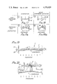
- FIG. 1 is a top plan view showing the tension and compression zones on a conventional prior art diaphragm
- FIG. 2 is a partially schematic sectional view taken along line 2--2 in FIG. 1 showing a typical stress curve for the diaphragm under pressure, superimposed over its actual movement;
- FIG. 3 is a top plan view similar to FIG. 1;
- FIG. 4 is a sectional view taken along line 4--4 in FIG. 3 showing the relation between a typical stress curve and the location of the strain gauges to monitor the results of such stress;
- FIG. 5 is a top plan view showing the tension and compression zones on a different prior art diaphragm
- FIG. 6 is a sectional view taken along line 6--6 in FIG. 5 showing the relation between a typical stress curve and the location of the strain gauges to monitor the results of such stress;
- FIG. 7 is a perspective view of a presently preferred embodiment of the improved diaphragm of the present invention.
- FIG. 8 is a sectional view taken along the line 8--8 in FIG. 7;
- FIG. 9 is a top plan view showing the tension and compression zones on the diaphragm of FIG. 7;
- FIG. 10 is a partially schematic sectional view taken along line 10--10 in FIG. 9 showing a stress curve for the improved diaphragm under pressure, superimposed over its actual movement;
- FIG. 11 is a sectional view of the improved diaphragm of FIG. 7 showing the relation between a stress curve and the location of the strain gauges to monitor the results of such stress;
- FIG. 12 is a partial sectional view showing a transducer incorporating the improved diaphragm of the present invention.
- FIG. 13 is a sectional view taken along line 13--13 in FIG. 12 which also shows an analogous Wheatstone bridge circuit
- FIG. 14 is an enlarged schematic sectional view showing a typical curve for a prior-art cantilever beam or diaphragm
- FIG. 15 is a top plan view of a cantilevered beam having recesses to displace the neutral plane according to an embodiment of the subject invention
- FIGS. 16a, 16b and 16c are sectional views taken along line 16--16 of the cantilevered beam of FIG. 15 showing the beam with a downward force applied to it and with an upward force applied to it;
- FIGS. 16d and 16e are enlarged schematic sectional views of the indicated portions of FIGS. 16b and 16c, respectively, showing the stress experienced by the beam;
- FIGS. 17 and 17a are schematic sectional view of a diaphragm in the nonpressurized and pressurized states, respectively;
- FIGS. 18 and 18a are schematic sectional views of a beam-diaphragm mechanism in the non-pressurized and pressurized states, respectively;
- FIGS. 19 and 20 are sectional views of a diaphragm and beam activated pressure transducer illustrating the tetra planar feature of my invention
- FIG. 21 is a top plan view of a diaphragm showing a preferred embodiment of a pattern of recesses and mesas to optimize the performance or the diaphragm;
- FIG. 22 is a sectional view taken along line 22--22 of FIG. 21, wherein the tension and compression forces on the upper surface of the diaphragm are illustrated by dotted lines;
- FIG. 23 is an enlarged plan view of the central portion of FIG. 21;
- FIG. 24 is a sectional view taken along line 24--24 of FIG. 23;
- FIG. 25 is a top plan view of a diaphragm showing a second preferred embodiment of my invention.
- FIG. 26 is a sectional view taken along line 26--26 of FIG. 25, wherein the tension and compression forces on the upper surface of the beam of the diaphragm activated pressure transducer are illustrated by dotted lines;
- FIG. 27 is a sectional view taken along line 27--27 of FIG. 25;
- FIG. 28 is a top plan view of yet another preferred embodiment of my invention.
- FIG. 29 is a sectional view taken along 29--29 of FIG. 28, wherein the tension and compression forces on the upper surface of the beam have been superimposed by dotted lines;
- FIG. 30 is a sectional view taken along line 30--30 of FIG. 28;
- FIG. 31 is a top view of a diaphragm according to a further embodiment of the subject invention.
- FIG. 32 is a section taken along line 32--32 in FIG. 31;
- FIG. 33 is a top view of a diaphragm according to a further embodiment of my invention.
- FIG. 34 is a section taken along line 34--34 in FIG. 33;
- FIG. 35 is a top view of a diaphragm according to a further embodiment of my invention.
- FIG. 36 is a section taken along line 36--36 in FIG. 35;
- FIG. 37 is a top view of a diaphragm according to a further embodiment of my invention.
- FIG. 38 is a section taken along the line 38--38 in FIG. 37;
- FIG. 39 is a top view of a diaphragm according to a further embodiment of my invention.
- FIG. 40 is a section taken along the line 40--40 in FIG. 39;
- FIG. 41 is a top view of a diaphragm according to a further embodiment of my invention.
- FIG. 42 is a section taken along the line 42--42 in FIG. 41;
- FIG. 43 is a top view of a diaphragm according to a further embodiment of my invention.
- FIG. 44 is a section taken along the line 44--44 in FIG. 43.
- FIG. 45 is a section taken along the line 45--45 in FIG. 43.
- FIGS. 1 and 2 illustrate a classical clamped edge diaphragm transducer including tensile strain gauges 20 and compressive strain gauges 22 mounted on the rearward surface of a circular, clamped edge diaphragm plate. More specifically, the tensile strain gauges 20 are mounted inside a boundary line 24 which circumscribes a tension zone 26 in which the diaphragm plate expands when subjected to pressure on the forward face of the plate. Compressive strain gauges 22 are sought to be mounted between line 24 and a line 28 which define or bound a compression zone 30 in which the diaphragm plate compresses and contracts when subjected to pressure on the forward face thereof.
- the interior spacer or housing wall 32 in effect serves as a barrier making it impossible to properly locate the compressive strain gauges 22.
- the interior spacer or housing wall 32 is integral with the clamped edge diaphragm and defines the circular line 28 which is the outer boundary of the compressive zone 30.
- the application of pressure to the front or forward face 34 of the diaphragm creates a strain in the diaphragm plate manifested by tension on the rear face 36 which reaches a maximum amplitude at point 38, and further manifested by compression of the plate which reaches a maximum compression amplitude point 40; that is, along the line 28 defined or immediately adjacent the interior spacer or housing wall 38.
- the inevitable spacer or housing wall 32 of the illustrated classical clamped edge diaphragm transducer structure thus renders it impossible to place the center of any sensor portion directly over the point of maximum compression amplitude 40.
- FIGS. 1 and 2 The showing of FIGS. 1 and 2 is juxtaposed on a reduced scale in FIGS. 3 and 4 to the showing, in FIGS. 5 and 6, of a conventional modification of the classical design described above with reference to FIGS. 1 and 2.
- the conventional modification according to FIGS. 5 and 6 provides a new or shifted maximum compression amplitude point 40 with the aid of a beveled edge 44 and a thickened spacer or housing wall at 46 changing the classical center plane 42 of the diaphragm plate shown in FIG. 2 and enabling positioning of the sensor portion 31 of the strain gauges 22 over the maximum stress point 40.
- equation (1) applies well to the classical clamped edge circular diaphragm of uniform thickness, wherein the center plane 42 divides the tension (T) and compression (C) stresses so that they are approximately equal on each side of such central plane (CP).
- the ratio of the thickness of the strain gauges to that of the diaphragm itself becomes significantly larger than in the case of higher pressure ranges, and the distance from the strain gauge to the center plane 42 (CP) becomes smaller, yielding a smaller and less stable output.
- the subject invention in effect provides the advantage shown in FIG. 6 without incurring the disadvantages associated with that conventional design.
- the subject invention provides as shown by way of example in FIGS. 7 to 11 an improved transducer diaphragm suitable for mounting around its periphery to a cylindrical spacer, such as the spacer or housing portion 32 shown in FIGS. 10 and 11.
- the diaphragm according to the current aspect of the invention, comprises a plate having an even back surface and a multilevel front surface, including an upper lever seen at 36 spaced from the back surface and a lower level shown at 50 and being closer to the back surface as seen in FIG. 8 than the upper level.
- the multilevel front surface includes at least two symmetrically positioned rear portions 54 at said lower level overlying a maximum strain amplitude section of the plate (see 40 in FIGS. 10 and 11).
- a strain gauge is mounted on the lower level of the multilevel front surface in, or extending into, each of the recesses 54, as seen in FIGS. 9 to 11.
- front surface is, of course, relative expressions and may, therefore, be interchangeably employed.
- the diaphragm just described is, according to a preferred embodiment of the subject invention, intended to measure pressure exerted against the mentioned back surface, and a strain gauge 31 is mounted in the recess portions 54 which overlie a maximum compression strain amplitude section 40 of the plate.
- the subject invention provides an improved transducer diaphragm comprising an outer peripheral portion 48 having a thickness greater than and separated by a boundary 52 from its central sensory portion 50.
- the boundary 52 defines at least one offset 54 of the central portion 50 extending into and partially bounded by the peripheral portion 48 for receiving a strain gauge 31 which can be mountable solely on the central sensory portion having a thickness smaller than the outer peripheral portion 48 and substantially overlying the location of maximum compression amplitude 40 of the diaphragm.
- the two offsets or notches 54 preferably are diametrically opposite from each other.
- the subject invention provides a method of making a transducer diaphragm employing a chemical etching process in combination with a masking technique to control the thickness and the diameter of the active area of the diaphragm, such diaphragm being designed for carrying strain gauges bonded on one face of the diaphragm within the inside edge of an annular support wall 32.
- the invention resides, more specifically, in the improvement comprising an etching process including the step of etching one face of the diaphragm to chemically mill out a central recess 50 which forms the active portion of the diaphragm as defined by an outer boundary and having a uniform thickness within the boundary with the diameter of the central recess appreciably less than the inner diameter of the annular support wall 32 to displace the active portion of the diaphragm inwardly from the inside edge of the annular support wall, and to chemically mill a peripheral notch 54 extending from the central recess 50 into the non-active portion of the diaphragm for receiving a compression-sensitive strain gauge 31.
- the etching step includes chemically milling a central recess 50 having a diameter which is essentially 75-80% of the inner diameter of the annular support wall 32.
- the etching step includes chemically milling a pair of peripheral notches displaced 180° apart.
- the mentioned etching step includes milling the central recess 50 on one face of the diaphragm and simultaneously milling the marginal edges 54 of the diaphragm on opposite faces of the diaphragm to achieve a uniform thickness for the central recess which is essentially one-half the thickness of the non-active portion or circular edge of the diaphragm.
- the chemical milling process is not limited to circular geometry and therefore lends itself to other geometrical patterns more advantageous in achieving an optimized diaphragm construction.
- the center plane is the neutral zone when pressure is applied within the range of the transducer (see FIG. 2).
- the distribution of the tension and compression strain and their amplitudes on the inside surface is well known as shown.
- the performance problems arise from the fact that it is physically impossible to place the compression gauges at the optimum location (see FIGS. 2 and 4). Other methods and designs have overcome this problem at increased unit cost (see FIGS. 5 and 6).
- Known photo-lithographic masking techniques are used to generate the dimensions and pattern desired from the applicable blueprint.
- the outline is etched from both sides to the center plane.
- the inside of the diaphragm is etched to a diameter 75-80% of the inside diameter of the supporting wall (spacer) to the center plane, and including in the illustrated embodiment two cut-outs at the periphery 180° apart to accommodate one end of each of the compression gauges (see FIG. 9).
- the ends of the compression gauges are then positioned in the neutral zone in the cut-outs near the edges (see FIG. 10).
- the center plane is shifted to a new location for that portion of the diaphragm which is in the center plane of the half thickness remaining (see FIGS. 10 and 11).
- the currently discussed aspect of the invention etches a decreased thickness portion or depression 50 within a boundary 52 which has one or more symmetrically spaced cut-outs 54.
- This causes a new neutral plane or center line 56 to create a maximum compression amplitude point which can be accurately and precisely monitored by the sensor portion 31 of a strain gauge 22 mounted on the rearward face of the plate and partially extending into the cut-outs or notches offset from the main central portion.
- this exemplary embodiment provides for both the compression and expansion strain gauges to be mounted within the depressed portion of the plate
- the unique application of the etching technique can be used to provide a multi-layer face on a diaphragm plate in a predetermined pattern such that certain of the sensors could be placed on the raised or thicker portion of the plate.
- this illustrated embodiment has the monitor spaces on the rearward face of the plate on the side opposite to where the pressure is being exerted, it is within the scope of the invention to mount the strain gauges on the level face of the plate in order to achieve the optimum monitoring position for the gauges.
- FIGS. 12 and 13 illustrate the structural mounting and electrical wiring typically employed with the present invention in combination with the improved plate-monitoring features described above.
- the four strain gauges having variable resistances R 1 to R 4 , are bonded at select locations as herein disclosed, and their leads are connected to form the classical Wheatstone bridge (WB) which translates the diaphragm deflection caused by the pressure (P) into a directly proportionate electrical analog signal (SIG) at a given excitation voltage (EXC) to the bridge.
- WB Wheatstone bridge
- the invention enables the strain gauge sensor to be placed on a diaphragm in an optimum position to measure the action or activity of the diaphragm when it is subjected to pressure directed against one side thereof.
- the invention preferably uses two sensors symmetrically positioned relative to the edge of the diaphragm where it connects at its outer boundary in order to accurately monitor the movement of both edges of the diaphragm.
- the invention provides two different ways of accurately measuring the same phenomenon; namely, the pressure being exerted against the surface of the diaphragm.
- it is possible to position the sensors directly over the portions of the diaphragm where maximum contraction and/or maximum expansion occur.
- FIG. 14 shows a fraction of a conventional diaphragm (see FIG. 2) or of a conventional cantilevered beam in which the central plane (CP) 42 is midway between the upper surface 36 and the lower surface 38, and in which the neutral stress plane (NP), as usual, is coincident with the central plane (CP).
- the neutral plane (NP) may be defined as the plane separating the tension and compression functional components of a diaphragm or beam. Reference may in this respect be had to the above mentioned U.S. Pat. No. 3,049,685, by W. V. Wright, which in its FIG. 3 shows the equal or non-amplifying compression and tension stress relationship in a conventional beam having coinciding central and neutral axes or planes.
- the subject invention provides a method of manufacturing a stress distribution plate for a pressure transducer having a central plane (CP) and a neutral stress plane (NP), and resides in the improvement comprising displacing the neutral stress plane (NP) from the central stress plane.
- the subject invention provides a stress distribution plate for a pressure transducer having a central plane (CP) and a neutral stress plane (NP), with the neutral stress plane (NP) being displaced from the central plane (CP).
- certain conditions may be changed or altered so that the resultant magnitude of the tension (T) and compression (C) are increased or amplified, providing an increased strain output which may be used advantageously as it occurs.
- T tension
- C compression
- we may choose to increase the total thickness dimension for greater stability, without sacrificing strain output for a given pressure range. Reference may in this respect be had to the above equation (1) and its accompanying text.
- both an increased strain output and an increase in the total thickness dimension of the diaphragm or stress distribution plate may be achieved according to preferred embodiments of the subject invention.
- FIGS. 15 and 16a there is shown a cantilevered beam 61 affixed to a wall support 62.
- the cantilevered beam 61 has an upper surface 63 having a plurality of recesses 64 therein.
- the recesses 64 on the cantilevered beam 61 or on a transducer diaphragm are sufficiently frequent to justify use of the adjective "lacunose" for the surface 63 or generally for the beam 61 or equivalent diaphragm.
- lacunae in this respect stems from the Latin word lacunosus, meaning "full of lacunae.” Lacunae, on the other hand, are defined as recesses, spaces, cavities and depressions. By way of illustration, reference may, in this respect, be had to the lacunaria on the inside of the cupola of the Pantheon in Rome and the coffer vault of the Basilica of Constantine in Istanbul, characterized by a multitude of depressed panel regions.
- the subject invention and its embodiments are not limited to such architectural forms, as may, for instance, be seen in the further course of the subject disclosure.
- the lacunae 64 or the lacunose nature of the surface 63 or beam 61 effect a displacement of the neutral stress plane (NP) relative to the central plane (CP) in a beam or equivalent diaphragm, with corresponding changes in the tension (T) and compression (C) component relationships.
- isogrid structure may also be employed in connection with stress distribution plates, beams and diaphragms of the subject invention (cf. Paul Slyth, The Isogrid, King of Lightweight Design, MACHINE DESIGN, Apr. 19, 1973, pp. 102-107).
- the neutral stress plane (NP) is shifted away from the central plane (CP) toward the lower surface 65, to be located between the central plane and such lower surface.
- the neutral plane (NP) is displaced from the central plane (CP) by a distance ⁇ M.
- strain gauges are bonded to the diaphragm or beam 61 in coincidence with regions or isthmi located between lacunae 64 of the lacunose surface region 61.
- This distinguishes the illustrated preferred embodiments from such proposals as advanced in U.S. Pat. No. 3,520,191 by Hsai-Si Pien, and U.S. Pat. No. 4,103,273, by H. W. Keller, where strain gauges are bonded in coincidence with recesses or depressions.
- diaphragms, beams and stress distribution plates can now be manufactured in multiples from appropriate thicknesses of sheetstock or metal, employing photo-lithographic masking techniques and chemical milling to selectively etch any predetermined pattern of equal or unequal geometry on each side or simultaneously on both sides of the center plane (CP) of the material. Simultaneous etching on both sides of the material may proceed at the same rate.
- Additional features of my invention concern the discovery or invention of designs and patterns for diaphragms and beam which result in a displacement geometry, with pressure or force, of a tetra planar configuration which intrinsically tends to generate nearly equal stress levels of the compression and tension components of the system, though being not necessarily restricted to such a feature.
- the magnitude of stress levels may be graphically represented by angles shown in FIGS. 17, 17a, 18 and 18a.
- FIGS. 17 and 17a diagrammatically show a diaphragm 57 clamped to an interior wall 62, without pressure applied and with pressure applied, respectively.
- FIGS. 18 and 18a show a beam 68 abutting and activated by a diaphragm 67. Such diaphragm and beam 68 are shown without external pressure applied (FIG. 18) and with external pressure applied (FIG. 18a), respectively.
- the angle a is equal to twice the angle b in FIG. 17a. Therefore, the tension output (T) is nominally twice the compression output (C) and thus increases the bridge impedance directly proportional to pressure or force when a Wheatstone bridge circuit is employed as the sensing agency of the strain gauge components.
- the compression sensing elements must be mounted on the upper side of the beam 68, and the tension sensing elements directly opposite on the lower side of the diaphragm 67. Also, the compression sensing elements and the tension sensing elements nominally have equal output. In terms of subsequent processing or even in terms of manufacture, it is, however, frequently not expedient to mount the different gauges on different sides or to mount the lower gauges in a relatively inaccessible location. This is particularly disadvantageous when high temperature processes are required, such as welding, brazing or heat treating, in the manufacture or processing of the transducer.
- the problems illustrated with the aid of FIGS. 17a and 18a are overcome by management of the stress and strain locations, preferably by means of properly located relatively rigid and compliant sections or areas in a geometrical manner whereby stress concentration locations are optimized, the tension and compression strain gauges are all on one side of the beam structure or diaphragm, the compression and tension outputs are equalized for the maintenance of an ideally stable bridge impedance condition throughout the entire pressure/force range of the transducer.
- a further important feature includes the shifting of the neutral stress plane (NP) away from the sensing elements or strain gauges and the central plane (CP) whereby to effect a calculated mechanical advantage or amplification providing an increased transducer output or alternatively allowing an increase in beam or diaphragm thickness for increased stability, without the type of output loss penalty incurred with prior-art devices when the beam or diaphragm thickness was increased.
- the structures of my invention are more rigid and stable, enhancing the ultimate performance and stability of my transducers.
- my beams and diaphragms present a lighter structure, which improves the frequency response characteristic of the beam or diaphragm because of a reduced mass.
- embodiments of my invention permit very significant mass reductions because of the relatively high stiffness afforded by lacunose or isogrid-type structures of the kind herein disclosed.
- a further advantage of my shift of the neutral plane relative to the central plane will appear from FIGS. 19 and 20.
- FIGS. 19 and 20 Sample graphic illustrations of tetra planar beams and diaphragms according to an aspect of my invention are shown in FIGS. 19 and 20.
- the angle a is made equal to the angle b, rather than being twice as high as in FIG. 17a.
- the beam, diaphragm or plate shown in FIGS. 19 and 20 has a tetraplanar configuration, with a portion of the plate between a first plane and a second plane of the tetraplanar configuration sloping at like angles a and b to these first and second planes. Since the two angles a and b are nominally equal, the compression (C) and the tension (T) components are nearly equal.
- the double end supported beam shown in FIG. 20 may, if desired, be formed as a single end supported or cantilevered beam.
- the fact that the angle a is equal to the angle b in the embodiments of FIGS. 19 and 20 and in the single end supported beam just mentioned provides for an equalization of the compression and tension outputs to maintain a stable bridge impedance condition throughout the pressure/force range of the transducer.
- my preformed diaphragm and beam structures also provide for a shifting of the neutral plane (NP) relative to the central plane (CP) whereby the mechanical advantage or amplification explained above with the aid of FIGS. 16d and 16e is again realized.
- the tension and compression sensing elements or strain gauges may be located on the upper surface of the diaphragm or beam.
- FIGS. 21 to 30 there are shown therein three preferred embodiments of my invention. For the sake of simplicity, all three will first be discussed jointly.
- a stress distribution plate or diaphragm 71 having a pattern of mesas 72 and recesses 73 formed on one surface thereof is shown supported by conventional means, such as an edge clamping spacer or housing 32.
- strain gauges 74 Overlying the surface of the plate at predetermined areas of the mesas are a plurality of strain gauges 74 for measuring the tension and compression forces in these predetermined areas.
- the areas whereon the strain gauges are located are thoses wherein the compression and tension forces are equal and are a maximum so as to maximize the output of the strain gauges and to have them in balance in the Wheatstone bridge, which is the customary manner of electrically connecting the strain gauges so as to measure the pressure.
- the plates shown in FIGS. 25 to 30 are of the beam type wherein the force transmitted to the plate 71 is transferred from a pressure sensing element 76 to the plate 71 by means fo a force transfer beam or rod 77.
- the plates in the beam-type pressure transducers shown are mounted in a conventional manner within the pressure transducer housing.
- the plates 71 of my invention may be mounted in a manner well known to those having ordinary skill in the art within conventionally designed pressure transducer housings and are electrically connected in a manner also well known to those having ordinary skill in the art for monitoring of the electrical output of the strain gauges as a function of the force applied to the diaphragm plate.
- the plate 71 is provided with a first surface 63 and a second surface 65 at opposite sides of a central plane (CP) and the plate 71, and with a predetermined pattern of mesas and recesses 72 and 73 on the first surface displacing the neutral stress plane (NP) from the central plane.
- the mesas 72 are preferably provided with surface areas located on the first surface 63 to produce maximum areas of tension and compression in predetermined areas of the first surface 63 when the plate 71 is under stress.
- the predetermined pattern of mesas 72 and recesses 73 is provided symmetrically to a central axis of the plate 71, as seen in FIG. 23 et seq.
- the predetermined pattern may be provided with recesses 73 displaced from a central area 78 of the plate 71.
- Such displaced recesses 73 preferably are provided symmetrically about an axis normal to the central axis.
- the predetermined pattern may be provided with identical recesses 73 and mesas 72 on both sides of the central axis of the plate 71.
- the predetermined pattern of mesas and recesses is formed by a chemical etching process.
- a method according to a preferred embodiment of the subject invention of making a stress distribution plate for use in a pressure transducer resides in the improvement comprising, in combination, the steps of forming a plate 71 with an upper surface 63 and with a lower surface 65 extending parallel to the upper surface, providing a neutral pressure plane coincident with the central plane, and concentrating the stress experienced by the plate to predetermined areas when the plate is flexed, by removing predetermined portions from the plate at the upper surface 63 until the neutral plane (NP) is displaced from the central plane (CP).
- the predetermined portions just referred to are preferably removed by chemical etching such predetermined portions away from the plate at the upper surface 63.
- the currently discussed aspect of my subject invention thus provides means including the strain gauge plate 71 having a plurality of recesses 73 in the first surface 63 for displacing the neutral stress plane (NP) from the central plane (CP).
- Strain gauge means or elements 74 are mounted on the first surface 63 between the recesses 73.
- the strain gauge elements 74 may be connected in a Wheatstone bridge arrangement and may be individually mounted between recesses 73 on the first surface 63.
- FIGS. 31 et seq. illustrate further embodiments of my invention.
- the expression "transducer diaphragms" is frequently employed. As indicated above, such expression is, however, intended to be broad enough to extend to beams and stress distribution plates.
- the transducer diaphragm 81 shown in FIGS. 31 and 32 may be edge clamped as shown at 82 in FIG. 32.
- the diaphragm 81 has or is provided with a recess 83 encompassed by a circumferential edge region 84 of the diaphragm.
- a promontory 85 projects from the edge region 84 into the recess 83 and is integral with the diaphragm 81.
- a strain gauge 74 is bonded to the diaphragm 81 in coincidence with the promontory. As seen in FIGS. 31 and 32, the strain gauge 74 may extend from coincidence with the promontory 85 into coincidence with part of the edge region 84 adjacent the promontory.
- the promontory 85 has the form of a peninsula located in the recess 83 and connected to the edge region 84 by an isthmus 86.
- the strain gauge 74 is bonded to the diaphragm in coincidence with the isthmus 86 and with adjacent portions of the peninsula at 85 and of the edge region 84.
- the center of the sensor 31 may extend along the isthmus 86.
- a raised island 87 may be located in the recess 83, spaced from the promontory 85 and from the edge region 84 and integral with the diaphragm 81.
- a further strain gauge 74 is bonded to the diaphragm in coincidence with the island 87.
- the spaced island 87 may be provided with an isthmus 88 interconnecting two main portions of the island.
- a further strain gauge 74 or a center portion 31 thereof is bonded to the diaphragm in coincidence with the isthmus 88 of the spaced island 87.
- a second promontory 91 separate from the first promontory 85 and projecting from the edge region 84 into the recess 83 diametrically opposite from the first promontory 85.
- the second promontory 91 is integral with the diaphragm 81.
- first strain gauge 74 bonded to the diaphragm in coincidence with the first promontory 85
- second strain gauge 74 bonded to the diaphragm in coincidence with the second promontory 91.
- This second strain gauge also may extend from coincidence with the second promontory 91 into coincidence with a second part of the edge region 84 adjacent such second promontory.
- the second promontory 91 also may have the form of a second peninsula located in the recess 83, spaced from the first peninsula 85, and connected to the edge region 84 by a second isthmus 92.
- the second strain gauge 74 or a central sensor portion thereof may then be bonded to the diaphragm 81 in coincidence with the second isthmus 92 and adjacent portions of the second peninsula 91 and edge region 84.
- the raised island 87 is spaced from both the first and second promontories 85 and 91, in addition to being spaced from the circumferential edge region 84 of the diaphragm.
- first and second raised islands 87 and 94 may be provided at opposite side of, and spaced from, the first and second promontories 85 and 91.
- the islands 87 and 94 are also spaced from each other and integral with the diaphragm 81.
- a third strain gauge 74 is bonded to the diaphragm in coincidence with the first island 87 and a fourth strain gauge is bonded to the diaphragm in coincidence with the second island 94.
- the second island 94 also may have an isthmus 95 interconnecting two main portions of this second island, and the fourth strain gauge 74 may be bonded to the diaphragm in coincidence with such second insular isthmus 95.
- FIGS. 31 and 32 ideally locates stress concentrations enabling all strain gauges 74 to be placed on the same side of the diaphragm 81 and equalizing the compression and tension outputs to maintain a nearly stable bridge impedance condition throughout the pressure/force range of the diaphragm or transducer. Such embodiment also provides for a displacement of the neutral stress plane (NP) away from the strain gauges 74 and from the central plane (CP) towards the lower surface of the diaphragm as seen in FIG. 32.
- the embodiment of FIGS. 31 and 32 thus provides for an amplification of tension (T) and compression (C) components as described above (see FIGS. 16d and 16e).
- the transducer diaphragm 97 shown in FIGS. 33 and 34 includes a central portion 98 having first radial projections 99, and a circumferential edge region 84 having second radial projections 100 and encompassing the central portion 98 and first radial projections 99.
- a recess 83 in the diaphragm 97 separates the central portion 98 and first radial projections 99 from the edge region 84 and second radial projections 100.
- Strain gauges 74 are bonded to the diaphragm 97 in coincidence with the projections 99 and 100.
- the recess 83 extends perimetrically about the central portion 98 and first radial projections 99 and inside of the edge region 84 and second radial projections 100.
- the recess 83 may have a sinuous configuration as more clearly seen in FIGS. 35 and 36.
- FIGS. 35 and 36 show a diaphragm 102 in accordance with a further embodiment of my subject invention, in which the first and second projections 99 and 100 of the central portion 98 and circumferential edge region 84, respectively, are interdigitated with each other which, incidentally, is also the case in the embodiment of FIGS. 33 and 34.
- the central portion 98 and first radial projections 100 form a star pattern in the recess 83.
- the second radial projections 100 are complementary with such star pattern.
- the recess 83 may be provided by etching material away from the diaphragm 102.
- FIGS. 37 to 40 provide diaphragms 104 and 105 having a circumferential edge region 84 and a raised central portion 106 spaced inwardly from the circumferential edge region and integral with the diaphragm.
- Diametrically opposed first and second isthmi 107 and 108 interconnect the edge region 84 with the inwardly spaced central portions or island 106.
- Diametrically opposed and mutually spaced third and fourth isthmi 109 and 110 are provided in the central portion 106 and are distinct from the first and second isthmi 103 and 108.
- First, second, third and fourth strain gauges 74 are bonded to the diaphragm in coincidence with the first, second, third and fourth isthmi 107, 108, 109 and 110, respectively. This in similarity to the embodiments of FIGS. 33 to 36 where strain gauges are individually bonded to or in coincidence with projections 99 and 100.
- the first and second isthmi 107 and 108 extend along a diameter of the diaphragm 104.
- the third and fourth isthmi 109 and 110 of the diaphragm 104 extend in parallel to the latter diameter.
- the first and second isthmi 107 and 108 are formed with the aid of first and second recesses 112 and 113 provided in the diaphragm 104 or 105 between the edge region 84 and the central portion or peninsula 106.
- the third and fourth isthmi 109 and 110 in the diaphragm 104 are provided with the aid of a third recess 114 extending between the third and fourth isthmi 109 and 110 in and through a center of the central portion 106 which is raised relative to the recesses 112 and 113.
- the third isthmus 109 is also bounded by the first recess 112
- the fourth isthmus 110 is also bounded by the second recess 113.
- the third recess 114 is extended between the first and second recesses 112 and 113 to provide the third isthmus 109 with the aid of the first recess 112 and to provide the fourth isthmus 110 with the aid of the second recess 113.
- the third and fourth isthmi 109 and 110 may be provided with the aid of, or may be bounded by, third and fourth recesses 116 and 117 provided and extending in the central portion 106 inside of the first and second recesses 112 and 113.
- FIGS. 41 to 45 are related or bear a strong resemblance to the embodiment shown in FIGS. 15 to 16e having lacunose surface regions for shifting the neutral plane (NP) away from the central plane (CP) and away from the beam or diaphragm surface to which the strain gauges 74 are bonded.
- FIGS. 15 and 41 to 45 provide a plurality of distinct recesses 64 in the beam or diaphragm and arrange such recesses 64 to provide in the beam or diaphragm distinct first, second, third and fourth isthmi 123, 124, 125 and 126 between adjacent pairs of recesses 64.
- Distinct first, second, third and fourth strain gauges 74 are bonded, respectively, to the first, second, third and fourth isthmi 123, 124, 125 and 126.
- further recesses 128 may be provided in the diaphragm 120 in addition to the recesses 64 providing the first, second, third and fourth isthmi 123 to 126.
- as many further recesses 128 may be provided as required to form a lacunose beam or diaphragm region displacing the neutral plane (NP) relative to the central plane (CP).
- the further recesses 128 and the recesses 64 providing the isthmi 123 to 126 are located in an annular region 129 encompassing a central region 130 on the diaphragm 121.
- at least some of the further recesses 128 may be interconnected by yet further recesses or interconnecting grooves in the diaphragm 121.
- one of the distinct recesses 64 is a central recess in a central region 131 of the diaphragm.
- the other of the distinct recesses 64 are situated around the central recess in a planetary manner between such central recess or central region 131 and a circumferential edge region 84 of the diaphragm.
- the first isthmus 123 may then be located between the central recess and a first one of the other recesses, and the second isthmus 124 may be located between the central recess and a second one of the other recesses.
- the third isthmus 125 may be located between a third and fourth of the other recesses, and the fourth isthmus 126 between a fifth and sixth of the other recesses 64.
- Two of the isthmi preferably are located, respectively, between two different pairs of the other recesses 64, as seen, for instance, at the right and left-hand sides of FIG. 43.
- the apertures 64 in FIGS. 41 to 45 and the apertures 128 in FIGS. 41 and 42 may be viewed as providing a lacunose surface region on the diaphragm 121 or 122, with strain gauges bonded to the diaphragm in coincidence with regions located between lacunae on the lacunose surface region.
- isthmi 123 to 126 are formed between lacunae of the lacunose surface region, and strain gauges are bonded to the diaphragm 121 or 122 in coincidence with such isthmi.
- Recesses 132 as indicated in FIG. 41 may be provided to interconnect lacunae of the lacunose surface region.
- Such lacunae 64 and 128, and any recesses 132 preferably are provided by selectively etching material from the diaphragm.
- the diaphragm 71 has a circumferential edge region 84 and a raised central portion 78 spaced inwardly from the circumferential edge region and integral with the diaphragm 71.
- a first pennisula 131 extends from the edge region 84 towards, but is spaced from, the central portion 78 and is connected to the edge region 84 by a first isthmus 123.
- a second peninsula 132 extends from the edge region 84 towards, but is spaced from, the central portion 78 opposite the first peninsula 131, and is connected to the edge region 84 by a second isthmus 124.
- a third peninsula 133 extends from the central portion 78 towards, but is spaced from, the edge region 84 and is connected to the central portion 78 by a third isthmus 125.
- a fourth peninsula 134 extends from the central portion 78 towards, but is spaced from, the edge region 84 opposite the third peninsula 133, and is connected to the central portion 78 by a fourth isthmus 126.
- First, second, third and fourth strain gauges 74 are bonded to the diaphragm 71 along the first, second, third and fourth isthmi 123, 124, 125 and 126, respectively.
- the first and third peninsulas 131 and 133 are preferably arranged in a first pair 136 of adjacent but distinct peninsulas.
- the second and fourth peninsulas 132 and 134 are preferably arranged in a second pair 134 of adjacent but distinct peninsulas.
- isthmi may be provided between the central portion 78 and edge region 84.
- fifth and sixth isthmi 141 and 142 may extend from the edge region 84 to the central portion 78 along opposite side of the first pair 136.
- seventh and eighth isthmi 143 and 144 may extend from the edge region 84 to the central portion 78 along opposite sides of the second pair 137.
- the additional isthmi 141 to 144 serve to isolate the strain gauges 74 from externally induced stresses, such as hoop stresses due to lateral depression of the diaphragm, and stresses induced in the mounting process by the tightening of fasteners and otherwise.
- a first curved recess 146 may be located in the diaphragm 71 between the edge region 84 and the central portion 78 and may extend from the fifth isthmus 141 to the seventh isthmus 143.
- a second curved recess 148 may be located in the diaphragm 71 between the edge region 84 and the central portion 78 and may extend opposite the first curved recess 148 from the sixth isthmus 142 to the eighth isthmus 144.
- FIG. 23 shows a fraction of the diaphragm 71 shown more fully in FIGS. 21 and 22, or may be viewed as an application of the teachings of the embodiment of FIGS. 21 and 22 to a beam or other stress distribution plate 149.
- the neutral stress plane (NP) is displaced away from the central plane (CP) and from the strain gauges 74 to provide a considerable mechanical advantage (MA) or amplification of tension (T) and compression (C) components.
- MA mechanical advantage
- T tension
- C compression
- ⁇ M distance between the center plane (CP) and the neutral plane (NP) must be determined. This can be done by sectioning the beam or diaphragm normal to the center plane (CP) and the strain gauge at the point of maximum compression (C) or tension (T), or apex, and dividing the cross sectional area so that the two divided areas are equal on both sides of this line or plane.
- the section of a beam is defined by its outline. However, in the case of a diaphragm, the section must be limited to a distance approximately equal to the active length of the strain gauge on both sides of the strain gauge, for the purposes of the subject calculation.
- the distance of the central plane (CP) from the right-hand side of the section shown in FIG. 24 was equal to t/2 or 0.076 mm.
- the effective area of the beam or diaphragm to the left of the central plane (CP) as seen in FIG. 24 was 0.039 mm 2 .
- the area to the right of the central plane (CP) as seen in FIG. 24 was 0.138 mm 2 , providing for a total sectional area of 0.177 mm 2 and a value of 0.088 mm 2 for half that area.
- l active length as defined above.
- ⁇ 1 strain of conventional diaphragm/beam
- t 1 thickness of uniform-thickness diaphragm
- t 2 maximum thickness (previously t) of diaphragm according to invention.
- the mechanical amplification is even more substantial if the total thickness of a diaphragm according to the subject invention has been substantially increased over the thickness of a uniform-thickness prior-art diaphragm. For instance, if we assume that the above value of t of 0.152 mm represents twice the thickness of a given uniform-thickness diaphragm, we may find with the aid of equation (4) that the mechanical advantage (MA) or amplification is eqyal to 2.736. In practice, amplifications by a factor of more than three are readily attainable.
- first, second, third and fourth isthmi 123, 124, 125 and 126 are provided in the beam or diaphragm, each having a longitudinal dimension.
- the first, second, third and fourth isthmi 123 to 126 are arranged to extend along their longitudinal dimensions in series between opposite marginal diaphragm or beam regions 151 and 152.
- First, second, third and fourth strain gages 74 are bonded, respectively, to the first, second, third and fourth isthmi 123, 124, 125 and 126, as seen in FIG. 25.
- the isthmi 123, 124, 125 and 126 may extend with their longitudinal dimensions in parallel to a diaphragm diameter extending between opposite marginal diaphragm regions.
- a first pair 136 of isthmi 123 and 125 having longitudinal dimensions, is provided in the beam or diaphragm.
- a second pair 137 of isthmi 124 and 126 having longitudinal dimensions, is also provided in the beam or diaphragm.
- the first and second pair of isthmi 136 and 137 are arranged to extend with their longitudinal dimensions in series between opposite marginal diaphragm or beam regions 151 and 152.
- First, second, third and fourth strain gauges 74 are bonded, respectively, to the first, second, third and fourth isthmi 123 to 126.
- the longitudinal dimensions of the isthmi 123 and 125 in the first pair 136 may be arranged in parallel, while the longitudinal dimensions of the isthmi 124 and 126 in the second pair 137 may also be arranged to extend in parallel with each other and, if desired, in parallel with the longitudinal dimensions of the isthmi in the first pair 136.
- the stress distribution plates, beams or diaphragms according to my invention have a wide range of utility, including the transducer field, in a wide range of loads, including high, medium and low pressure applications.
- the principles of my invention enable work at extremely low pressures, such as pressures below one-half pound per square inch (psi) and even as low as one-tenth psi and less.
- the patterns of mesas and recesses 72 and 73 or peninsulas and isthmi may, and preferably should, be symmetrical relative to, or identical on both sides of, a central axis which, for instance, may be a central axis of a diaphragm or stress distribution plate, or a longitudinal or transverse axis of a beam, depending on configuration and application. Accordingly, the patterns of mesas and recesses or peninsulas and isthmi typically would be the same on both right and left hand sides of FIGS. 21 and 22; that is, either the same as shown for the left-hand side or the same as shown and presently to be discussed for the right-hand side of FIGS. 21 and 22.
- the presently discussed right-hand side of the illustrated stress distribution plate or beam also has its neutral stress plane (NP) displaced from the central plane (CP), as previously disclosed with respect to FIG. 24, for instance.
- the predetermined pattern shown in the right-hand side of FIGS. 21 and 22 includes apertures 156 penetrating the plate or diaphragm 71 through the first and second surfaces 63 and 65 or, in other words, through its entire thickness.
- the apertures 156 in particular penetrate the plate or diaphragm adjacent the mesas and recesses in the first surface 63.
- This feature may also be applied to the recesses 146 and 148 which, accordingly, may be partially or fully replaced by through holes or apertures 157 and 158 penetrating the thickness of the plate or diaphragm 71 through the first and second surfaces 63 and 65.
- the recesses 73 may be reduced to narrower recesses 173 defining the isthmi 124 and 126 of the peninsulas 132 and 134.
- the plate or diaphragm structure is provided by etching, then the plate or diaphragm would be etched through its thickness at the apertures 156 to 158, but would be etched for only a certain portion of its thickness from the first surface 63 for a provision of the recesses 173, as best seen in FIG. 22.
- the apertures 156 and 158 could be provided by simultaneous etching from both surfaces.
- one or more grooves or recesses 161 may be provided in the second surface 65, so as to interconnect the apertures 156.
- the stress distribution plate or diaphragm 71 may comprise an edge region 84 and a raised portion 78 spaced from the edge region and integral with the plate 71.
- a first peninsula 132 extends from the edge region 84 to the spaced portion 78 and is connected to the edge region 84 by a first isthmus 124.
- a second peninsula 134 extends from the spaced portion 78 to the edge region 84 and is connected to the spaced portion 78 by a second isthmus 126.
- Mutually spaced apertures 156 penetrate the plate 71 adjacent the peninsulas 132 and 134 and isthmi 124 and 126.
- a third isthmus interconnects the first peninsula 132 with the spaced portion 78, while a fourth isthmus interconnects the second peninsula 134 with the edge region 84.
- These third and fourth isthmi are formed by or extend adjacent the grooves or recesses 161.
- the previously mentioned lateral isthmi 143 and 144 may be omitted for extreme sensitivity or may be retained for high stability. In the latter case, the previously mentioned apertures 157 and 158 may be provided between and through the first and second plate surfaces 63 and 65.
- the third and fourth isthmi provide fulcrums adjacent the grooves or recesses 161, as shown at 162 in FIG. 2.
- Such fulcrum mounts offer a minimum of resistance to movement of the central region of the plate or diaphragm in response to pressure.
- a pressure sensing element such as a diaphragm of the type shown at 76 in FIGS. 26 and 29, may be employed, in which case the plate 71 is a diaphragm in a figurative sense.
- the diaphragm 76 and force transfer rod 77 shown in FIGS. 26 and 29 may be employed for picking up pressure and transferring such picked-up pressure force to the central portion 78 of the stress distribution plate 71 shown in FIGS. 21 and 22.
- the subject invention and embodiments thereof meet the initially mentioned objectives in an advantageous and relatively low-cost manner.
Abstract
Description
ΔM=t/2-A/2/l (2)
MA=ε.sub.2 /ε.sub.1 (3)
MA=t.sub.2 /t.sub.1 +2ΔM/t.sub.1 (4)
Claims (52)
Priority Applications (2)
| Application Number | Priority Date | Filing Date | Title |
|---|---|---|---|
| US06/110,024 US4376929A (en) | 1976-12-27 | 1980-01-07 | Optimized stress and strain distribution diaphragms |
| US06/419,352 US4507170A (en) | 1980-01-07 | 1982-09-17 | Optimized stress and strain distribution diaphragms |
Applications Claiming Priority (2)
| Application Number | Priority Date | Filing Date | Title |
|---|---|---|---|
| US05/754,251 US4133100A (en) | 1976-12-27 | 1976-12-27 | Method of making diaphragm of optimized stress and strain distribution |
| US06/110,024 US4376929A (en) | 1976-12-27 | 1980-01-07 | Optimized stress and strain distribution diaphragms |
Related Parent Applications (2)
| Application Number | Title | Priority Date | Filing Date |
|---|---|---|---|
| US06001310 Division | 1979-01-05 | ||
| US06006086 Continuation-In-Part | 1979-01-24 |
Related Child Applications (1)
| Application Number | Title | Priority Date | Filing Date |
|---|---|---|---|
| US06/419,352 Division US4507170A (en) | 1980-01-07 | 1982-09-17 | Optimized stress and strain distribution diaphragms |
Publications (1)
| Publication Number | Publication Date |
|---|---|
| US4376929A true US4376929A (en) | 1983-03-15 |
Family
ID=26807628
Family Applications (1)
| Application Number | Title | Priority Date | Filing Date |
|---|---|---|---|
| US06/110,024 Expired - Lifetime US4376929A (en) | 1976-12-27 | 1980-01-07 | Optimized stress and strain distribution diaphragms |
Country Status (1)
| Country | Link |
|---|---|
| US (1) | US4376929A (en) |
Cited By (24)
| Publication number | Priority date | Publication date | Assignee | Title |
|---|---|---|---|---|
| FR2532746A1 (en) * | 1982-09-03 | 1984-03-09 | Endress Hauser Gmbh Co | FLEXION SPRING |
| US4628296A (en) * | 1983-06-13 | 1986-12-09 | Tokyo Electric Co., Ltd. | Load cell |
| US4852581A (en) * | 1987-12-14 | 1989-08-01 | Medex, Inc. | Pressure transducer with conductive polymer bridge |
| US4974596A (en) * | 1987-12-14 | 1990-12-04 | Medex, Inc. | Transducer with conductive polymer bridge |
| EP0410014A1 (en) * | 1989-07-22 | 1991-01-30 | Hottinger Baldwin Messtechnik Gmbh | Pressure sensor and method for the calibration of pressure sensors |
| US5092177A (en) * | 1989-07-27 | 1992-03-03 | Sextant Avionique | Device for measuring the deformations of a diaphragm |
| US5209118A (en) * | 1989-04-07 | 1993-05-11 | Ic Sensors | Semiconductor transducer or actuator utilizing corrugated supports |
| US5481920A (en) * | 1992-11-17 | 1996-01-09 | Agency Of Industrial Science & Technology | Fluid pressure measuring sensor using strain gauges |
| WO2000012989A1 (en) * | 1998-08-31 | 2000-03-09 | Maxim Integrated Products, Inc. | Piezoresistive pressure sensor with sculpted diaphragm |
| US6140143A (en) * | 1992-02-10 | 2000-10-31 | Lucas Novasensor Inc. | Method of producing a buried boss diaphragm structure in silicon |
| US20040083825A1 (en) * | 2002-11-05 | 2004-05-06 | Tanita Corporation | Diaphragm type load detection sensor, load detection unit and electronic scale using same |
| US20050050958A1 (en) * | 2003-09-05 | 2005-03-10 | Toshikatsu Miyake | Load sensor |
| US20070017303A1 (en) * | 2003-04-04 | 2007-01-25 | Omron Corporation | Flow rate-measuring device |
| US20090007680A1 (en) * | 2007-07-03 | 2009-01-08 | Kurtz Anthony D | High pressure transducer having an H shaped cross-section |
| US20090205434A1 (en) * | 2008-02-14 | 2009-08-20 | Kulite Semiconductor Products, Inc. | Low differential pressure transducer |
| US20090205433A1 (en) * | 2008-02-14 | 2009-08-20 | Kulite Semiconductor Products, Inc. | Low differential pressure transducer |
| US7806001B1 (en) * | 2007-06-05 | 2010-10-05 | Orbital Research Inc. | Multi-diaphragm pressure sensors |
| US20100326199A1 (en) * | 2008-02-14 | 2010-12-30 | Kulite Semiconductor Products, Inc. | Low differential pressure transducer |
| US7878069B2 (en) | 2009-05-04 | 2011-02-01 | Kulite Semiconductor Products, Inc. | Torque insensitive header assembly |
| CN102353388A (en) * | 2011-06-16 | 2012-02-15 | 上海理工大学 | Method for optimizing structure size of multi-directional force sensor |
| JP2018049037A (en) * | 2018-01-04 | 2018-03-29 | 株式会社東芝 | Pressure sensor, microphone, ultrasonic sensor, blood pressure sensor, and touch panel |
| EP3392633A1 (en) | 2017-04-19 | 2018-10-24 | Huba Control Ag | Pressure transducer |
| US20190120781A1 (en) * | 2016-03-31 | 2019-04-25 | Kyocera Corporation | Stress sensor |
| US20220056902A1 (en) * | 2019-07-09 | 2022-02-24 | Xi'an Jiao Tong University | Device and method for monitoring oil pressure and gas pressure of diaphragm compressor |
Citations (14)
| Publication number | Priority date | Publication date | Assignee | Title |
|---|---|---|---|---|
| US3049685A (en) * | 1960-05-18 | 1962-08-14 | Electro Optical Systems Inc | Electrical strain transducer |
| US3325761A (en) * | 1965-01-11 | 1967-06-13 | Electro Optical Systems Inc | Pressure transducer |
| US3335381A (en) * | 1965-07-06 | 1967-08-08 | Stratham Instr Inc | Duplex flexure for force transducer |
| US3341794A (en) * | 1965-07-26 | 1967-09-12 | Statham Instrument Inc | Transducers with substantially linear response characteristics |
| US3568124A (en) * | 1967-06-01 | 1971-03-02 | Kistler Instrumente Ag | Piezoresistive force- and pressure-measuring element |
| US3712123A (en) * | 1971-01-07 | 1973-01-23 | Blh Electronics | Compound-plate strain gage transducer |
| US3739315A (en) * | 1972-05-18 | 1973-06-12 | Kulite Semiconductors Prod Inc | Semiconductor transducers having h shaped cross-sectional configurations |
| US3838379A (en) * | 1972-01-12 | 1974-09-24 | Philips Corp | Pressure transducer for liquids or gases |
| US3869906A (en) * | 1972-12-26 | 1975-03-11 | Bofars Ab | Element applicable as or in a transducer (load cell) |
| US3909924A (en) * | 1974-03-27 | 1975-10-07 | Nat Semiconductor Corp | Method of fabrication of silicon pressure transducer sensor units |
| US4016644A (en) * | 1974-03-18 | 1977-04-12 | Kulite Semiconductor Products, Inc. | Methods of fabricating low pressure silicon transducers |
| US4050049A (en) * | 1976-02-09 | 1977-09-20 | Signetics Corporation | Solid state force transducer, support and method of making same |
| US4071838A (en) * | 1976-02-09 | 1978-01-31 | Diax Corporation | Solid state force transducer and method of making same |
| US4144516A (en) * | 1976-03-29 | 1979-03-13 | Aine Harry E | Solid state transducer and method of making same |
-
1980
- 1980-01-07 US US06/110,024 patent/US4376929A/en not_active Expired - Lifetime
Patent Citations (14)
| Publication number | Priority date | Publication date | Assignee | Title |
|---|---|---|---|---|
| US3049685A (en) * | 1960-05-18 | 1962-08-14 | Electro Optical Systems Inc | Electrical strain transducer |
| US3325761A (en) * | 1965-01-11 | 1967-06-13 | Electro Optical Systems Inc | Pressure transducer |
| US3335381A (en) * | 1965-07-06 | 1967-08-08 | Stratham Instr Inc | Duplex flexure for force transducer |
| US3341794A (en) * | 1965-07-26 | 1967-09-12 | Statham Instrument Inc | Transducers with substantially linear response characteristics |
| US3568124A (en) * | 1967-06-01 | 1971-03-02 | Kistler Instrumente Ag | Piezoresistive force- and pressure-measuring element |
| US3712123A (en) * | 1971-01-07 | 1973-01-23 | Blh Electronics | Compound-plate strain gage transducer |
| US3838379A (en) * | 1972-01-12 | 1974-09-24 | Philips Corp | Pressure transducer for liquids or gases |
| US3739315A (en) * | 1972-05-18 | 1973-06-12 | Kulite Semiconductors Prod Inc | Semiconductor transducers having h shaped cross-sectional configurations |
| US3869906A (en) * | 1972-12-26 | 1975-03-11 | Bofars Ab | Element applicable as or in a transducer (load cell) |
| US4016644A (en) * | 1974-03-18 | 1977-04-12 | Kulite Semiconductor Products, Inc. | Methods of fabricating low pressure silicon transducers |
| US3909924A (en) * | 1974-03-27 | 1975-10-07 | Nat Semiconductor Corp | Method of fabrication of silicon pressure transducer sensor units |
| US4050049A (en) * | 1976-02-09 | 1977-09-20 | Signetics Corporation | Solid state force transducer, support and method of making same |
| US4071838A (en) * | 1976-02-09 | 1978-01-31 | Diax Corporation | Solid state force transducer and method of making same |
| US4144516A (en) * | 1976-03-29 | 1979-03-13 | Aine Harry E | Solid state transducer and method of making same |
Cited By (39)
| Publication number | Priority date | Publication date | Assignee | Title |
|---|---|---|---|---|
| FR2532746A1 (en) * | 1982-09-03 | 1984-03-09 | Endress Hauser Gmbh Co | FLEXION SPRING |
| US4628296A (en) * | 1983-06-13 | 1986-12-09 | Tokyo Electric Co., Ltd. | Load cell |
| US4852581A (en) * | 1987-12-14 | 1989-08-01 | Medex, Inc. | Pressure transducer with conductive polymer bridge |
| US4974596A (en) * | 1987-12-14 | 1990-12-04 | Medex, Inc. | Transducer with conductive polymer bridge |
| US5209118A (en) * | 1989-04-07 | 1993-05-11 | Ic Sensors | Semiconductor transducer or actuator utilizing corrugated supports |
| EP0410014A1 (en) * | 1989-07-22 | 1991-01-30 | Hottinger Baldwin Messtechnik Gmbh | Pressure sensor and method for the calibration of pressure sensors |
| US5065129A (en) * | 1989-07-22 | 1991-11-12 | Hottinger Baldwin Measurements, Inc. | Pressure sensor and method for calibrating pressure sensors |
| US5092177A (en) * | 1989-07-27 | 1992-03-03 | Sextant Avionique | Device for measuring the deformations of a diaphragm |
| WO1991001681A1 (en) * | 1989-07-28 | 1991-02-21 | Medex, Inc. | Transducer with conductive polymer bridge |
| US6140143A (en) * | 1992-02-10 | 2000-10-31 | Lucas Novasensor Inc. | Method of producing a buried boss diaphragm structure in silicon |
| US5481920A (en) * | 1992-11-17 | 1996-01-09 | Agency Of Industrial Science & Technology | Fluid pressure measuring sensor using strain gauges |
| WO2000012989A1 (en) * | 1998-08-31 | 2000-03-09 | Maxim Integrated Products, Inc. | Piezoresistive pressure sensor with sculpted diaphragm |
| US20040083825A1 (en) * | 2002-11-05 | 2004-05-06 | Tanita Corporation | Diaphragm type load detection sensor, load detection unit and electronic scale using same |
| US7210362B2 (en) * | 2002-11-05 | 2007-05-01 | Tanita Corporation | Diaphragm type load detection sensor, load detection unit and electronic scale using same |
| US20070017303A1 (en) * | 2003-04-04 | 2007-01-25 | Omron Corporation | Flow rate-measuring device |
| US7302862B2 (en) * | 2003-04-04 | 2007-12-04 | Omron Corporation | Flow rate-measuring device |
| US20050050958A1 (en) * | 2003-09-05 | 2005-03-10 | Toshikatsu Miyake | Load sensor |
| US7077016B2 (en) * | 2003-09-05 | 2006-07-18 | Alps Electric Co., Ltd. | Load sensor |
| US7806001B1 (en) * | 2007-06-05 | 2010-10-05 | Orbital Research Inc. | Multi-diaphragm pressure sensors |
| US20090007680A1 (en) * | 2007-07-03 | 2009-01-08 | Kurtz Anthony D | High pressure transducer having an H shaped cross-section |
| US9316551B2 (en) | 2007-07-03 | 2016-04-19 | Kulite Semiconductor Products, Inc. | Torque insensitive header assembly |
| US7661317B2 (en) * | 2007-07-03 | 2010-02-16 | Kulite Semiconductor Products,Inc. | High pressure transducer having an H shaped cross-section |
| US20100326199A1 (en) * | 2008-02-14 | 2010-12-30 | Kulite Semiconductor Products, Inc. | Low differential pressure transducer |
| US20090205434A1 (en) * | 2008-02-14 | 2009-08-20 | Kulite Semiconductor Products, Inc. | Low differential pressure transducer |
| US20090205433A1 (en) * | 2008-02-14 | 2009-08-20 | Kulite Semiconductor Products, Inc. | Low differential pressure transducer |
| US7866216B2 (en) * | 2008-02-14 | 2011-01-11 | Kulite Semiconductor Products, Inc. | Low differential pressure transducer |
| US7743662B2 (en) * | 2008-02-14 | 2010-06-29 | Kulite Semiconductor Products, Inc. | Low differential pressure transducer |
| US8191424B2 (en) | 2008-02-14 | 2012-06-05 | Kulite Semiconductor Products, Inc. | Low differential pressure transducer |
| US7878069B2 (en) | 2009-05-04 | 2011-02-01 | Kulite Semiconductor Products, Inc. | Torque insensitive header assembly |
| US20110113890A1 (en) * | 2009-05-04 | 2011-05-19 | Kulite Semiconductor Products, Inc. | Torque insensitive header assembly |
| US8286495B2 (en) | 2009-05-04 | 2012-10-16 | Kulite Semiconductor Products, Inc. | Torque insensitive header assembly |
| CN102353388B (en) * | 2011-06-16 | 2013-08-21 | 上海理工大学 | Method for optimizing structure size of multi-directional force sensor |
| CN102353388A (en) * | 2011-06-16 | 2012-02-15 | 上海理工大学 | Method for optimizing structure size of multi-directional force sensor |
| US20190120781A1 (en) * | 2016-03-31 | 2019-04-25 | Kyocera Corporation | Stress sensor |
| US10866203B2 (en) * | 2016-03-31 | 2020-12-15 | Kyocera Corporation | Stress sensor |
| EP3392633A1 (en) | 2017-04-19 | 2018-10-24 | Huba Control Ag | Pressure transducer |
| US10697844B2 (en) | 2017-04-19 | 2020-06-30 | Huba Control Ag | Compact pressure transducer |
| JP2018049037A (en) * | 2018-01-04 | 2018-03-29 | 株式会社東芝 | Pressure sensor, microphone, ultrasonic sensor, blood pressure sensor, and touch panel |
| US20220056902A1 (en) * | 2019-07-09 | 2022-02-24 | Xi'an Jiao Tong University | Device and method for monitoring oil pressure and gas pressure of diaphragm compressor |
Similar Documents
| Publication | Publication Date | Title |
|---|---|---|
| US4376929A (en) | Optimized stress and strain distribution diaphragms | |
| US4507170A (en) | Optimized stress and strain distribution diaphragms | |
| US5526700A (en) | Six component force gage | |
| US20120180575A1 (en) | Capacitance-type force sensor | |
| US6006607A (en) | Piezoresistive pressure sensor with sculpted diaphragm | |
| EP0061488B1 (en) | Capacitive pressure transducer with isolated sensing diaphragm | |
| US6598483B2 (en) | Capacitive vacuum sensor | |
| US8256306B1 (en) | High-capacity low-profile load cell for measuring compression force | |
| US4133100A (en) | Method of making diaphragm of optimized stress and strain distribution | |
| EP0833137A2 (en) | Circuit and method of compensating for membrane stress in a sensor | |
| JPH0772026A (en) | Strain generating construction and multiaxis force detection sensor using the same | |
| US4476726A (en) | Pressure transducers exhibiting linear pressure operation | |
| US5507186A (en) | Pressure sensor | |
| EP0077184B1 (en) | Force transducers | |
| JP2895262B2 (en) | Composite sensor | |
| JP3145979B2 (en) | Force / acceleration / magnetism detection device | |
| US5744727A (en) | Pressure gauge | |
| JPH0687835U (en) | Torque sensor | |
| JP2604693B2 (en) | How to fix the piezoelectric diaphragm | |
| JP2001153735A (en) | Load cell | |
| JPS59217374A (en) | Semiconductor strain converter | |
| JPH01259264A (en) | Semiconductor acceleration sensor | |
| JP2756067B2 (en) | Wiring pattern of diaphragm type strain sensor | |
| JP2570405B2 (en) | Electronic balance | |
| JPS60186727A (en) | Pressure sensor |
Legal Events
| Date | Code | Title | Description |
|---|---|---|---|
| STCF | Information on status: patent grant |
Free format text: PATENTED CASE |
|
| AS | Assignment |
Owner name: MAGNETEK DEFENSE SYSTEMS, 901 EAST BALL RD., ANAHE Free format text: ASSIGNMENT OF ASSIGNORS INTEREST.;ASSIGNOR:MYHRE, KJELL E.;REEL/FRAME:005682/0854 Effective date: 19910412 |
|
| AS | Assignment |
Owner name: CHASE MANHATTAN BANK, THE, NEW YORK Free format text: ASSIGNMENT OF ASSIGNORS INTEREST;ASSIGNOR:MICHIGAN ACQUISITION CORPORATION;REEL/FRAME:007097/0968 Effective date: 19940720 |
|
| AS | Assignment |
Owner name: MAGNETEK, INC., CALIFORNIA Free format text: ASSIGNMENT OF ASSIGNORS INTEREST;ASSIGNOR:MAGNETEK POWER TECHNOLOGY SYSTEMS, INC.;REEL/FRAME:007132/0856 Effective date: 19940720 Owner name: MAGNETEK POWER TECHNOLOGY SYSTEMS, INC., CALIFORNI Free format text: CHANGE OF NAME;ASSIGNOR:MAGNETEK DEFENSE SYSTEMS, INC.;REEL/FRAME:007143/0235 Effective date: 19920915 Owner name: PATRIOT SENSORS & CONTROLS CORPORATION, MICHIGAN Free format text: ASSIGNMENT OF ASSIGNORS INTEREST;ASSIGNOR:MAGNETEK, INC.;REEL/FRAME:007149/0278 Effective date: 19940720 |
|
| AS | Assignment |
Owner name: JACKSON NAT'L LIFE INSURANCE COMPANY, ILLINOIS Free format text: SECURITY INTEREST;ASSIGNOR:PATRIOT SENSORS & CONTROLS CORPORATION;REEL/FRAME:007226/0372 Effective date: 19941025 |
|
| AS | Assignment |
Owner name: PATRIOT SENSORS & CONTROLS CORP., MICHIGAN Free format text: RELEASE BY SECURED PARTY;ASSIGNOR:CHASE MANHATTAN BANK, THE;REEL/FRAME:007308/0445 Effective date: 19941025 |