US4376874A - Real time speech compaction/relay with silence detection - Google Patents
Real time speech compaction/relay with silence detection Download PDFInfo
- Publication number
- US4376874A US4376874A US06/216,031 US21603180A US4376874A US 4376874 A US4376874 A US 4376874A US 21603180 A US21603180 A US 21603180A US 4376874 A US4376874 A US 4376874A
- Authority
- US
- United States
- Prior art keywords
- real time
- analog signal
- audio
- signal
- recording
- Prior art date
- Legal status (The legal status is an assumption and is not a legal conclusion. Google has not performed a legal analysis and makes no representation as to the accuracy of the status listed.)
- Expired - Lifetime
Links
Images


Classifications
-
- G—PHYSICS
- G10—MUSICAL INSTRUMENTS; ACOUSTICS
- G10L—SPEECH ANALYSIS OR SYNTHESIS; SPEECH RECOGNITION; SPEECH OR VOICE PROCESSING; SPEECH OR AUDIO CODING OR DECODING
- G10L25/00—Speech or voice analysis techniques not restricted to a single one of groups G10L15/00 - G10L21/00
- G10L25/78—Detection of presence or absence of voice signals
-
- G—PHYSICS
- G04—HOROLOGY
- G04G—ELECTRONIC TIME-PIECES
- G04G13/00—Producing acoustic time signals
-
- G—PHYSICS
- G11—INFORMATION STORAGE
- G11B—INFORMATION STORAGE BASED ON RELATIVE MOVEMENT BETWEEN RECORD CARRIER AND TRANSDUCER
- G11B20/00—Signal processing not specific to the method of recording or reproducing; Circuits therefor
- G11B20/00007—Time or data compression or expansion
-
- G—PHYSICS
- G11—INFORMATION STORAGE
- G11B—INFORMATION STORAGE BASED ON RELATIVE MOVEMENT BETWEEN RECORD CARRIER AND TRANSDUCER
- G11B27/00—Editing; Indexing; Addressing; Timing or synchronising; Monitoring; Measuring tape travel
- G11B27/10—Indexing; Addressing; Timing or synchronising; Measuring tape travel
- G11B27/19—Indexing; Addressing; Timing or synchronising; Measuring tape travel by using information detectable on the record carrier
- G11B27/22—Means responsive to presence or absence of recorded information signals
-
- G—PHYSICS
- G11—INFORMATION STORAGE
- G11B—INFORMATION STORAGE BASED ON RELATIVE MOVEMENT BETWEEN RECORD CARRIER AND TRANSDUCER
- G11B27/00—Editing; Indexing; Addressing; Timing or synchronising; Monitoring; Measuring tape travel
- G11B27/10—Indexing; Addressing; Timing or synchronising; Measuring tape travel
- G11B27/19—Indexing; Addressing; Timing or synchronising; Measuring tape travel by using information detectable on the record carrier
- G11B27/28—Indexing; Addressing; Timing or synchronising; Measuring tape travel by using information detectable on the record carrier by using information signals recorded by the same method as the main recording
- G11B27/30—Indexing; Addressing; Timing or synchronising; Measuring tape travel by using information detectable on the record carrier by using information signals recorded by the same method as the main recording on the same track as the main recording
- G11B27/3027—Indexing; Addressing; Timing or synchronising; Measuring tape travel by using information detectable on the record carrier by using information signals recorded by the same method as the main recording on the same track as the main recording used signal is digitally coded
- G11B27/3036—Time code signal
Definitions
- the present invention relates to apparatus and a method for minimizing the amount of storage media required to contain vocalized speech.
- the invention relates to real time silence detection/replay apparatus for monitoring an analog signal to detect and remove silent periods prior to recording the analog speech and for inserting the silence in synchronization on replay.
- the silence detector is also distinguishable in that it continuously adjusts the level of the threshold envelope; performs numerous comparisons during each sampling period; and upon detecting a silent period, ensures that a sync and time code signal are inserted into the recorded speech so that upon replay the silent periods will occur in real time (i.e. with respect to total elapsed time from the initialization of the system) as opposed to delta time (i.e. with respect to the previous audio period).
- the silence detector is further distinguishable in that automatic gain control and background noise filters have been included to improve the performance of the silence detector.
- the compaction apparatus essentially comprising a silence detector for detecting periods of relative silence; a sync and time code generator for producing sync and time code signals; and an input selector for ordering and selecting between speech and sync and time code signals that are to be stored in the speech recorder (e.g. magnetic or semiconductor memory).
- a silence detector for detecting periods of relative silence
- a sync and time code generator for producing sync and time code signals
- an input selector for ordering and selecting between speech and sync and time code signals that are to be stored in the speech recorder (e.g. magnetic or semiconductor memory).
- the replay apparatus essentially comprising a time code signal extractor and comparator for detecting sync signals and extracting a real time clock signal from the speech; a silence generator for producing relative silence; and an output selector for ordering and selecting between silence and speech and replaying the speech in synchronization with the real time clock used to record the speech.
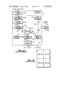
- FIG. 1 is a block diagram of the compaction/replay apparatus.
- FIG. 2 is a block diagram of the silence detector of FIG. 1.
- FIG. 3 comprised of FIGS. 3a, 3b, 3c and 3d is a detailed circuit diagram of the silence detector.
- FIG. 4a is a diagram of a representative audio input and the corresponding format for a digitally encoded signal having an audio separation of less than 700 milliseconds.
- FIG. 4b is a diagram of a representative audio input and the corresponding digitally encoded signal having an audio separation of greater than 700 milliseconds.
- FIG. 4c is a diagram of reproduced audio signals with and without feedback on the CVSD decoder in the silence detector.
- FIG. 5 is a diagram of the representative waveforms produced by the various elements of the silence detector.
- the present apparatus and in particular the silence detector is designed on the assumption that in relative terms a vocal audio signal is distinguishable from background noise.
- the vocal signal being a continuously varying signal both in magnitude and in frequency and typically having a relatively long duration (i.e. greater than approximately 100 milliseconds).
- Background noise which is resident in a vocal audio signal, on the other hand exhibiting more constant characteristics in that its magnitude and frequency remain relatively constant and that excursions of the noise signals are of a relatively short duration (i.e. less than 100 milliseconds).
- the present compaction/replay apparatus therefore takes advantage of these relative differences in signal characteristics by monitoring the magnitude and number of excursions of an incoming audio signal during a number of sampling periods to distinguish the vocal audio signal from silent periods (i.e. background noise) and deleting the silence from an encoded, compacted digital representation of the audio signal.
- FIG. 1 a block diagram of the present invention is shown and which generally discloses apparatus for digitally encoding and compacting an audio input signal, recording the encoded and compacted signal and then replaying, decoding and broadcasting the audio signal in substantially its original form. While one method of compaction (i.e. separating silence from vocal activity) has been described in the Boies et al disclosure, the present invention discloses improved apparatus for detecting the silent periods and for compacting the encoded signal in real time (i.e. with respect to the initialization of the system) as opposed to delta time (i.e. with respect to the previous sample).
- the silence detector 1 performs these functions essentially via the aid of the silence detector 1, which will be described in greater detail hereinafter, and which acts to compare the incoming audio signal to a continuously adjusted threshold which is a function of the previously received audio signal so as to distinguish periods of relative silence in the audio signal.
- a continuously adjusted threshold which is a function of the previously received audio signal so as to distinguish periods of relative silence in the audio signal.
- sync and time code markers are inserted into the encoded signal to indicate the start of an audio signal.
- no data will be stored in the speech recorder 15; and then upon the initiation of the next succeeding audio activity a new sync and time code marker will be inserted.
- the sync and time code markers are then detected and the silent periods are reinserted so that a real time representation of the audio signal is reproduced, as opposed to a delta time representation.
- the silence detector 1 Upon receipt of an incoming audio signal on conductor 3, the silence detector 1 acts to filter the silent periods from the audio signal. In particular, the silence detector 1 compares the incoming audio signal to a continuously adjusted threshold, which threshold is representative of the magnitude of previously sampled audio segments, to determine the number of times that the incoming audio signal exceeds the threshold. Depending upon the number of times within a predetermined sampling period that the level of the incoming audio signal exceeds the threshold signal, the silence detector will produce an audio detect signal. The audio detect signal is then transmitted via conductor 5 to the write control logic 7.
- the write control logic 7 in response to the audio detect signal then causes digital sync and time code markers to be produced and inserted prior to the incoming digitized audio signal.
- digital sync and time code markers are produced and inserted prior to the incoming digitized audio signal.
- the incoming audio signal on conductor 3 is encoded prior to storage in the speech recorder 15 into a continuously variable slope delta modulated (CVSD) format but may also be encoded into any other format (e.g. PCM, ADPCM, etc.).
- the write control logic 7 Upon receipt of an audio detect signal, the write control logic 7 acts to produce the various control signals necessary to synchronize the activities of the time code selector 9, the sync code selector 11, the buffer 13 and the speech recorder 15. This synchronization is performed in response to the system clock signals produced via the system clock 17 and which are transmitted to the write control logic 7 on conductor 19.
- a control signal is transmitted on conductor 21 to the time code selector 9, the sync code selector 11 and the sync code generator 23.
- This control signal causes the time code selector 9 to select its B port and the sync code detector 11 to select its D port. It is to be noted that because of this selection, the encoded data on conductor 27 will not be stored since it is blocked due to the selection of the D port and not the C port of the sync code selector 11.
- the 16 bit sync code signal is then received by the buffer 13 which is comprised of a first in first out (FIFO) memory and which acts to temporarily store the sync code, time code and digitized audio output until such time as it is full and at which time its contents will be shifted out in parallel via conductor 33 to shift register 31.
- the shift register 31 will then convert the buffer's parallel output to a serial output which can be recorded by the speech recorder 15. It is to be further recognized that the shift register 31 and buffer 13 may not be necessary for some designs, but for the present embodiment it is necessary because of the interface requirements to the storage medium of the speech recorder 15.
- the speech recorder 15 of the preferred embodiment is an MNOS BORAM, but may be replaced with any other suitable equivalent such as a CCD or MOS memory or a magnetic media.
- the specific choice for a speech recorder 15 would primarily depend on the application and the amount of digitized audio that it was desired to store.
- the control logic 7 Upon the shifting out of the sync code signal, the control logic 7 produces another control signal on conductor 21 which causes the selection of the A port of time code selector 9 and the C port of the sync code selector 11.
- the time code selector 9 is comprised of a 2 port, 1 bit multiplexer which selects between serial time code data on conductor 25 at port A and the encoded audio output of the silence detector 1 on conductor 27 at port B.
- the time code selector 9 selects the time code which is resident in the time code generator 37 which is essentially comprised of a 24 bit shift register which continously receives via conductor 39 a real time clock signal from the real time clock 41.
- each audio segment stored in speech recorder will be proceeded by a 16 bit sync code comprised of 16 ones and a 24 bit time code corresponding to the amount of time that has elapsed from initialization of the system.
- the time code generator 37 is clocked for updating (signal not shown) at a rate of once per second.
- FIGS. 4a and 4b wherein the recording format and corresponding relationship of the sync code, time code and encoded, digitized audio can be better seen. From FIGS. 4a and 4b it is also to be noted that for periods in which silence exists for less than 700 milliseconds, a digitized audio output is produced by the silence detector 1 and transmitted via conductor 27. For periods of silence greater than 700 milliseconds and during which neither a digitized audio output nor an audio detect signal are present, the new sync code and time code will be generated on the detection of the next succeeding audio segment.
- the control logic 7 Upon the transmission of the time code signal, the control logic 7 produces another control signal causing time code selector 9 to again select its B port and the encoded digitized audio output present on conductor 27.
- the digitized audio output will then be transmitted via conductors 43 and 29 and the C port of the time code selector 11 to the buffer 13 which again acts as the interface to the digitized audio output prior to transmission to the speech recorder 15.
- the speech recorder 15 will always be in a write (i.e. record) mode, unless actively switched to a read mode, and will write so long as data is present on conductor 35.
- a control signal on conductor 52 thus established the speed recorder 15 in the read mode and which inhibits further writing.
- the speech recorder 15 has the additional capability of receiving digitized sensor data containing a real time clock via conductor 47, independent of the audio storage activity.
- the sensor data essentially containing digitized data collected from various sensors which function concurrently with the audio input signal.
- An environment in which both audio signals and sensor data might typically be found would be in the cockpit of an airplane or similar command control environment.
- the read control logic 50 Upon replay of the encoded digitized audio from the speech recorder 15, the read control logic 50 produces a read control signal on conductor 52 which establishes the speech recorder 15 in a read mode. During the read mode the digitized audio will be transmitted via conductor 54 to the serial to parallel shift register 53 and then to buffer 56 which again is a FIFO memory. During replay the digitized audio is monitored via the sync detector and control logic unit 58 and the time code register 60. Upon the detection of a sync code by the sync code detector 58, which comprises a counter and associated circuitry for detecting the 16 bits of binary ones, a control signal is produced on conductor 62.
- the control signal is then transmitted to the buffer 56 and the time code register 60 and which causes the buffer 56 to prevent the loading of the sync and time codes which if allowed to remain could cause spurious audio signals.
- the buffer also acts to prevent gaps in the replayed audio which would otherwise occur due the deletion of the sync and time codes.
- the control signal on conductor 62 also causes the initiation of the time code register 60 which is comprised of a 24 bit shift register and which acts to load the time code contained in the replayed audio.
- the time code is then compared via conductor 64 in the digital comparator 66, which is comprised of a 24 bit digital comparator, to the digital clock signal on conductor 68 from the real time clock register 70.
- the real time clock signal is contained in the sensor data, as previously mentioned, and is now merely extracted from the speech recorder 15 via conductor 72 and stored in the 24 bit register which comprises the real time clock register 70.
- the extracted real time clock signal and the time code are thus compared by the comparator 66 and when an equality exists a control signal is produced on conductor 74.
- This control signal causes the read control logic 50 to produce another control signal on conductor 76 and which causes the output selector, which is comprised of a 1 bit multiplexer to select its E port and thus receive the digitized audio stored in buffer 56 via conductor 75 the parallel to serial shift register 77 and conductor 80.
- the control signal produced on conductor 76 will cause the F port of the output selector 78 to be selected. Coupled to the F port via conductor 82 is a CVSD digital output from the H port of the CVSD decoder 84 corresponding to the level of the last transmitted analog audio sample. This CVSD output will then be transmitted via conductor 86 to the CVSD decoder 84 where it will be decoded and transmitted via the G port and conductor 88 and be replayed as silence. Referring to FIG.
- a control signal will be transmitted from the read control logic 50 via conductor 52 to cause the speech recorder 15 to stop relay until a match is achieved in the comparator 66, when replay will be resumed upon detection of the match control signal on conductor 74. It is also to be noted that should buffer 56 become full a control signal will be transmitted via conductor 88 to the read control logic which will cause the speech recorder 15 to stop and permit the buffer 56 to continue transmitting its contents until such time as it can again begin to receive the digitized audio from the speech recorder 15.
- the audio signal is then low pass filtered via the 3000 hertz low pass filter 100 which is comprised of capacitors C1, C2 and C3, resistors R12, R13 and R14 and operational amplifier A3.
- the filter is thus an active filter which acts to filter high frequency background noise from the received analog audio and which improves the quality of the received signal prior to encoding. Such filtering also serves to improve the signal-to-noise ratio of the CVSD encoder 106 and to prevent frequency aliasing.
- the silence detector is clocked at a 12 kilohertz clock rate which is provided via clock 102.
- Clock 102 receives its general timing instructions from the main system clock 17 via NOR gate 103 and NAND gate 105 and causes the JK flip-flop 107 to produce complementary clock signals on its Q and Q outputs.
- the Q output being amplified via amplifier A4 and used to clock the CVSD encoder 106.
- the complementary Q clock signal being used to clock the CVSD encoded audio into the audio delay shift registers 109 and which will be described in more detail hereunder.
- the filtered audio signal is impressed on the analog input of the CVSD encoder 106, which is comprised of a Motorola Part No. MC3517 and which with its associated circuitry acts to produce a CVSD encoded audio signal.
- the CVSD encoded audio is then transmitted via conductor 108 to the audio delay element 109 which is comprised of two series coupled shift registers 111 and 113.
- the shift registers 111 and 113 then act to delay the CVSD encoded audio by a period of approximately 100 milliseconds which is the amount of time that is required to sample the analog audio signal and determine whether or not silence or audio is present.
- the delayed CVSD signal is then transmitted on conductor 27 to the time code selector 9.
- the filtered signal Upon filtering the background noise from the gain controlled audio signal, the filtered signal is impressed upon the envelope detector 133 and within which the signal is impressed on two parallel paths.
- the first path comprised of resistors R46 and R47, capacitor C16 and diode CR3 and which acts to AC couple the filtered audio signal to the comparator 129 and to halfwave rectify that signal.
- the second path comprising capacitors C15 and C17, diode CR4 and resistors R48, R49, R50 and R51 acts to integrate the filtered audio signal and produce the continuously adjusted threshold envelope voltage which is used to determine whether or not an audio signal is present.
- resistors R48 and R49 act to establish a DC offset to the audio signal prior to the halfwave rectification by diode CR4.
- the halfwave rectified signal is then integrated by the RC combination of resistors R50 and R51 and capacitor C17, and it is the charge on capacitor C17 that establishes the threshold envelope voltage. It is to be noted also that the resistors R50 and R51 are selected such that their combination will produce approximately a one millisecond charge time on capacitor C17 and a 10 millisecond discharge time, thus ensuring that each peak of the audio signal will be compared to the average level of the most recently received peaks.
- the excursion counter 139 responding to the pulsed output of comparator 129 counts the individual pulses over a 100 millisecond period.
- the 100 millisecond period is established via clock 141 which is under the control of the system clock 17.
- a record is kept of the number of times that the peak level of the analog audio signal exceeds the threshold envelope level. If within each 100 millisecond period the counter meets or exceeds a predetermined count (i.e. typically a count of 4), the counter will overflow and indicate the overflow condition by producing a pulse.
- shutoff delay element 151 is also coupled to the logic low output of OR gate 147.
- the shutoff delay element 151 responds to the logic low pulse from OR gate 147 and causes the counter 153 to count at the clock rate of clock 141 for approximately 700 milliseconds and during which time the audio detect signal will be maintained on conductor 5. If additional counter pulses are received during this 700 millisecond period, as would be indicative of continuing vocal audio activity, the counter 153 will reload itself and begin to count anew until interrupted or until the 700 milliseconds has expired and at which time inverter 155 would change states and the audio detect signal would go low, thus indicating that no audio signal was being received.
Abstract
Description
Claims (15)
Priority Applications (1)
| Application Number | Priority Date | Filing Date | Title |
|---|---|---|---|
| US06/216,031 US4376874A (en) | 1980-12-15 | 1980-12-15 | Real time speech compaction/relay with silence detection |
Applications Claiming Priority (1)
| Application Number | Priority Date | Filing Date | Title |
|---|---|---|---|
| US06/216,031 US4376874A (en) | 1980-12-15 | 1980-12-15 | Real time speech compaction/relay with silence detection |
Publications (1)
| Publication Number | Publication Date |
|---|---|
| US4376874A true US4376874A (en) | 1983-03-15 |
Family
ID=22805397
Family Applications (1)
| Application Number | Title | Priority Date | Filing Date |
|---|---|---|---|
| US06/216,031 Expired - Lifetime US4376874A (en) | 1980-12-15 | 1980-12-15 | Real time speech compaction/relay with silence detection |
Country Status (1)
| Country | Link |
|---|---|
| US (1) | US4376874A (en) |
Cited By (40)
| Publication number | Priority date | Publication date | Assignee | Title |
|---|---|---|---|---|
| EP0165604A2 (en) * | 1984-06-20 | 1985-12-27 | Casio Computer Company Limited | Recording/reproducing apparatus including a digital memory device |
| US4701937A (en) * | 1985-05-13 | 1987-10-20 | Industrial Technology Research Institute Republic Of China | Signal storage and replay system |
| EP0275099A2 (en) * | 1987-01-16 | 1988-07-20 | Sharp Kabushiki Kaisha | Voice analyzing and synthesizing apparatus |
| US4805217A (en) * | 1984-09-26 | 1989-02-14 | Mitsubishi Denki Kabushiki Kaisha | Receiving set with playback function |
| US4837827A (en) * | 1984-06-29 | 1989-06-06 | Siemens Aktiengesellschaft | Method for transmitting two independent types of information and device for implementing the method |
| EP0349664A1 (en) * | 1988-07-06 | 1990-01-10 | R. R. Donnelley & Sons Company | Digital method and system for reproducing analog data |
| US4916742A (en) * | 1986-04-24 | 1990-04-10 | Kolesnikov Viktor M | Method of recording and reading audio information signals in digital form, and apparatus for performing same |
| US4969384A (en) * | 1988-06-23 | 1990-11-13 | Yamaha Corporation | Musical score duration modification apparatus |
| US4989246A (en) * | 1989-03-22 | 1991-01-29 | Industrial Technology Research Institute, R.O.C. | Adaptive differential, pulse code modulation sound generator |
| US5054073A (en) * | 1986-12-04 | 1991-10-01 | Oki Electric Industry Co., Ltd. | Voice analysis and synthesis dependent upon a silence decision |
| FR2686183A1 (en) * | 1992-01-15 | 1993-07-16 | Idms Sa | System for digitising an audio signal, implementation method and device for compiling a digital database |
| US5293273A (en) * | 1990-08-28 | 1994-03-08 | Touchstone Applied Science Associates, Inc. | Voice actuated recording device having recovery of initial speech data after pause intervals |
| WO1995016265A1 (en) * | 1993-12-06 | 1995-06-15 | Ford Motor Company | Blank detector for cassette tape player |
| EP0658878A2 (en) * | 1993-12-13 | 1995-06-21 | Philips Patentverwaltung GmbH | System for transmitting a speech signal |
| US5491774A (en) * | 1994-04-19 | 1996-02-13 | Comp General Corporation | Handheld record and playback device with flash memory |
| US5608582A (en) * | 1993-07-27 | 1997-03-04 | Samsung Electronics Co., Ltd. | Audio signal reproducing apparatus and method for use during a slow reproduction operation |
| US5737139A (en) * | 1993-12-22 | 1998-04-07 | Goldstar Co., Ltd. | Digest variable speed reproducing apparatus for a video cassette recorder and method therefor |
| US5757565A (en) * | 1993-02-16 | 1998-05-26 | Goldstar Co., Ltd. | Digest playback apparatus and method for video cassette recorder |
| US5799279A (en) * | 1995-11-13 | 1998-08-25 | Dragon Systems, Inc. | Continuous speech recognition of text and commands |
| EP0957489A1 (en) * | 1998-05-11 | 1999-11-17 | Van de Pol, Teun | Portable device and method to record, edit and playback digital audio |
| US6049765A (en) * | 1997-12-22 | 2000-04-11 | Lucent Technologies Inc. | Silence compression for recorded voice messages |
| US6070135A (en) * | 1995-09-30 | 2000-05-30 | Samsung Electronics Co., Ltd. | Method and apparatus for discriminating non-sounds and voiceless sounds of speech signals from each other |
| WO2000038174A1 (en) * | 1998-12-22 | 2000-06-29 | Ericsson Inc. | Method and apparatus for decreasing storage requirements for a voice recording system |
| US6161087A (en) * | 1998-10-05 | 2000-12-12 | Lernout & Hauspie Speech Products N.V. | Speech-recognition-assisted selective suppression of silent and filled speech pauses during playback of an audio recording |
| EP1094446A1 (en) * | 1999-10-18 | 2001-04-25 | Lucent Technologies Inc. | Voice recording with silence compression and comfort noise generation for digital communication apparatus |
| US20030165325A1 (en) * | 2002-03-01 | 2003-09-04 | Blair Ronald Lynn | Trick mode audio playback |
| US20030165321A1 (en) * | 2002-03-01 | 2003-09-04 | Blair Ronald Lynn | Audio data deletion and silencing during trick mode replay |
| US6625387B1 (en) * | 2002-03-01 | 2003-09-23 | Thomson Licensing S.A. | Gated silence removal during video trick modes |
| US20030212548A1 (en) * | 2002-05-13 | 2003-11-13 | Petty Norman W. | Apparatus and method for improved voice activity detection |
| US20040151164A1 (en) * | 1995-10-05 | 2004-08-05 | Kubler Joseph J. | Hierarchical data collection network supporting packetized voice communications among wireless terminals and telephones |
| US20040258392A1 (en) * | 2003-04-14 | 2004-12-23 | Sony Corporation | Information processing apparatus for detecting inter-track boundaries |
| US20060120406A1 (en) * | 2004-12-03 | 2006-06-08 | Chao-Hung Wu | Internet A/V data imaging results & transmission rate improvement methodology |
| US20070248315A1 (en) * | 2005-03-01 | 2007-10-25 | Matsushita Electric Industrial Co., Ltd. | Reproducing Device and Reproducing Method |
| EP1953751A2 (en) | 2007-01-30 | 2008-08-06 | Viktor Company of Japan Ltd. | Reproduction device, reproduction method and computer usable medium having computer readable reproduction embodied therein |
| US20100040207A1 (en) * | 2005-01-14 | 2010-02-18 | At&T Intellectual Property I, L.P. | System and Method for Independently Recognizing and Selecting Actions and Objects in a Speech Recognition System |
| USRE44466E1 (en) | 1995-12-07 | 2013-08-27 | Koninklijke Philips Electronics N.V. | Method and device for packaging audio samples of a non-PCM encoded audio bitstream into a sequence of frames |
| US8751232B2 (en) | 2004-08-12 | 2014-06-10 | At&T Intellectual Property I, L.P. | System and method for targeted tuning of a speech recognition system |
| US8824659B2 (en) | 2005-01-10 | 2014-09-02 | At&T Intellectual Property I, L.P. | System and method for speech-enabled call routing |
| US9112972B2 (en) | 2004-12-06 | 2015-08-18 | Interactions Llc | System and method for processing speech |
| WO2020097220A1 (en) * | 2018-11-09 | 2020-05-14 | L3 Technologies, Inc. | Systems and methods for compressing audio data for storage and streaming from an aircraft |
Citations (6)
| Publication number | Priority date | Publication date | Assignee | Title |
|---|---|---|---|---|
| US4091242A (en) * | 1977-07-11 | 1978-05-23 | International Business Machines Corporation | High speed voice replay via digital delta modulation |
| US4093831A (en) * | 1976-10-12 | 1978-06-06 | Business Education Products, Inc. | Transcriber having selectable word reproduction rate |
| US4130739A (en) * | 1977-06-09 | 1978-12-19 | International Business Machines Corporation | Circuitry for compression of silence in dictation speech recording |
| US4277645A (en) * | 1980-01-25 | 1981-07-07 | Bell Telephone Laboratories, Incorporated | Multiple variable threshold speech detector |
| US4280192A (en) * | 1977-01-07 | 1981-07-21 | Moll Edward W | Minimum space digital storage of analog information |
| US4281218A (en) * | 1979-10-26 | 1981-07-28 | Bell Telephone Laboratories, Incorporated | Speech-nonspeech detector-classifier |
-
1980
- 1980-12-15 US US06/216,031 patent/US4376874A/en not_active Expired - Lifetime
Patent Citations (6)
| Publication number | Priority date | Publication date | Assignee | Title |
|---|---|---|---|---|
| US4093831A (en) * | 1976-10-12 | 1978-06-06 | Business Education Products, Inc. | Transcriber having selectable word reproduction rate |
| US4280192A (en) * | 1977-01-07 | 1981-07-21 | Moll Edward W | Minimum space digital storage of analog information |
| US4130739A (en) * | 1977-06-09 | 1978-12-19 | International Business Machines Corporation | Circuitry for compression of silence in dictation speech recording |
| US4091242A (en) * | 1977-07-11 | 1978-05-23 | International Business Machines Corporation | High speed voice replay via digital delta modulation |
| US4281218A (en) * | 1979-10-26 | 1981-07-28 | Bell Telephone Laboratories, Incorporated | Speech-nonspeech detector-classifier |
| US4277645A (en) * | 1980-01-25 | 1981-07-07 | Bell Telephone Laboratories, Incorporated | Multiple variable threshold speech detector |
Cited By (61)
| Publication number | Priority date | Publication date | Assignee | Title |
|---|---|---|---|---|
| EP0165604A3 (en) * | 1984-06-20 | 1986-02-05 | Casio Computer Company Limited | Recording/reproducing apparatus including a digital memory device |
| EP0165604A2 (en) * | 1984-06-20 | 1985-12-27 | Casio Computer Company Limited | Recording/reproducing apparatus including a digital memory device |
| US4837827A (en) * | 1984-06-29 | 1989-06-06 | Siemens Aktiengesellschaft | Method for transmitting two independent types of information and device for implementing the method |
| US4805217A (en) * | 1984-09-26 | 1989-02-14 | Mitsubishi Denki Kabushiki Kaisha | Receiving set with playback function |
| US4701937A (en) * | 1985-05-13 | 1987-10-20 | Industrial Technology Research Institute Republic Of China | Signal storage and replay system |
| US4916742A (en) * | 1986-04-24 | 1990-04-10 | Kolesnikov Viktor M | Method of recording and reading audio information signals in digital form, and apparatus for performing same |
| US5054073A (en) * | 1986-12-04 | 1991-10-01 | Oki Electric Industry Co., Ltd. | Voice analysis and synthesis dependent upon a silence decision |
| EP0275099A3 (en) * | 1987-01-16 | 1990-09-19 | Sharp Kabushiki Kaisha | Voice analyzing and synthesizing apparatus |
| EP0275099A2 (en) * | 1987-01-16 | 1988-07-20 | Sharp Kabushiki Kaisha | Voice analyzing and synthesizing apparatus |
| EP0537804A2 (en) * | 1987-01-16 | 1993-04-21 | Sharp Kabushiki Kaisha | Speech recording apparatus |
| EP0537804A3 (en) * | 1987-01-16 | 1993-06-09 | Sharp Kabushiki Kaisha | Speech recording apparatus |
| US4969384A (en) * | 1988-06-23 | 1990-11-13 | Yamaha Corporation | Musical score duration modification apparatus |
| EP0349664A1 (en) * | 1988-07-06 | 1990-01-10 | R. R. Donnelley & Sons Company | Digital method and system for reproducing analog data |
| US4989246A (en) * | 1989-03-22 | 1991-01-29 | Industrial Technology Research Institute, R.O.C. | Adaptive differential, pulse code modulation sound generator |
| US5293273A (en) * | 1990-08-28 | 1994-03-08 | Touchstone Applied Science Associates, Inc. | Voice actuated recording device having recovery of initial speech data after pause intervals |
| FR2686183A1 (en) * | 1992-01-15 | 1993-07-16 | Idms Sa | System for digitising an audio signal, implementation method and device for compiling a digital database |
| US5757565A (en) * | 1993-02-16 | 1998-05-26 | Goldstar Co., Ltd. | Digest playback apparatus and method for video cassette recorder |
| US5608582A (en) * | 1993-07-27 | 1997-03-04 | Samsung Electronics Co., Ltd. | Audio signal reproducing apparatus and method for use during a slow reproduction operation |
| AU677465B2 (en) * | 1993-12-06 | 1997-04-24 | Ford Motor Co. | Blank detector for cassette tape player |
| WO1995016265A1 (en) * | 1993-12-06 | 1995-06-15 | Ford Motor Company | Blank detector for cassette tape player |
| EP0658878A3 (en) * | 1993-12-13 | 1996-04-17 | Philips Patentverwaltung | System for transmitting a speech signal. |
| AU681458B2 (en) * | 1993-12-13 | 1997-08-28 | Koninklijke Philips Electronics N.V. | Method and arrangement for transmitting speech signals |
| EP0658878A2 (en) * | 1993-12-13 | 1995-06-21 | Philips Patentverwaltung GmbH | System for transmitting a speech signal |
| US5737139A (en) * | 1993-12-22 | 1998-04-07 | Goldstar Co., Ltd. | Digest variable speed reproducing apparatus for a video cassette recorder and method therefor |
| US5491774A (en) * | 1994-04-19 | 1996-02-13 | Comp General Corporation | Handheld record and playback device with flash memory |
| US6070135A (en) * | 1995-09-30 | 2000-05-30 | Samsung Electronics Co., Ltd. | Method and apparatus for discriminating non-sounds and voiceless sounds of speech signals from each other |
| US20040151164A1 (en) * | 1995-10-05 | 2004-08-05 | Kubler Joseph J. | Hierarchical data collection network supporting packetized voice communications among wireless terminals and telephones |
| US8467376B2 (en) * | 1995-10-05 | 2013-06-18 | Broadcom Corporation | Hierarchical data collection network supporting packetized voice communications among wireless terminals and telephones |
| US5799279A (en) * | 1995-11-13 | 1998-08-25 | Dragon Systems, Inc. | Continuous speech recognition of text and commands |
| US6088671A (en) * | 1995-11-13 | 2000-07-11 | Dragon Systems | Continuous speech recognition of text and commands |
| USRE44955E1 (en) | 1995-12-07 | 2014-06-17 | Koninklijke Philips N.V. | Method and device for packaging audio samples of a non-PCM encoded audio bitstream into a sequence of frames |
| USRE44466E1 (en) | 1995-12-07 | 2013-08-27 | Koninklijke Philips Electronics N.V. | Method and device for packaging audio samples of a non-PCM encoded audio bitstream into a sequence of frames |
| US6049765A (en) * | 1997-12-22 | 2000-04-11 | Lucent Technologies Inc. | Silence compression for recorded voice messages |
| EP0957489A1 (en) * | 1998-05-11 | 1999-11-17 | Van de Pol, Teun | Portable device and method to record, edit and playback digital audio |
| US6161087A (en) * | 1998-10-05 | 2000-12-12 | Lernout & Hauspie Speech Products N.V. | Speech-recognition-assisted selective suppression of silent and filled speech pauses during playback of an audio recording |
| WO2000038174A1 (en) * | 1998-12-22 | 2000-06-29 | Ericsson Inc. | Method and apparatus for decreasing storage requirements for a voice recording system |
| US6718298B1 (en) | 1999-10-18 | 2004-04-06 | Agere Systems Inc. | Digital communications apparatus |
| EP1094446A1 (en) * | 1999-10-18 | 2001-04-25 | Lucent Technologies Inc. | Voice recording with silence compression and comfort noise generation for digital communication apparatus |
| US20030165325A1 (en) * | 2002-03-01 | 2003-09-04 | Blair Ronald Lynn | Trick mode audio playback |
| US20030165321A1 (en) * | 2002-03-01 | 2003-09-04 | Blair Ronald Lynn | Audio data deletion and silencing during trick mode replay |
| US7130528B2 (en) * | 2002-03-01 | 2006-10-31 | Thomson Licensing | Audio data deletion and silencing during trick mode replay |
| US7149412B2 (en) * | 2002-03-01 | 2006-12-12 | Thomson Licensing | Trick mode audio playback |
| US6625387B1 (en) * | 2002-03-01 | 2003-09-23 | Thomson Licensing S.A. | Gated silence removal during video trick modes |
| US20030212548A1 (en) * | 2002-05-13 | 2003-11-13 | Petty Norman W. | Apparatus and method for improved voice activity detection |
| US7072828B2 (en) * | 2002-05-13 | 2006-07-04 | Avaya Technology Corp. | Apparatus and method for improved voice activity detection |
| US20040258392A1 (en) * | 2003-04-14 | 2004-12-23 | Sony Corporation | Information processing apparatus for detecting inter-track boundaries |
| US8751232B2 (en) | 2004-08-12 | 2014-06-10 | At&T Intellectual Property I, L.P. | System and method for targeted tuning of a speech recognition system |
| US9368111B2 (en) | 2004-08-12 | 2016-06-14 | Interactions Llc | System and method for targeted tuning of a speech recognition system |
| US20060120406A1 (en) * | 2004-12-03 | 2006-06-08 | Chao-Hung Wu | Internet A/V data imaging results & transmission rate improvement methodology |
| US9350862B2 (en) | 2004-12-06 | 2016-05-24 | Interactions Llc | System and method for processing speech |
| US9112972B2 (en) | 2004-12-06 | 2015-08-18 | Interactions Llc | System and method for processing speech |
| US9088652B2 (en) | 2005-01-10 | 2015-07-21 | At&T Intellectual Property I, L.P. | System and method for speech-enabled call routing |
| US8824659B2 (en) | 2005-01-10 | 2014-09-02 | At&T Intellectual Property I, L.P. | System and method for speech-enabled call routing |
| US7966176B2 (en) * | 2005-01-14 | 2011-06-21 | At&T Intellectual Property I, L.P. | System and method for independently recognizing and selecting actions and objects in a speech recognition system |
| US20100040207A1 (en) * | 2005-01-14 | 2010-02-18 | At&T Intellectual Property I, L.P. | System and Method for Independently Recognizing and Selecting Actions and Objects in a Speech Recognition System |
| US20070248315A1 (en) * | 2005-03-01 | 2007-10-25 | Matsushita Electric Industrial Co., Ltd. | Reproducing Device and Reproducing Method |
| EP1953751A2 (en) | 2007-01-30 | 2008-08-06 | Viktor Company of Japan Ltd. | Reproduction device, reproduction method and computer usable medium having computer readable reproduction embodied therein |
| US20080289479A1 (en) * | 2007-01-30 | 2008-11-27 | Victor Company Of Japan, Limited | Reproduction device, reproduction method and computer usable medium having computer readable reproduction program emodied therein |
| EP1953751A3 (en) * | 2007-01-30 | 2008-12-17 | Viktor Company of Japan Ltd. | Reproduction device, reproduction method and computer usable medium having computer readable reproduction embodied therein |
| US7714223B2 (en) | 2007-01-30 | 2010-05-11 | Victor Company Of Japan, Limited | Reproduction device, reproduction method and computer usable medium having computer readable reproduction program emodied therein |
| WO2020097220A1 (en) * | 2018-11-09 | 2020-05-14 | L3 Technologies, Inc. | Systems and methods for compressing audio data for storage and streaming from an aircraft |
Similar Documents
| Publication | Publication Date | Title |
|---|---|---|
| US4376874A (en) | Real time speech compaction/relay with silence detection | |
| US4763207A (en) | Digital method and system for reproducing analog data | |
| GB2104756A (en) | Automatic threshold tracking system | |
| EP0777211A3 (en) | A magnetic disk sampled amplitude read channel employing interpolated timing recovery for synchronous detection of embedded servo data | |
| EP1686582A3 (en) | Data readout system for optical disk | |
| KR970705139A (en) | A recording medium, a recording apparatus, a reproducing method and a reproducing apparatus (recording medium, recording apparatus, reproducing method, and reproducing apparatus) | |
| US4246615A (en) | System for recording and/or reproducing an audio signal which has been converted into a digital signal | |
| EP0769781A3 (en) | Cost reduced interpolated timing recovery in a sampled amplitude read channel | |
| EP0268481A2 (en) | Method of recording synchronized audio and video information | |
| US4125865A (en) | Recording system | |
| EP0025277A2 (en) | Record disc of video and audio information for stop-motion playback and methods and apparatus for making and playing such a record disc | |
| KR940003391A (en) | Audio image information signal reproduction device | |
| EP1217622A3 (en) | Digital data play back apparatus and method for playing back digital data | |
| US5293273A (en) | Voice actuated recording device having recovery of initial speech data after pause intervals | |
| GB2135856A (en) | Digital signal reproducing apparatus | |
| EP1103965A3 (en) | Method and apparatus for transmitting information, and reproducing apparatus, receiving apparatus and recording medium for the information, and treansmission data thereof | |
| US4183065A (en) | Video recording apparatus which samples and quantizes low frequencies and then groups and records an analog representation thereof | |
| US20050096764A1 (en) | Sound-activated recording, transmission, and playback | |
| KR0135510B1 (en) | Long time multi-channel data tape recorder with data | |
| JP2658895B2 (en) | Slice level setting device and magnetic recording device using the same | |
| US6195502B1 (en) | Stop motion video apparatus including improved dynamic range | |
| CA2148533A1 (en) | Digital signal recording apparatus with means for detecting an id signal and controlling the number of signal samples | |
| JPH087595B2 (en) | Audio signal playback device | |
| KR100296210B1 (en) | A voice signal reproducing device | |
| JPS63113982A (en) | Digital signal detecting circuit |
Legal Events
| Date | Code | Title | Description |
|---|---|---|---|
| AS | Assignment |
Owner name: SPERRY CORPORATION; 1290 AVENUE OF THE AMERICAS, N Free format text: ASSIGNMENT OF ASSIGNORS INTEREST.;ASSIGNORS:KARBAN, STEVEN H.;DREXLER, JAMES V.;HENNEN, CLEON L.;REEL/FRAME:004073/0026 Effective date: 19801210 |
|
| STCF | Information on status: patent grant |
Free format text: PATENTED CASE |
|
| MAFP | Maintenance fee payment |
Free format text: PAYMENT OF MAINTENANCE FEE, 4TH YEAR, PL 96-517 (ORIGINAL EVENT CODE: M170); ENTITY STATUS OF PATENT OWNER: LARGE ENTITY Year of fee payment: 4 |
|
| MAFP | Maintenance fee payment |
Free format text: PAYMENT OF MAINTENANCE FEE, 8TH YEAR, PL 96-517 (ORIGINAL EVENT CODE: M171); ENTITY STATUS OF PATENT OWNER: LARGE ENTITY Year of fee payment: 8 |
|
| FEPP | Fee payment procedure |
Free format text: PAYOR NUMBER ASSIGNED (ORIGINAL EVENT CODE: ASPN); ENTITY STATUS OF PATENT OWNER: LARGE ENTITY |
|
| MAFP | Maintenance fee payment |
Free format text: PAYMENT OF MAINTENANCE FEE, 12TH YEAR, LARGE ENTITY (ORIGINAL EVENT CODE: M185); ENTITY STATUS OF PATENT OWNER: LARGE ENTITY Year of fee payment: 12 |