US4374491A - Apparatus for treating and disposing of bio-hazardous waste and solid waste - Google Patents
Apparatus for treating and disposing of bio-hazardous waste and solid waste Download PDFInfo
- Publication number
- US4374491A US4374491A US06/215,836 US21583680A US4374491A US 4374491 A US4374491 A US 4374491A US 21583680 A US21583680 A US 21583680A US 4374491 A US4374491 A US 4374491A
- Authority
- US
- United States
- Prior art keywords
- chamber
- waste
- hazardous
- infectious
- ram
- Prior art date
- Legal status (The legal status is an assumption and is not a legal conclusion. Google has not performed a legal analysis and makes no representation as to the accuracy of the status listed.)
- Expired - Lifetime
Links
Images


Classifications
-
- B—PERFORMING OPERATIONS; TRANSPORTING
- B30—PRESSES
- B30B—PRESSES IN GENERAL
- B30B9/00—Presses specially adapted for particular purposes
- B30B9/30—Presses specially adapted for particular purposes for baling; Compression boxes therefor
- B30B9/3003—Details
- B30B9/3017—Odor eliminating means
-
- A—HUMAN NECESSITIES
- A61—MEDICAL OR VETERINARY SCIENCE; HYGIENE
- A61L—METHODS OR APPARATUS FOR STERILISING MATERIALS OR OBJECTS IN GENERAL; DISINFECTION, STERILISATION OR DEODORISATION OF AIR; CHEMICAL ASPECTS OF BANDAGES, DRESSINGS, ABSORBENT PADS OR SURGICAL ARTICLES; MATERIALS FOR BANDAGES, DRESSINGS, ABSORBENT PADS OR SURGICAL ARTICLES
- A61L11/00—Methods specially adapted for refuse
-
- B—PERFORMING OPERATIONS; TRANSPORTING
- B09—DISPOSAL OF SOLID WASTE; RECLAMATION OF CONTAMINATED SOIL
- B09B—DISPOSAL OF SOLID WASTE
- B09B3/00—Destroying solid waste or transforming solid waste into something useful or harmless
- B09B3/0075—Disposal of medical waste
-
- B—PERFORMING OPERATIONS; TRANSPORTING
- B30—PRESSES
- B30B—PRESSES IN GENERAL
- B30B9/00—Presses specially adapted for particular purposes
- B30B9/30—Presses specially adapted for particular purposes for baling; Compression boxes therefor
-
- B—PERFORMING OPERATIONS; TRANSPORTING
- B30—PRESSES
- B30B—PRESSES IN GENERAL
- B30B9/00—Presses specially adapted for particular purposes
- B30B9/30—Presses specially adapted for particular purposes for baling; Compression boxes therefor
- B30B9/3003—Details
- B30B9/301—Feed means
-
- B—PERFORMING OPERATIONS; TRANSPORTING
- B30—PRESSES
- B30B—PRESSES IN GENERAL
- B30B9/00—Presses specially adapted for particular purposes
- B30B9/30—Presses specially adapted for particular purposes for baling; Compression boxes therefor
- B30B9/3003—Details
- B30B9/3035—Means for conditioning the material to be pressed, e.g. paper shredding means
-
- Y—GENERAL TAGGING OF NEW TECHNOLOGICAL DEVELOPMENTS; GENERAL TAGGING OF CROSS-SECTIONAL TECHNOLOGIES SPANNING OVER SEVERAL SECTIONS OF THE IPC; TECHNICAL SUBJECTS COVERED BY FORMER USPC CROSS-REFERENCE ART COLLECTIONS [XRACs] AND DIGESTS
- Y10—TECHNICAL SUBJECTS COVERED BY FORMER USPC
- Y10S—TECHNICAL SUBJECTS COVERED BY FORMER USPC CROSS-REFERENCE ART COLLECTIONS [XRACs] AND DIGESTS
- Y10S241/00—Solid material comminution or disintegration
- Y10S241/606—Medical/surgical waste comminution
Definitions
- bio-hazardous wastes are not very combustible, due to their high water content and their high content of quasi-combustible materials such as plastics, artificial fibers, and the like.
- complete incineration of bio-hazardous materials requires a substantial fuel input to achieve temperatures sufficient to render total the combustion of the wastes.
- the steep increases in fuel costs in recent years have greatly increased the operating cost of an incinerator. These costs are likely to increase significantly in the near future.
- an incinerator equipped with a stack gas scrubber is a sophisticated mechanism which requires a licensed operator or engineer to be in attendance on a continuing basis.
- modern incinerators involve not only high capital outlays initially, but also high fuel costs and high labor costs as well.
- incinerators produce ash and soot which create their own handling and disposal problems.
- the present invention generally comprises an apparatus which is designed to neutralize and dispose of bio-hazardous wastes and non-hazardous solid wastes, especially those generated by medical institutions and treatment facilities. Compared to prior art techniques, the apparatus of the present invention requires far less energy input, emits no air pollutants whatsoever, provides a safe temporary storage area for bio-hazardous wastes, and substantially reduces the total volume of disposed wastes.
- the apparatus comprises a generally rectangular housing having an upper chamber adapted to receive and store bio-hazardous and infectious solid wastes, and a lower chamber adapted to receive and store non-hazardous solid wastes.
- the upper chamber includes an intake door opening externally of the housing, as well as a discharge door which opens internally in the housing.
- the side of the chamber opposite the discharge door comprises a movable wall which is translatable by an hydraulic piston.
- the walls and doors of the upper chamber are provided with pressure seals so that the chamber may retain steam under pressure.
- the steam which may be provided externally by an existing steam line commonly available at medical institutions, is introduced into the upper chamber for a period of time to sterilize the contents thereof. Subsequently, the discharge door is opened and the opposing wall is translated to discharge the contents of the upper chamber into the lower chamber.
- the lower chamber also includes an intake door which opens exteriorly of the housing.
- One wall of the lower chamber is provided with a port which is in open communication with a closed compactor container.
- the wall of the lower chamber opposite the port comprises a compactor ram which is translatable by a second hydraulic cylinder.
- Solid wastes of the non-hazardous variety may be stored in the lower chamber, to which is added the neutralized solid wastes which are discharged from the upper chamber.
- the compactor ram may be actuated to compress the accumulated wastes in the chamber and push them through the port into the compactor container.
- the compaction process reduces the volume of solid waste by a factor of seven or more.
- the compactor container When the compactor container is filled, it may be transported to a land-fill site and emptied.
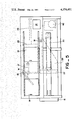
- FIG. 1 is a perspective view of the waste disposal apparatus of the present invention.
- FIG. 2 is a side elevation of the apparatus of the present invention.
- FIG. 3 is a cross-sectional elevation of the apparatus as shown in FIG. 2.
- FIG. 4 is a cross-sectional view of the apparatus as shown in FIG. 2.
- FIG. 5 is a side elevation of the apparatus of the present invention.
- FIG. 6, FIG. 7, and FIG. 8 are cross-sectional side elevations of the apparatus of the invention, showing the sequential operation thereof.
- the present invention generally comprises an apparatus for treating and neutralizing infectious bio-hazardous solid wastes, and disposing of these neutralized wastes along with other non-hazardous solid wastes.
- the apparatus includes a large rectangular housing 11 having on one side a control panel door 12 adjacent to one end of the housing. Disposed on the same side of the housing is a door 13 disposed medially in the side and a door 14 disposed adjacent to the other end of the housing. As shown in FIG. 1, the other end of the housing includes a discharge port 16.
- a chamber 17 which is adapted to receive infectious and other bio-hazardous solid wastes.
- the chamber 17 is disposed in the upper medial portion of the housing 11, and access to the chamber 17 is through the door 13.
- the chamber 17 is generally rectangular, having fixed, opposed side walls and top and bottom walls.
- the end wall 18 of the chamber 17 is supported by hinges 19 at the upper edge thereof to form an internally opening discharge door for the chamber 17.
- the door is rotated from the closed position (FIG. 6) to the open position (FIG. 7) by means of an hydraulic cylinder 21.
- the cylinder 21 is secured to the frame of the housing 11 adjacent to the side opposite the door 13 of the chamber 17.
- the translatable piston of the cylinder 21 is pivotally secured to the hinged panel 18 to effect rotation thereof, as shown also in FIG. 5.
- the end wall of the chamber 17 opposite the end wall 18 comprises a translatable ram 22 which is selectively translatable by means of an hydraulic cylinder 23, as shown in FIGS. 5-8.
- the ram 22, the hinged wall 18, and the external door 13 are all provided with pressure sealing fittings so that the chamber 17 may retain elevated gas pressure.
- an external source of pressurized steam is connected through appropriate controls and valves in the housing 11 to the chamber 17. With the ram 22 retracted, as shown in FIG. 6, and with the doors 13 and 18 closed, pressurized steam may be introduced into the chamber 17 to heat and sterilize the contents of the chamber.
- the steam heating procedure is controlled by automatic devices known in the prior art and capable of monitoring the temperature and timing of the steam heating cycle.
- an antechamber 24 which provides clearance for the panel 18 to rotate upwardly therein.
- a compaction chamber 26 Directly below the antechamber 24 is a compaction chamber 26.
- the non-hazardous solid wastes which are received in the apparatus through the door 14 enter the antechamber 24 and fall directly into the compaction chamber 26.
- the sterilized wastes from the chamber 17 which are ejected by the ram 22 into the antechamber 24 also fall into the compaction chamber 26.
- the compaction chamber 26 includes side walls and a bottom wall which are disposed in rectangular relationship.
- One end wall of the chamber 26 is provided with a discharge port 16.
- the wall opposite the port 16 is formed by a compactor ram 27.
- the rear face of the compactor ram 27 includes laterally extending reinforcing members 28 as shown in FIG. 3.
- a pair of trapezoidal panels 29 extend rearwardly from the side edges of the ram 27.
- Joined to the upper edges of the panels 29 are a plurality of rollers 31.
- the rollers are supported on longitudinally extending, L-shaped track members 32, as shown in FIG. 3. The ram is thus supported by the rollers 31 on the track 32 to facilitate reciprocal translation of the ram.
- the ram 27 is translated by means of an hydraulic cylinder 33 extending longitudinally in the housing 11 beneath the chamber 17 and the hydraulic cylinder 23.
- the piston rod 34 of the hydraulic cylinder 33 is secured to a medial portion of the ram 27, as shown in FIG. 3.
- the apparatus of the present invention is designed to operate cooperatively in association with a closed compactor container 41, as shown in FIG. 2.
- the compactor container 41 which is known in the prior art, is a reinforced, closed, rectangular container having a single opening in one end thereof, to which the discharge port 16 is designed to mate.
- the discharge port 16 is designed to mate.
- the housing 11 also includes therein an hydraulic pump 42 which supplies the hydraulic cylinders 23 and 33. Automatic controls known in the prior art are also provided for the pump 42.
- all infectious and bio-hazardous wastes are placed in the chamber 17 by means of the exterior door 13.
- the hinged wall 18 is closed and the ram 22 is retracted, as shown in FIG. 6.
- the chamber 17 has a substantial volume, on the order of 3.5 cubic yards, so that a great amount of bio-hazardous wastes may be placed in the chamber 17.
- the bio-hazardous wastes may be placed in the chamber 17 as they are created, so that the chamber 17 also serves as an isolated storage area for the bio-hazardous solid wastes.
- the chamber 26 may be used to store non-hazardous solid wastes as they are created, the solid wastes being introduced therein through the exterior door 14.
- the apparatus of the present invention serves an important waste storage function, as well as treatment and disposal of the wastes.
- the hinged wall 18 is pivoted to the open position by the hydraulic cylinder 21.
- the ram 22 is then extended, as shown in FIG. 7, thereby pushing all of the sterilized waste from the chamber 17 into the antechamber 24.
- the sterilized waste falls into the compactor chamber 26, where it mingles with the non-hazardous solid waste placed there previously.
- the ram 27 is advanced by the hydraulic cylinder 33.
- the waste accumulated in the chamber 26 is thus driven through the discharge port 16 into the compactor container 41, as shown in FIG. 8.
- the hydraulic cylinders 21, 23, and 33 may then be retracted to return the apparatus to its loading configuration.
- the preferred embodiment of the present invention is used in conjunction with a closed compactor container 41, known in the prior art and having a capacity of approximately 18 cubic yards. When this container is full, it holds the equivalent of approximately 120-130 cubic yards of non-compacted waste.
- the full container may be removed from the site of the apparatus 11, transported to a land-fill site or the like, emptied, and returned to the apparatus.
- the apparatus of the present invention discharges absolutely no pollutants into the atmosphere or environment. Furthermore, operation of the present invention is fully automatic, and may be accomplished by maintenance or housekeeping personnel. The cost of operating the apparatus is approximately 28 cents per hour, compared to incinerator operating costs of approximately $5.00 to $10.00 per hour. Thus the present invention represents a substantial improvement over prior art hazardous and non-hazardous waste disposal methods.
Abstract
Description
Claims (4)
Priority Applications (1)
| Application Number | Priority Date | Filing Date | Title |
|---|---|---|---|
| US06/215,836 US4374491A (en) | 1980-12-12 | 1980-12-12 | Apparatus for treating and disposing of bio-hazardous waste and solid waste |
Applications Claiming Priority (1)
| Application Number | Priority Date | Filing Date | Title |
|---|---|---|---|
| US06/215,836 US4374491A (en) | 1980-12-12 | 1980-12-12 | Apparatus for treating and disposing of bio-hazardous waste and solid waste |
Publications (1)
| Publication Number | Publication Date |
|---|---|
| US4374491A true US4374491A (en) | 1983-02-22 |
Family
ID=22804601
Family Applications (1)
| Application Number | Title | Priority Date | Filing Date |
|---|---|---|---|
| US06/215,836 Expired - Lifetime US4374491A (en) | 1980-12-12 | 1980-12-12 | Apparatus for treating and disposing of bio-hazardous waste and solid waste |
Country Status (1)
| Country | Link |
|---|---|
| US (1) | US4374491A (en) |
Cited By (32)
| Publication number | Priority date | Publication date | Assignee | Title |
|---|---|---|---|---|
| US4552720A (en) * | 1983-01-24 | 1985-11-12 | American Sterilizer Company | Debris compressing autoclave |
| US4860958A (en) * | 1988-05-27 | 1989-08-29 | Yerman Emil A | Plastic syringe destruction device |
| US5084250A (en) * | 1990-01-29 | 1992-01-28 | Bromac Enterprises, A Partnership | Apparatus for treating and disposing of bio-hazardous waste and solid waste |
| WO1992004058A1 (en) * | 1990-09-05 | 1992-03-19 | Abb Sanitec, Inc. | Filling sluice for treating infectious waste |
| US5124125A (en) * | 1990-07-10 | 1992-06-23 | Brent David A | Method for processing infectious waste using microwaves |
| US5124126A (en) * | 1989-01-24 | 1992-06-23 | Ripp Gerard A | Medical/dental office waste disposal |
| US5130092A (en) * | 1990-08-08 | 1992-07-14 | Hsin Liu | Biological waste sterilization and fuel product therefrom |
| WO1992012738A1 (en) * | 1991-01-25 | 1992-08-06 | Lersner Wolf A | Process and device for the disposal of medical waste |
| US5181463A (en) * | 1991-09-12 | 1993-01-26 | M. Glosser & Sons, Inc. | Integrated precompacting trash compactor |
| US5193455A (en) * | 1991-09-12 | 1993-03-16 | M. Glosser & Sons, Inc. | Trash compactor |
| US5252290A (en) * | 1989-11-30 | 1993-10-12 | Jun Uesugi | Process for treatment and disposal of medical waste materials |
| US5364589A (en) * | 1991-04-01 | 1994-11-15 | Sterile Systems, Inc. | Method and apparatus for sterilizing biological waste |
| US5389346A (en) * | 1992-03-18 | 1995-02-14 | Copeland, Jr.; Maxie L. | Bio-hazardous waste compactor |
| US5389347A (en) * | 1993-10-01 | 1995-02-14 | Bromac Enterprises | Bio-hazardous waste sterilizer and compactor |
| US5470546A (en) * | 1994-06-24 | 1995-11-28 | Hall; John L. | Apparatus for storing and sterilizing bio-hazardous waste |
| US5476634A (en) * | 1990-03-30 | 1995-12-19 | Iit Research Institute | Method and apparatus for rendering medical materials safe |
| US5508004A (en) * | 1989-10-13 | 1996-04-16 | Stericycle, Inc. | Apparatus and method for processing medical waste |
| US5529687A (en) * | 1990-09-05 | 1996-06-25 | Sanitec, Inc. | Filling sluice for appliances for the treatment of infectious waste |
| US5614157A (en) * | 1993-10-01 | 1997-03-25 | Darlene Hall | Unitized infectious waste processor and waste processing method |
| US5641423A (en) * | 1995-03-23 | 1997-06-24 | Stericycle, Inc. | Radio frequency heating apparatus for rendering medical materials |
| US5666878A (en) * | 1994-08-26 | 1997-09-16 | Dover Corporation | Waste disposal system which includes a vessel with an outer cooling jacket |
| US5709842A (en) * | 1989-10-13 | 1998-01-20 | Stericycle, Inc. | Apparatus and method for processing medical waste |
| US5746988A (en) * | 1995-11-24 | 1998-05-05 | Darlene Hall | Apparatus for processing bio-harzardous waste |
| US5816145A (en) * | 1997-05-08 | 1998-10-06 | Daniel Glosser, Tdba Glosser Manufacturing Co. | Trash compactor |
| US6139793A (en) * | 1997-09-05 | 2000-10-31 | Hydroclave Systems Corporation | Waste treatment control system |
| US6248985B1 (en) | 1998-06-01 | 2001-06-19 | Stericycle, Inc. | Apparatus and method for the disinfection of medical waste in a continuous manner |
| US6298576B1 (en) * | 1998-03-25 | 2001-10-09 | Antonio La Gioia | Cage compactor dryer apparatus for treating waste materials |
| US6412406B1 (en) * | 1999-09-23 | 2002-07-02 | Advanced Custom Engineered Systems & Equipment Inc. | Trash compactor |
| ES2192957A1 (en) * | 2001-10-05 | 2003-10-16 | Imabe Iberica S A | Automatic closing system of the grooves for the passing of needles in the pressing and bundling carts for the urban wastes bales or others. |
| US20040238397A1 (en) * | 2003-06-02 | 2004-12-02 | Chin-Liang Lin | Biological hazard protection store and collective bag |
| US20130319264A1 (en) * | 2012-06-01 | 2013-12-05 | Wastequip, Llc | Waste compactor |
| US11352206B2 (en) * | 2012-09-04 | 2022-06-07 | Maricap Oy | Apparatus for processing material, and waste container/separating device |
Citations (9)
| Publication number | Priority date | Publication date | Assignee | Title |
|---|---|---|---|---|
| US3547577A (en) * | 1968-11-12 | 1970-12-15 | American Sterilizer Co | Refuse sterilization system |
| US3691648A (en) * | 1970-02-09 | 1972-09-19 | Keller & Knappich Gmbh | Apparatus for dampening garbage in a garbage loading truck |
| GB1346262A (en) * | 1971-03-03 | 1974-02-06 | Kloeckner Humboldt Deutz Ag | Milling and drying plant |
| US3831514A (en) * | 1972-01-07 | 1974-08-27 | K Jernstrom | Deodorized garbage compactor and appurtenances |
| US3926107A (en) * | 1973-08-07 | 1975-12-16 | Peter Dunlap | Apparatus for applying deodorizing chemicals to compacted refuse |
| US3948167A (en) * | 1972-10-17 | 1976-04-06 | Aktiebolaget Svenska Flaktfabriken | Arrangement at central suction installations for suction conveyance of refuse and waste |
| DE2505185A1 (en) * | 1975-02-07 | 1976-08-19 | Otto Prof Dr Anna | Infected garbage removal from hospitals - includes treating with steam, infrared radiation and fluid bed heating |
| GB2004020A (en) * | 1977-09-09 | 1979-03-21 | Better Built Mach Corp | Door and seal construction for sterilizers |
| JPS54109261A (en) * | 1978-02-15 | 1979-08-27 | Shin Meiwa Ind Co Ltd | Apparatus for detecting bridges of wastes in waste forcing equipment |
-
1980
- 1980-12-12 US US06/215,836 patent/US4374491A/en not_active Expired - Lifetime
Patent Citations (9)
| Publication number | Priority date | Publication date | Assignee | Title |
|---|---|---|---|---|
| US3547577A (en) * | 1968-11-12 | 1970-12-15 | American Sterilizer Co | Refuse sterilization system |
| US3691648A (en) * | 1970-02-09 | 1972-09-19 | Keller & Knappich Gmbh | Apparatus for dampening garbage in a garbage loading truck |
| GB1346262A (en) * | 1971-03-03 | 1974-02-06 | Kloeckner Humboldt Deutz Ag | Milling and drying plant |
| US3831514A (en) * | 1972-01-07 | 1974-08-27 | K Jernstrom | Deodorized garbage compactor and appurtenances |
| US3948167A (en) * | 1972-10-17 | 1976-04-06 | Aktiebolaget Svenska Flaktfabriken | Arrangement at central suction installations for suction conveyance of refuse and waste |
| US3926107A (en) * | 1973-08-07 | 1975-12-16 | Peter Dunlap | Apparatus for applying deodorizing chemicals to compacted refuse |
| DE2505185A1 (en) * | 1975-02-07 | 1976-08-19 | Otto Prof Dr Anna | Infected garbage removal from hospitals - includes treating with steam, infrared radiation and fluid bed heating |
| GB2004020A (en) * | 1977-09-09 | 1979-03-21 | Better Built Mach Corp | Door and seal construction for sterilizers |
| JPS54109261A (en) * | 1978-02-15 | 1979-08-27 | Shin Meiwa Ind Co Ltd | Apparatus for detecting bridges of wastes in waste forcing equipment |
Cited By (39)
| Publication number | Priority date | Publication date | Assignee | Title |
|---|---|---|---|---|
| US4552720A (en) * | 1983-01-24 | 1985-11-12 | American Sterilizer Company | Debris compressing autoclave |
| US4860958A (en) * | 1988-05-27 | 1989-08-29 | Yerman Emil A | Plastic syringe destruction device |
| US5124126A (en) * | 1989-01-24 | 1992-06-23 | Ripp Gerard A | Medical/dental office waste disposal |
| US5833922A (en) * | 1989-10-13 | 1998-11-10 | Stericycle, Inc. | Apparatus and method for processing medical waste |
| US5830419A (en) * | 1989-10-13 | 1998-11-03 | Stericycle, Inc. | Apparatus and method for processing medical waste |
| US5709842A (en) * | 1989-10-13 | 1998-01-20 | Stericycle, Inc. | Apparatus and method for processing medical waste |
| US5508004A (en) * | 1989-10-13 | 1996-04-16 | Stericycle, Inc. | Apparatus and method for processing medical waste |
| US5252290A (en) * | 1989-11-30 | 1993-10-12 | Jun Uesugi | Process for treatment and disposal of medical waste materials |
| US5084250A (en) * | 1990-01-29 | 1992-01-28 | Bromac Enterprises, A Partnership | Apparatus for treating and disposing of bio-hazardous waste and solid waste |
| US5476634A (en) * | 1990-03-30 | 1995-12-19 | Iit Research Institute | Method and apparatus for rendering medical materials safe |
| US5124125A (en) * | 1990-07-10 | 1992-06-23 | Brent David A | Method for processing infectious waste using microwaves |
| US5130092A (en) * | 1990-08-08 | 1992-07-14 | Hsin Liu | Biological waste sterilization and fuel product therefrom |
| JPH07102223B2 (en) * | 1990-09-05 | 1995-11-08 | エービービー サニテック インコーポレイテッド | Filling weir for feeding infectious waste |
| US5529687A (en) * | 1990-09-05 | 1996-06-25 | Sanitec, Inc. | Filling sluice for appliances for the treatment of infectious waste |
| WO1992004058A1 (en) * | 1990-09-05 | 1992-03-19 | Abb Sanitec, Inc. | Filling sluice for treating infectious waste |
| WO1992012738A1 (en) * | 1991-01-25 | 1992-08-06 | Lersner Wolf A | Process and device for the disposal of medical waste |
| US5217688A (en) * | 1991-01-25 | 1993-06-08 | Lersner Wolf A | Process for the disposal of medical waste |
| US5364589A (en) * | 1991-04-01 | 1994-11-15 | Sterile Systems, Inc. | Method and apparatus for sterilizing biological waste |
| US5193455A (en) * | 1991-09-12 | 1993-03-16 | M. Glosser & Sons, Inc. | Trash compactor |
| US5181463A (en) * | 1991-09-12 | 1993-01-26 | M. Glosser & Sons, Inc. | Integrated precompacting trash compactor |
| US5389346A (en) * | 1992-03-18 | 1995-02-14 | Copeland, Jr.; Maxie L. | Bio-hazardous waste compactor |
| US5389347A (en) * | 1993-10-01 | 1995-02-14 | Bromac Enterprises | Bio-hazardous waste sterilizer and compactor |
| US5614157A (en) * | 1993-10-01 | 1997-03-25 | Darlene Hall | Unitized infectious waste processor and waste processing method |
| US5470546A (en) * | 1994-06-24 | 1995-11-28 | Hall; John L. | Apparatus for storing and sterilizing bio-hazardous waste |
| US5666878A (en) * | 1994-08-26 | 1997-09-16 | Dover Corporation | Waste disposal system which includes a vessel with an outer cooling jacket |
| US5641423A (en) * | 1995-03-23 | 1997-06-24 | Stericycle, Inc. | Radio frequency heating apparatus for rendering medical materials |
| US5746988A (en) * | 1995-11-24 | 1998-05-05 | Darlene Hall | Apparatus for processing bio-harzardous waste |
| US5816145A (en) * | 1997-05-08 | 1998-10-06 | Daniel Glosser, Tdba Glosser Manufacturing Co. | Trash compactor |
| US6139793A (en) * | 1997-09-05 | 2000-10-31 | Hydroclave Systems Corporation | Waste treatment control system |
| US6752956B1 (en) | 1997-09-05 | 2004-06-22 | Hydroclave Systems Corporation | Waste treatment control system |
| US6298576B1 (en) * | 1998-03-25 | 2001-10-09 | Antonio La Gioia | Cage compactor dryer apparatus for treating waste materials |
| US6248985B1 (en) | 1998-06-01 | 2001-06-19 | Stericycle, Inc. | Apparatus and method for the disinfection of medical waste in a continuous manner |
| US6344638B1 (en) | 1998-06-01 | 2002-02-05 | Stericycle, Inc. | Method for the disinfection of medical waste in a continuous manner |
| US6412406B1 (en) * | 1999-09-23 | 2002-07-02 | Advanced Custom Engineered Systems & Equipment Inc. | Trash compactor |
| ES2192957A1 (en) * | 2001-10-05 | 2003-10-16 | Imabe Iberica S A | Automatic closing system of the grooves for the passing of needles in the pressing and bundling carts for the urban wastes bales or others. |
| US20040238397A1 (en) * | 2003-06-02 | 2004-12-02 | Chin-Liang Lin | Biological hazard protection store and collective bag |
| US20130319264A1 (en) * | 2012-06-01 | 2013-12-05 | Wastequip, Llc | Waste compactor |
| US9751118B2 (en) * | 2012-06-01 | 2017-09-05 | Wastequip, Llc | Waste compactor |
| US11352206B2 (en) * | 2012-09-04 | 2022-06-07 | Maricap Oy | Apparatus for processing material, and waste container/separating device |
Similar Documents
| Publication | Publication Date | Title |
|---|---|---|
| US4374491A (en) | Apparatus for treating and disposing of bio-hazardous waste and solid waste | |
| US5389347A (en) | Bio-hazardous waste sterilizer and compactor | |
| US4402791A (en) | Apparatus for pyrolyzing shredded tires | |
| US20080048059A1 (en) | System and Method for Processing Waste on a Continuous Basis | |
| US6732962B1 (en) | Waste treatment apparatus | |
| EP0277507A2 (en) | Disinfection device for contaminated household refuse | |
| CA1262655A (en) | Refuse treatment apparatus | |
| US5437237A (en) | Continuous pyrolysis system | |
| US5470546A (en) | Apparatus for storing and sterilizing bio-hazardous waste | |
| EP0430898B1 (en) | Refuse-treating unit | |
| KR100678563B1 (en) | A method and apparatus for incineration of waste barreled in drum | |
| US4974527A (en) | Mobile incinerator system for low level radioactive solid waste | |
| CN108980848A (en) | A kind of house refuse pretreatment unit | |
| CZ21515U1 (en) | Apparatus for heat treatment of organic materials, especially waste materials | |
| KR20210025829A (en) | Combustible Radioactive Waste Injection Module and Mobile Radioactive Waste Disposal Apparatus Including It | |
| CN213453669U (en) | Heat treatment device for treating garbage | |
| CN1136169C (en) | Refuse processing method and apparatus | |
| CN217172488U (en) | Sealed collection chamber of upper box mechanism | |
| KR100336802B1 (en) | Batch charging type incinerator | |
| CN212502172U (en) | Biohazard garbage treatment device | |
| CN219375586U (en) | Microwave garbage sterilizing equipment | |
| CN220722267U (en) | Dangerous waste garbage collecting box capable of automatically closing sealing door | |
| RU2111567C1 (en) | Device for filling bags with solid radioactive wastes, their compression, and packing | |
| KR200383787Y1 (en) | Drum loader | |
| ITME960016A1 (en) | WASTE COLLECTORS AND COMPACTORS |
Legal Events
| Date | Code | Title | Description |
|---|---|---|---|
| AS | Assignment |
Owner name: CLE, SANTA BARBARA, CA. 93105; DON J. STORTROEN, 1 Free format text: ASSIGNMENT OF ASSIGNORS INTEREST.;ASSIGNORS:STORTROEN, DON J.;BROWN, MICHAEL L.;REEL/FRAME:004052/0598 Effective date: 19820930 |
|
| STCF | Information on status: patent grant |
Free format text: PATENTED CASE |
|
| MAFP | Maintenance fee payment |
Free format text: PAYMENT OF MAINTENANCE FEE, 4TH YEAR, PL 96-517 (ORIGINAL EVENT CODE: M170); ENTITY STATUS OF PATENT OWNER: LARGE ENTITY Year of fee payment: 4 |
|
| FEPP | Fee payment procedure |
Free format text: MAINTENANCE FEE HAS ALREADY BEEN PAID. REFUND IS SCHEDULED (ORIGINAL EVENT CODE: F160); ENTITY STATUS OF PATENT OWNER: LARGE ENTITY |
|
| MAFP | Maintenance fee payment |
Free format text: PAYMENT OF MAINTENANCE FEE, 8TH YEAR, PL 96-517 (ORIGINAL EVENT CODE: M171); ENTITY STATUS OF PATENT OWNER: LARGE ENTITY Year of fee payment: 8 |
|
| FEPP | Fee payment procedure |
Free format text: PAYOR NUMBER ASSIGNED (ORIGINAL EVENT CODE: ASPN); ENTITY STATUS OF PATENT OWNER: LARGE ENTITY |
|
| AS | Assignment |
Owner name: HALL, VERN W., ALASKA Free format text: ASSIGNMENT AND JOINT OWNERSHIP AGREEMENT;ASSIGNOR:BROMAC ENTERPRISES;REEL/FRAME:007244/0203 Effective date: 19941006 Owner name: HALL, DARLENE, WASHINGTON Free format text: ASSIGNMENT AND JOINT OWNERSHIP AGREEMENT;ASSIGNOR:BROMAC ENTERPRISES;REEL/FRAME:007244/0203 Effective date: 19941006 Owner name: HALL, JOHN L., CALIFORNIA Free format text: ASSIGNMENT AND JOINT OWNERSHIP AGREEMENT;ASSIGNOR:BROMAC ENTERPRISES;REEL/FRAME:007244/0203 Effective date: 19941006 Owner name: HALL, WILBURN E., OREGON Free format text: ASSIGNMENT AND JOINT OWNERSHIP AGREEMENT;ASSIGNOR:BROMAC ENTERPRISES;REEL/FRAME:007244/0203 Effective date: 19941006 |