US4338632A - Remote control system for television monitors - Google Patents
Remote control system for television monitors Download PDFInfo
- Publication number
- US4338632A US4338632A US06/194,163 US19416380A US4338632A US 4338632 A US4338632 A US 4338632A US 19416380 A US19416380 A US 19416380A US 4338632 A US4338632 A US 4338632A
- Authority
- US
- United States
- Prior art keywords
- pulses
- control
- counter
- output
- signal
- Prior art date
- Legal status (The legal status is an assumption and is not a legal conclusion. Google has not performed a legal analysis and makes no representation as to the accuracy of the status listed.)
- Expired - Lifetime
Links
Images


Classifications
-
- H—ELECTRICITY
- H04—ELECTRIC COMMUNICATION TECHNIQUE
- H04N—PICTORIAL COMMUNICATION, e.g. TELEVISION
- H04N5/00—Details of television systems
- H04N5/44—Receiver circuitry for the reception of television signals according to analogue transmission standards
-
- H—ELECTRICITY
- H04—ELECTRIC COMMUNICATION TECHNIQUE
- H04B—TRANSMISSION
- H04B1/00—Details of transmission systems, not covered by a single one of groups H04B3/00 - H04B13/00; Details of transmission systems not characterised by the medium used for transmission
- H04B1/06—Receivers
- H04B1/16—Circuits
- H04B1/20—Circuits for coupling gramophone pick-up, recorder output, or microphone to receiver
- H04B1/202—Circuits for coupling gramophone pick-up, recorder output, or microphone to receiver by remote control
Definitions
- This invention is directed generally to television displays, and particularly to a system for remotely controlling the operation of a television monitor.
- Modern technology has produced a number of products such as video disk players, video cassette players and the like which develop video signals. All such signals may be used to generate corresponding video images on one or more television monitors which may be located at a spot remote from the source of video signals.
- the monitor's source of video signals from a video disk player to a cassette player, for example, or to any other source of video signals.
- the video signals from the second video source may vary from those provided by the first video source such that a change in hue is experienced in the image which is reproduced by the monitor. Brightness, contrast, and other changes may also result when the video input to the monitor changes.
- each monitor includes user-operated controls for adjusting the hue, brightness and other variables associated with the reproduced images.
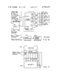
- FIG. 1 is a schematic representation of an encoding and decoding system for remotely adjusting the control functions of one or more television monitors;
- FIG. 2 illustrates a multi-channel control signal developed by the encoder of FIG. 1 according to the invention
- FIG. 3 is an expanded view of the interval A-B of FIG. 2;
- FIG. 4 depicts one embodiment of the encoder shown in FIG. 1;
- FIG. 5 depicts various waveforms useful in explaining the operation of the encoder shown in FIG. 4;
- FIG. 6 is a detailed circuit diagram illustrating how the encoder of FIG. 4 may be constructed
- FIG. 7 is a diagram of one embodiment of the decoder shown in FIG. 1;
- FIG. 8 depicts various waveforms useful in explaining the operation of the decoder shown in FIG. 7;
- FIG. 9 illustrates the details of low pass filters and the amplifiers depicted in FIG. 7;
- FIG. 10 illustrates a system for transmitting the encoder's multi-channel signal and the video from the video sources of FIG. 1 to the decoders and monitors on a super video carrier;
- FIG. 11 shows a system for transmitting the encoder's multi-channel signal to a decoder via a twisted pair of wires
- FIG. 12 is a simplified block diagram of another system according to the invention for remotely adjusting a monitor's control functions by a multichannel control signal inserted into the vertical interval of the video which is supplied to the monitor;
- FIG. 13 illustrates the way in which a video signal is caused to carry the multi-channel control signal in its vertical interval
- FIG. 14 depicts the encoder of FIG. 12 in more detail
- FIG. 15 is a detailed circuit diagram of the encoder shown in FIG. 14;
- FIG. 16 is a block diagram of the decoder shown in FIG. 12;
- FIG. 17 shows how the decoder of FIG. 16 may be interfaced with its associated monitor
- FIG. 18 is a more detailed circuit diagram of portions of the decoder shown in FIG. 16.
- the video signal sources may include a television receiver 10, a video disk player 12, a video cassette player 14, and a camera 16.
- a pair of television monitors 18 and 20 are shown, both of which can simultaneously convert the video signals from one of the sources 10-16 to images.
- a switch 22 is included. As shown, the switch 22 includes input contacts 24, 26, 28, and 30, each of which receives video signals from one of the sources 10-16. Also included is a switch arm 32 which is coupled to the inputs of monitors 18 and 20 via a cable 34. Placing the switch arm 32 in contact with one of the contacts 24-30 couples one of the signal sources to the monitors.
- the monitors may include a number of control functions such as hue, contrast, volume and the like. Conventionally, all such functions may be adjusted by user-operable knobs (not shown) on the monitors. However, with the knobs set for proper operation when the arm 32 couples the player 12 to the monitors, the knobs may need adjustment when the arm 32 is switched to the cassette player 14.
- an encoder 36 is included.
- the encoder generates a multichannel control signal (one channel for each of the monitor's control functions) which is coupled to a pair of decoders 18a and 20a via a transmission path 38.
- the multi-channel signal developed by the encoder 36 is a time-division multiplexed signal wherein each channel of the signal includes a control pulse having a parameter which is variable by user-operable controls (not shown) associated with the encoder 36.
- the decoders 18a and 20a convert the control pulses to a corresponding number of D.C. signals for use in automatically adjusting the control functions, such as hue or brightness, which are associated with the monitors. With this arrangement, one encoder may simultaneously control a plurality of remotely located monitors.
- one type of multichannel signal 40 is shown which may be developed by the encoder 36.
- the illustrated signal has a constant period which extends from A to C and which repeats continuously. Included within the period A-C is a start pulse 42, six consecutive control pulses 44-54, and a dead time extending from B to C. Each of the control pulses 44-54 is associated with one of six channels, and each channel is intended to control one of the functions of the monitors.
- control pulse 44 is associated with channel No. 1
- control pulse 46 is associated with channel No. 2, and so on.
- each of the six control pulses has a pulse period which is variable.
- the pulse period of control pulse 44 extends from C to D
- the pulse period of control pulse 46 extends from D to E.
- the duration of the pulse period C-D the information content of channel No. 1 is varied.
- varying the duration of the pulse period D-E varies the information content of channel 2.
- the information content of the other channels is varied in the same manner.
- the pulse periods of the various channels will also vary the interval from A to B, and thereby vary the length of the dead time interval B-C (FIG. 2).
- the latter interval is included to provide a reset function for the decoders so that the encoding-decoding system is self-clocking, and variations in the dead time interval do not adversely affect that function.
- the dead time amounts to about thirty percent of the total period A-C even when all the pulse periods are set to their maximum. Irrespective of such variations, the signal repetition period A-C is held constant and is repeated continuously. As shown in FIG. 2, another start pulse 42a begins immediately after time C, and another six control pulses 44a-54a are transmitted.
- the multi-channel signal will include one channel for each monitor control function which is to be remotely adjusted.
- the encoder 36 preferably includes one user-operable knob or the like for varying the pulse period of each channel.
- one knob may control the pulse period of channel No. 1 for varying the hue of the images developed by the monitors. Additional knobs will ordinarily be included for varying the brightness and contrast of the monitor images by varying the pulse periods associated with two additional channels.
- FIG. 4 a schematic block diagram is shown of one embodiment of the encoder 36 which develops a multi-channel signal of the type shown in FIGS. 2 and 3. This particular embodiment is for a three channel encoder, but additional channels may be included as desired.
- the encoder includes a so-called ring counter 56 whose outputs are identified as “0" through "4". Each of these outputs, when high, operates to close one of five switches S1-S5. When one of the switches is closed, it couples a control voltage to a common node 58 for application of that voltage to an astable multivibrator 60.
- the multivibrator generates at an output terminal 62 pulses whose period is directly proportional to the value of the control voltage at node 58. The latter pulses are those shown in FIGS. 2 and 3, and they are coupled back to the counter 56 as clock pulses.
- the reset input of the counter 56 may receive a 60 hertz signal so that the encoder's repetition is 60 cycles per second.
- the counter 56 develops a high level signal at its "0" output and low level signals at outputs "1" through “4" when the reset signal is high (see FIG. 5).
- the high level signal at the counter's "0" output actuates the switch S1 so that it contacts the junction between a pair of resistors 64 and 66. Consequently, a control voltage of a fixed value is applied to the multivibrator 60 and the latter device develops at terminal 62 a start pulse whose period is fixed.
- the switch S1 is deactivated and the switch S2 is closed for contacting the wiper arm of a variable resistor 70.
- the latter resistor is a user-operable control whose wiper arm may be adjusted to vary the pulse period associated with channel 1 so as to vary the hue, for example, of the images developed by the monitors.
- the selected voltage at the wiper arm of the resistor 70 is coupled by the switch S2 to the node 58.
- the multivibrator 60 develops at terminal 62 a pulse whose period is determined by the value of the voltage received from node 58.
- the counter 56 continues generating successive high level signals at its outputs "2" and “3" in response to the clock inputs. Consequently, switches S3 and S4 are successively actuated for applying user-selected voltages from variable resistors 72 and 74 to the node 58. As discussed above, the multivibrator 60 responds to those voltages by generating a pair of successive output pulses whose periods are determined by the settings of the resistors 72 and 74.
- FIG. 6 a detailed circuit diagram is shown for implementing the structure shown in FIG. 4.
- the illustrated circuitry includes commercial identifying numbers and pin input/output designations where appropriate.
- a 60 hertz reset signal is coupled via a transistor 76 and its associated circuitry to the reset input of the ring counter which, as shown, may be adapted to develop a 6 channel output rather than the three channel output shown in FIG. 4.
- the outputs "0" through “7” of the ring counter are coupled to a pair of bilateral switches 78 and 80 which sense the start pulse voltage at the junction of resistors 82 and 84, the voltages at the wiper arms of variable resistors 86-94, and an on/off signal at terminal 96.
- the voltages thus sensed are successively coupled by the switches 78 and 80 to the control input of the multivibrator 60 via a transistor 98.
- the multivibrator generates its output pulses at the terminal 62, which pulses are also coupled to the clock input of the ring counter. In this manner, the encoder generates pulses similar to those shown in FIGS. 2 and 3.
- a three channel decoder for use with the system of FIG. 1 is shown in FIG. 7.
- the decoder includes a ring counter 100 whose clock input is the train of pulses developed at terminal 62 in FIG. 4.
- a reset input for the counter 100 is developed by coupling the input pulses through a circuit comprising a diode 102, a grounded resistor 104, and a grounded capacitor 106.
- Output channels "1", “2" and “3" of the counter 100 are coupled to low pass filters 108, 110 and 112 which feed D.C. signals to amplifiers 114, 116 and 118.
- the amplified D.C. outputs of the latter amplifiers constitute D.C. control signals which are used to individually adjust the hue, contrast, etc. of the monitors.
- a start pulse 120 (FIG. 8) which is received at the counter's input charges the capacitor 106 to a high level for holding the reset input high.
- the receipt of control pulses 122, 124 and 126 causes the charge on the capacitor 106 to remain high until the dead time interval occurs, whereupon the capacitor 106 discharges to allow the counter 100 to reset.
- the negative-going transition associated with the start pulse 120 clocks the counter so that the unused "0" channel output goes low and the channel "1" output (pulse 128) goes high and remains high until the negative-going transition associated with the control pulse 122 occurs.
- the output pulses 128-132 and 128a-132a may be integrated to derive D.C. voltages whose amplitudes vary as a function of the pulse periods associated with the control pulses. For example, if the pulse period of the control pulse 122 is increased, the duration of the output pulse 128 also increases. Consequently, the low pass filter 108 (FIG. 7) develops a larger D.C. voltage at its output so that a D.C. responsive control in each of the monitors may be adjusted accordingly.
- the output circuitry for the ring counter of FIG. 7 is shown in more detail.
- the ring counter 100 may be of the same type as used in the encoder.
- the low pass filter 108 coupled to the counter's channel "1" output may include resistors 134 and 136 and a pair of capacitors 138 and 140 interconnected as shown.
- the output of the filter 108 is an integrated voltage which is applied to the positive input terminal of the amplifier 114.
- the D.C. output of the amplifier 114 may be employed to adjust D.C. responsive hue controls (or other types of controls) in all the monitors.
- the low pass filters 110 and 112, as well as the amplifiers 116 and 118 may be identical to the filter 108 and the amplifier 114. As shown, the D.C. outputs of the amplifiers 116 and 118 may be employed to adjust the color level and volume, respectively, of the monitors.
- a transmission path 38 is shown for coupling the multi-channel signal from the encoder 36 to the decoders 18a and 20a.
- the transmission path 38 may be a twisted pair of wires which merely couple the start and control pulses from the encoder 36 to the decoders 18a and 20a. Circuitry for effecting such transmission in a twisted pair environment is described hereinafter.
- Another method for coupling the multi-channel signal to the decoders 18a and 20a is by modulating the multi-channel signal on a super video carrier, and combining that carrier with the video from the sources 10-16.
- the video signals from any one of the sources 10-16 as well as the modulated multi-channel signal may be coupled to the decoders 18a and 20a on a single coaxial cable.
- the latter method of transmitting the multi-channel signal to the decoders may be effected by transmitting the receiving circuitry which is shown in FIG. 10, to which reference is now made.
- the transmitting portion of the illustrated circuitry may include an oscillator 142 which includes a transistor 144 and its associated circuitry for developing an oscillator signal of 8.5 megahertz.
- the output of the oscillator may be coupled to a buffer 146 which includes another transistor 148 and its associated coupling and biasing circuitry.
- the output of the buffer 146 is coupled to another buffer 150 and from there to an amplifier 152 and a line driver 154 for driving a coaxial cable 156 with the 8.5 megahertz oscillator signal.
- the oscillator signal on the cable 156 is modulated with the multi-channel signal which may be drived from the output terminal 62 of the encoder shown in FIGS. 4 and 6.
- the latter output terminal may be coupled to an input terminal 158 in the transmitting section of the circuitry shown in FIG. 10.
- the terminal 158 is coupled to an input circuit which includes a transistor 160 whose collector lead is coupled to the buffer 150.
- the transistor 160 operates as an RF switch for modulating the 8.5 megahertz oscillator signal with the pulses which are developed by the encoder.
- Video signals from a selected one of the sources 10-16 of FIG. 1 may be coupled to another input terminal 162 which couples to the amplifier 152. In this manner, the video signals and the multi-channel control signal modulate the oscillator signal which is carried by the cable 156 to the input of the receiving portion of the circuitry.
- the receiving end of the cable 156 is coupled to the primary of a transformer 164, the secondary of which is coupled via a voltage divider comprising resistors 166 and 168 to an output lead 170.
- the signal on the lead 170 may be coupled to video processing circuitry inside the monitors for developing a video image in the usual manner.
- the remaining circuitry associated with the receiver is used to convert the modulated 8.5 megahertz modulated oscillator signal to base band pulses for input to the decoders 18a and 20a of FIG. 1.
- the secondary of the transformer 164 is coupled to the input of an amplifier 172 which includes frequency selective circuitry for tuning the amplifier to 8.5 megahertz.
- the output of the amplifier 172 is coupled to a detector 174 for generating base band pulses at the collector of a transistor 176. Those pulses are fed through a buffer comprising a transistor 178 and then to an amplifier comprising another transistor 180.
- the collector of the transistor 180 is coupled to an output lead 182 which carries the pulses associated with the multi-channel control signal, and the latter output lead may be coupled to the clock input of the decoder shown in FIG. 7.
- the collector of the transistor 178 is coupled to a network which includes another transistor 184, a resistor 186 and a capacitor 188.
- the latter network provides the function of the diode 102, resistor 104 and the capacitor 106 which are shown in FIG. 7.
- the collector of the transistor 184 may be coupled directly to the reset input of the ring counter 100 of FIG. 7.
- the video signals from a selected video source as well as the multi-channel signal may be coupled to one or more decoders on a single coaxial cable.
- the transmitter includes a pair of transistors 190 and 192 whose input is the multi-channel signal developed at the output terminal 62 of the encoder shown in FIG. 4 or 6.
- the latter transistors drive a capacitor 194 and a resistor 196 which are coupled as shown to a twisted pair of wires 198.
- the latter wires are coupled to an input transformer 200, the secondary of which is coupled to a path 202 in which clock pulses are recovered and to another path 204 in which the reset signal is generated.
- the path 202 couples the multi-channel signal from the transformer 200 to a transistor 206 via a capacitor 208 and a resistor 210. Negative going spikes carried by the path 202 switch the transistor 206 on to provide the clock pulses at an output terminal 212.
- the latter terminal may be coupled directly to the clock input of the ring counter which forms part of the decoder in FIG. 7.
- the path 204 is coupled via a capacitor 214 and to a resistor 216 to the cathode of a grounded diode 218 and to the base of the transistor 220.
- the collector of the transistor 220 is coupled to a grounded capacitor 222 and to an output lead 224, the latter of which carries a reset output which may be coupled directly to the reset input of the counter 100 shown in FIG. 7. Positive going spikes received via the path 204 switch the transistor 220 on to provide the reset waveform.
- a protection circuit comprising a transistor 226, a zener diode 228, a diode 230 and the associated resistors shown in FIG. 11 may be coupled to the collector of the transistor 220 as shown.
- the protection circuit holds the reset output lead 224 high until the supply voltage (V+) has reached a sufficiently high level, at which time the transistor 226 turns on and reverse biases the diode 230, thereby allowing the reset function to operate.
- This arrangement eliminates any turn-on transient problem which may occur during power-up.
- the encoder generates a multi-channel signal whose information content is in the variable periods of the control pulses, and those control pulses have been transmitted to one or more decoders either by a twisted pair of wires or by a coaxial cable.
- an encoder generates a multi-channel signal whose information content resides in the pulse width rather than the pulse period of control pulses, and in which the multi-channel signal is inserted into the vertical interval of the video signal which originates from the selected video source.
- FIG. 12 a simplified block diagram is shown of the arrangement in which the latter encoding scheme may be employed.
- a plurality of video sources may be selectively coupled to an encoder 236 by a switch 238.
- the encoder 236 operates to generate a multi-channel signal comprising control pulses whose width may be varied by a user, and it inserts those control pulses into the vertical interval of the video signal generated by the video source which is selected by the switch 238.
- the video signal which contains the multi-channel control signal is then coupled to one or more remote monitors 240 and 242 which include associated decoders 240a and 242a.
- the video signal which is received by the encoder 236 includes a vertical sync pulse 244 which may be followed by the customary equalizing pulses 246.
- a start pulse 248 lasting about 20 microseconds is inserted into the video signal by the encoder 236.
- the start pulse 248 and the succeeding pulses go to approximately 200 percent white for purposes of noise immunity.
- control pulses 250-256 for each control channel are inserted during succeeding horizontal line intervals, one control pulse per channel and line interval until the last channel is transmitted.
- the widths of the control pulses 250-252 are varied by user-controlled knobs associated with the encoder 236 for adjusting the control functions associated with the monitors 240 and 242.
- the decoders 240a and 242a are adapted to sense the change in width of the control pulses for adjusting the control functions associated with the monitors.
- the encoder includes a sync separator 258 which receives incoming video via an input lead 259 from either of the sources 232 or 234 shown in FIG. 12.
- This video includes vertical sync pulses and horizontal rate pulses, which pulses are separated by the sync separator 258 such that the vertical sync pulses are applied to an output lead 260 and horizontal rate pulses are applied to another output lead 262.
- the lead 260 is coupled to the reset input of a ring counter 264 of the type previously described.
- the lead 262 carries the horizontal rate pulses to the clock input of the counter 264 and to the trigger input of a one shot multivibrator 266.
- the ring counter 264 is adapted to generate four control pulses and a start pulse so that this particular encoder is a four channel decoder.
- the output indicated at "1" of the counter 264 is coupled via a fixed resistor 268 and a diode 270 to a common node 272, the latter being coupled to the voltage control input of the multivibrator 266.
- Channels "2"-"5" are coupled to user-operable variable resistors 274 ⁇ 280, the wiper arms of which are coupled to the node 272 via diodes 282-288.
- the vertical pulse from the sync separator 258 resets the counter 264, thereby causing its "0" output to go high.
- the ring counter causes its "1" output to go high so as to feed a fixed voltage via the resistor 268 and the diode 270 to the multivibrator 266.
- the multivibrator 266 generates an output pulse whose period is controlled by the value of the voltage at the node 272, which at this time is selected to cause a start pulse of about 20 microseconds to be developed at the output terminal of the multivibrator 266. That output pulse is coupled via a lead 290 to a summer 292 which also receives the incoming video from the input lead 259.
- the output of the summer 292 includes the input video as well as the pulses generated by the multivibrator 266, and this combined signal constitutes the output of the encoder 236 shown in FIG. 12.
- multivibrator 266 When the next successive horizontal pulse clocks the counter 264, the output labeled "2" of the counter 264 goes high, and the wiper arm of the resistor 274 couples a portion of that high level signal to the node 272 via the diode 282. Consequently, multivibrator 266 generates a control pulse whose width is determined by the value of the voltage at 272, and this latter pulse constitutes the channel one pulse shown in FIG. 13.
- the monitors may be turned off by the absence of a video signal, If, however, it is desired to maintain the monitors in an on condition in the absence of a video signal, some replacement signal must be introduced at the output of the summer 292. In the illustrated embodiment, this is accomplished by an astable multivibrator 293 and its input circuitry comprising a diode 294, a resistor 295, and a capacitor 296. As shown, the diode 294 receives horizontal rate pulses from the separator 258. When such pulses are present, the diode 294 charges the capacitor 296, the voltage on which is coupled to the disable input of the multivibrator 293. Hence, whenever horizontal rate pulses are present, the multivibrator 293 is turned off.
- the diode 294 receives no horizontal rate pulses and the capacitor 296 discharges so that the multivibrator 293 is enabled and thereby generates output pulses for application to the summer 292.
- Those output pulses are coupled by the summer 292 to the input to the monitors so that the latter are enabled even though incoming video is no longer being received at the input lead 259.
- FIG. 15 A detailed schematic diagram of an encoder of the type shown in FIG. 14 is depicted in FIG. 15, to which reference is now made.
- the encoder includes a ring counter 264 which has outputs which are identified as "0"-"7", the latter output being coupled to the clock inhibit input of the counter 264.
- the output from the counter's channel "1" develops the start pulse and outputs "2"-"6" are coupled to variable resistors 298-306, the wiper arms of which are coupled via the illustrated diodes to the common node 272 for application to the voltage control input of the one shot multivibrator 266.
- the variable resistors 298-306 are all user-operable devices for adjusting the widths of the pulses produced by the multivibrator 266 so as to adjust the control functions associated with the monitors.
- the input to the decoder is shown at the upper left of FIG. 15 at which terminal 259 receives a video input from the selected video signal source. That video input is coupled to an amplifier comprising transistors 308, 310 and 312 and their associated circuitry. The output of the latter amplifier is coupled via a lead 314 to the input of a horizontal sync separator 316. The output of the separator 316 includes horizontal and vertical sync pulses at the separator's output lead 318. Those pulses are coupled to a noise filter which includes a resistor 320 in series with a diode 322 and the parallel combination of another resistor 324 and a capacitor 326. As shown, the filtered horizontal pulses are applied to the clock input of counter 264.
- the sync pulses on lead 318 are also coupled to a vertical sync separator which includes transistors 328 and 330 and their associated circuitry. With this arrangement vertical sync pulses are applied via the collector of transistor 330 to the reset input of the counter 264.
- the multivibrator 266 includes transistors 330, 332 and 334 interconnected as shown with an amplifier 340.
- the base of the transistor 332 receives sync pulses via a lead 338 which is coupled to the output lead 318 from the horizontal sync separator 316.
- the sync pulses appearing on the lead 338 constitute the trigger input to the multivibrator 266.
- the other input to this multivibrator is, of course, the signals which are generated by the counter 264 and applied to the input of the multivibrator at the node 272.
- control pulses which are generated by the multivibrator 266 are coupled via a lead 341 and a diode 342 to a summing node 344 at which video is also received via the input identified as C1.
- the latter video is coupled from a correspondingly identified output of the transistor 312 which forms part of the input amplifier.
- control pulses and video are summed at the node 344 and that summed signal is coupled via a lead 346 to the input of a line driver which includes a transistor 348, the emitter of which is coupled to output terminals 350.
- the combination of the video and pulses present at the terminals 350 may be coupled via a coaxial cable to remote monitors and their associated decoders.
- the encoder preferably develops replacement sync pulses to maintain the monitors in an on condition when video is not received at the input terminals 259.
- the sync pulses on the lead 318 are coupled via another lead 352 to the base of a transistor 354, the emitter of which is coupled via the diode 292 to the parallel combination of the capacitor 296 and a pair of resistors 356 and 358.
- the combination of the transistor 354, the diode 292, the capacitor 296 and the resistors 356 and 358 operate as a peak detector for sensing the presence of horizontal sync pulses.
- the junction between the resistors 356 and 358 is coupled to the base of another transistor 360 whose collector is coupled to the disable input of an astable multivibrator 364.
- the multivibrator 364 is disabled.
- the transistor 360 is turned off for enabling the multivibrator 364, the latter of which then generates output pulses which are coupled to the summing terminal 344 via a diode 364.
- replacement sync pulses are coupled from the node 344, through the line driver, and thence to the remote monitors to maintain those monitors in an on condition when no video is present at input terminals 259.
- the outputs labeled "0" and “7" are both coupled to the base of the transistor 334 in the multivibrator 266. This connection inhibits the output of the multivibrator 266 during the transmission of normal video, i.e., other than during the vertical interval when the control pulses are being generated by the multivibrator.
- FIG. 16 a block diagram is shown of a decoder of the type which may be used with the system of FIG. 13.
- the present decoder is illustrated as a four channel device for generating four D.C. control signals at output leads 376, 378, 380 and 382 for adjusting the control functions associated with its monitor.
- the decoder includes a first input terminal 366 which receives from the monitor both video and control pulses which may have been processed by automatic gain control stages and other video processing stages which are conventionally included in video monitors.
- a second input lead 368 receives vertical blanking pulses from the monitor to effect a reset function of the encoder.
- a third input lead 372 receives horizontal rate pulses which may be derived from the horizontal flyback associated with the monitor. These latter pulses are used to clock the encoder.
- a fourth input lead 374 also receives video signals from the monitor and these latter signals are coupled from the monitor such that they are always present, irrespective of whether the monitor itself is off or on. As is described hereinafter, the signals on the lead 374 are detected and employed to turn the monitor on in a case where it had been previously off.
- FIG. 17 illustrates the monitor 240 and its associated decoder 240a of the type which are also shown in FIG. 12.
- the monitor 240 receives video plus control pulses from the encoder, all of which may be coupled to the monitor via a transformer 384.
- the secondary of the transformer 384 is coupled to the input of conventional video processing circuitry which may include automatic gain control stages and the like.
- the secondary of the transformer 384 is also coupled via leads 374 to the decoder 240a so as to couple the video and the control pulses to the decoder even when the monitor itself may be in an off condition.
- the video processor includes an output lead 366 for coupling processed video and control pulses to the decoder, a lead 368 for coupling vertical blanking pulses to the decoder, and a lead 372 for coupling horizontal rate pulses to the decoder, the latter pulses being derived, for example, from the horizontal flyback associated with the monitor.
- the decoder 240a processes the control pulses received by the monitor for developing four channels of D.C. output signals at the leads 376-382 for adjusting the control functions associated with the monitor 240.
- the decoder shown therein includes a control pulse detector 384 which receives the processed video and control pulses from the monitor via lead 366.
- the function of the detector 384 is to detect and clip the control pulses so that their amplitude is reduced to that of the video signal and to couple the clipped control pulses to the reset input of an RS flip-flop 386.
- the control pulses are also coupled from the output of the detector 384 to one input of each of four AND gates 388, 390, 392 and 394.
- the outputs of the AND gates are coupled to low pass filters 396, 398, 400 and 402 and thence to amplifiers 404-410.
- its set input (S) receives a vertical blanking pulse from the monitor via the lead 368, and its output is coupled to the reset input of a ring counter 412.
- the counter's outputs identified as “1” through “4" are all coupled to the other inputs of the AND gates 388-394.
- the output of the counter identified as "6" is coupled to the counter's clock inhibit input.
- the leading edge of the vertical blanking signal which is received at the lead 368 sets the flip-flop 386, the output of which then goes high to reset the counter 412.
- the next pulse output from the detector 384 resets the flip-flop 386 and allows the counter 412 to develop sequential high level pulses at its outputs "1"-"6" as it is clocked by the horizontal pulses received via lead 372.
- the counter 412 continues developing sequential output pulses until it hangs up as a result of its output indicated to "6" going high to inhibit the counter 412.
- the counter 412 When the counter 412 is enabled, it will continuously develop sequential high level outputs which are applied to the AND gates 388-394. However, the AND gates do not develop high level outputs until they receive control pulses from the detector 384. For example, when the gate 388 receives a control pulse from the detector 384 and a high level signal from output "1" of the counter 412, it develops a high level signal at its output for application to the low pass filter 396.
- the high level output of the gate 388 is a pulse whose width varies in accordance with the width of the control pulse received from the detector 384.
- the low pass filter 396 integrates the pulse received from the gate 388 and applies that integrated signal to the amplifier 404 for developing an amplified D.C. control signal at the output lead 376.
- the AND gates 390, 392 and 394 operate in a similar manner such that additional D.C. control signals are developed at output leads 378, 380 and 382.
- the decoder may also include means for turning the monitor on whenever video and pulses are received at the lead 374.
- a signal detector 414 receives the video and control pulses from the lead 374, senses their presence, and actuates a monitor power switch 416 to turn the monitor on automatically.
- the ring counter 412 may be of the same type as previously described.
- the low pass filters 296-402 may be of the same construction as shown for the low pass filter 108 of FIG. 9.
- the amplifiers 404-410 may, of course, be conventional.
- the control pulse detector 384, the flip-flop 386 and the signal detector 414 may be of the preferred construction which is shown in FIG. 18.
- the control pulse detector 384 couples the processed video and control pulses from the input lead 366 to a gate 418 via a pair of serially connected resistors 420 and 422.
- the junction between the resistors 420 and 422 is coupled to the wiper arm of a variable resistor 424 in order to set the point at which the detector 284 clips the control pulses.
- the output of the gate 418 may be coupled as shown to an inverter 426, the output of which is coupled to one input of each of the AND gates 388-394 as shown in FIG. 16.
- the flip-flop 386 includes a pair of NAND gates 428, 430 which are interconnected as shown to form a flip-flop.
- An input to the flip-flop 386 is received from the collector of a transistor 432, the emitter of which receives a vertical blanking pulse via the lead 368. The leading edge of the latter pulse occurs at the beginning of the vertical interval for effecting reset of the counter 412 at that time.
- the lead 372 receives a horizontal flyback pulse which is coupled via a resistor 434 to the junction of a pair of diodes 436 and 438.
- the cathode of the diode 436 is coupled to a 12 volt supply source and the anode of the diode 438 is grounded. Their junction is coupled through another resistor 440 to the clock input of the counter 412.
- the signal detector 414 includes an amplifier 440 whose inverting input is coupled to the lead 374 to receive video and pulse signals from the secondary of the transformer 384 which is shown in FIG. 17.
- the noninverting input of the amplifier 44 is coupled as shown to the illustrated resistance/capacitance network, and the output of the amplifier 440 is coupled to the base of the transistor 442.
- the transistor 442 When the signal detector senses the presence of signals on the lead 374, the transistor 442 is turned on for supplying an operating potential across output leads 444, the latter of which may be coupled to a so-called "space command" relay coil in the monitor for turning the monitor on when the transistor 442 is conductive. In the absence of a signal on the lead 374, the transistor 442 is turned off, thereby removing the operating potential between the output lead 444.
- a television set is made up of modular components which include a signal receiving module and a display module.
- the television receiver 10 of FIG. 1 may be a signal receiving module and the monitor 18 may be the receiver's remote display module.
Abstract
Description
Claims (21)
Priority Applications (2)
| Application Number | Priority Date | Filing Date | Title |
|---|---|---|---|
| US06/194,163 US4338632A (en) | 1980-10-06 | 1980-10-06 | Remote control system for television monitors |
| CA000380590A CA1164556A (en) | 1980-10-06 | 1981-06-25 | Remote control system for television monitors |
Applications Claiming Priority (1)
| Application Number | Priority Date | Filing Date | Title |
|---|---|---|---|
| US06/194,163 US4338632A (en) | 1980-10-06 | 1980-10-06 | Remote control system for television monitors |
Publications (1)
| Publication Number | Publication Date |
|---|---|
| US4338632A true US4338632A (en) | 1982-07-06 |
Family
ID=22716529
Family Applications (1)
| Application Number | Title | Priority Date | Filing Date |
|---|---|---|---|
| US06/194,163 Expired - Lifetime US4338632A (en) | 1980-10-06 | 1980-10-06 | Remote control system for television monitors |
Country Status (2)
| Country | Link |
|---|---|
| US (1) | US4338632A (en) |
| CA (1) | CA1164556A (en) |
Cited By (21)
| Publication number | Priority date | Publication date | Assignee | Title |
|---|---|---|---|---|
| US4394691A (en) * | 1980-08-08 | 1983-07-19 | Sony Corporation | Remote control system |
| US4482947A (en) * | 1982-04-12 | 1984-11-13 | Zenith Electronics Corporation | Multi-function, multi-unit remote control system and method therefor |
| US4519002A (en) * | 1980-10-30 | 1985-05-21 | Sony Corporation | Controlling the operations of at least two devices |
| US4575759A (en) * | 1983-06-28 | 1986-03-11 | Rca Corporation | Component video interconnection apparatus |
| US4581644A (en) * | 1983-06-28 | 1986-04-08 | Rca Corporation | Video bus |
| US4581645A (en) * | 1983-06-28 | 1986-04-08 | Rca Corporation | Distributed switched component audio/video system |
| EP0188334A2 (en) * | 1985-01-18 | 1986-07-23 | Sony Corporation | Methods and apparatus for transferring data for digitally controlling video equipment |
| EP0194129A1 (en) * | 1985-03-05 | 1986-09-10 | Sony Corporation | Electronic apparatus control systems |
| EP0194130A1 (en) * | 1985-03-05 | 1986-09-10 | Sony Corporation | Electronic apparatus control systems |
| US4647973A (en) * | 1983-06-28 | 1987-03-03 | Rca Corporation | Switch apparatus for a video interconnection system |
| EP0224900A2 (en) * | 1985-12-03 | 1987-06-10 | Tino Giuseppe Motta | Radio frequency switching, regulation, amplification and/or attenuation system |
| US4931790A (en) * | 1984-04-25 | 1990-06-05 | Mitsubishi Denki Kabushiki Kaisha | Digital remote control method |
| US5414761A (en) * | 1987-10-14 | 1995-05-09 | Universal Electronics Inc. | Remote control system |
| US5515052A (en) * | 1987-10-14 | 1996-05-07 | Universal Electronics Inc. | Universal remote control with function synthesis |
| US5552917A (en) * | 1987-10-14 | 1996-09-03 | Universal Electronics Inc. | Remote control |
| US5606443A (en) * | 1993-07-28 | 1997-02-25 | Sony Corporation | Control circuit for entertainment system demonstration |
| US6380990B1 (en) * | 1997-10-06 | 2002-04-30 | Sony Corporation | Method and apparatus for command and control of television receiver for video conferencing applications |
| US6587067B2 (en) | 1987-10-14 | 2003-07-01 | Universal Electronics Inc. | Universal remote control with macro command capabilities |
| US20040180316A1 (en) * | 2003-03-15 | 2004-09-16 | Shih-Chin Yang | Interactive book system based on ultrasonic position determination |
| US20090104590A1 (en) * | 2003-03-15 | 2009-04-23 | Shih-Chin Yang | Interactive book system based on ultrasonic position determination |
| CN103760392A (en) * | 2014-01-22 | 2014-04-30 | 西安电子科技大学 | Adjustment amendment signal generating circuit used for DC-DC converter |
Citations (7)
| Publication number | Priority date | Publication date | Assignee | Title |
|---|---|---|---|---|
| US2887529A (en) * | 1954-09-17 | 1959-05-19 | John N Gortner | Remote control system for television receiver |
| US3827026A (en) * | 1971-01-04 | 1974-07-30 | Honeywell Inf Systems | Encoding technique for enabling a device to process different types of digital information transmitted along a single information channel |
| US3854123A (en) * | 1973-04-02 | 1974-12-10 | Zenith Radio Corp | Remotely controllable tuning system for television tuners |
| US3973241A (en) * | 1974-06-18 | 1976-08-03 | Licentia Patent-Verwaltungs-G.M.B.H | Information transmission system |
| US3987414A (en) * | 1974-03-29 | 1976-10-19 | Rca Corporation | Digital remote control for electronic signal receivers |
| US4045777A (en) * | 1976-03-29 | 1977-08-30 | The Magnavox Company | Remote control transmitter and receiver for use with a television receiver |
| US4246611A (en) * | 1977-06-21 | 1981-01-20 | Texas Instruments Incorporated | Digital control system and a method of transmitting control data in such a system |
-
1980
- 1980-10-06 US US06/194,163 patent/US4338632A/en not_active Expired - Lifetime
-
1981
- 1981-06-25 CA CA000380590A patent/CA1164556A/en not_active Expired
Patent Citations (7)
| Publication number | Priority date | Publication date | Assignee | Title |
|---|---|---|---|---|
| US2887529A (en) * | 1954-09-17 | 1959-05-19 | John N Gortner | Remote control system for television receiver |
| US3827026A (en) * | 1971-01-04 | 1974-07-30 | Honeywell Inf Systems | Encoding technique for enabling a device to process different types of digital information transmitted along a single information channel |
| US3854123A (en) * | 1973-04-02 | 1974-12-10 | Zenith Radio Corp | Remotely controllable tuning system for television tuners |
| US3987414A (en) * | 1974-03-29 | 1976-10-19 | Rca Corporation | Digital remote control for electronic signal receivers |
| US3973241A (en) * | 1974-06-18 | 1976-08-03 | Licentia Patent-Verwaltungs-G.M.B.H | Information transmission system |
| US4045777A (en) * | 1976-03-29 | 1977-08-30 | The Magnavox Company | Remote control transmitter and receiver for use with a television receiver |
| US4246611A (en) * | 1977-06-21 | 1981-01-20 | Texas Instruments Incorporated | Digital control system and a method of transmitting control data in such a system |
Non-Patent Citations (1)
| Title |
|---|
| A Pulse Position Modulation Transmission System for Remote Control of a TV Set, Casier, et al., IEEE Journal of Solid State Circuits, vol. SC-11, No. 6, pp. 801-808, Dec. 1976. |
Cited By (28)
| Publication number | Priority date | Publication date | Assignee | Title |
|---|---|---|---|---|
| US4394691A (en) * | 1980-08-08 | 1983-07-19 | Sony Corporation | Remote control system |
| US4519002A (en) * | 1980-10-30 | 1985-05-21 | Sony Corporation | Controlling the operations of at least two devices |
| US4482947A (en) * | 1982-04-12 | 1984-11-13 | Zenith Electronics Corporation | Multi-function, multi-unit remote control system and method therefor |
| US4647973A (en) * | 1983-06-28 | 1987-03-03 | Rca Corporation | Switch apparatus for a video interconnection system |
| US4581644A (en) * | 1983-06-28 | 1986-04-08 | Rca Corporation | Video bus |
| US4581645A (en) * | 1983-06-28 | 1986-04-08 | Rca Corporation | Distributed switched component audio/video system |
| US4575759A (en) * | 1983-06-28 | 1986-03-11 | Rca Corporation | Component video interconnection apparatus |
| US4931790A (en) * | 1984-04-25 | 1990-06-05 | Mitsubishi Denki Kabushiki Kaisha | Digital remote control method |
| EP0188334A2 (en) * | 1985-01-18 | 1986-07-23 | Sony Corporation | Methods and apparatus for transferring data for digitally controlling video equipment |
| EP0188334A3 (en) * | 1985-01-18 | 1987-08-05 | Sony Corporation | Methods and apparatus for transferring data for digitally controlling video equipment |
| EP0194129A1 (en) * | 1985-03-05 | 1986-09-10 | Sony Corporation | Electronic apparatus control systems |
| EP0194130A1 (en) * | 1985-03-05 | 1986-09-10 | Sony Corporation | Electronic apparatus control systems |
| US4743968A (en) * | 1985-03-05 | 1988-05-10 | Sony | Electronic apparatus control system |
| US4751574A (en) * | 1985-03-05 | 1988-06-14 | Sony Corporation | Electronic apparatus control system |
| EP0224900A3 (en) * | 1985-12-03 | 1989-09-06 | Tino Giuseppe Motta | Radio frequency switching, regulation, amplification and/or attenuation system |
| EP0224900A2 (en) * | 1985-12-03 | 1987-06-10 | Tino Giuseppe Motta | Radio frequency switching, regulation, amplification and/or attenuation system |
| US5953144A (en) * | 1987-10-14 | 1999-09-14 | Universal Electronics Inc. | Upgradeable remote control device |
| US5515052A (en) * | 1987-10-14 | 1996-05-07 | Universal Electronics Inc. | Universal remote control with function synthesis |
| US5552917A (en) * | 1987-10-14 | 1996-09-03 | Universal Electronics Inc. | Remote control |
| US5689353A (en) * | 1987-10-14 | 1997-11-18 | Universal Electronics Inc. | Remote control with two-way data coupling |
| US5414761A (en) * | 1987-10-14 | 1995-05-09 | Universal Electronics Inc. | Remote control system |
| US6587067B2 (en) | 1987-10-14 | 2003-07-01 | Universal Electronics Inc. | Universal remote control with macro command capabilities |
| US5606443A (en) * | 1993-07-28 | 1997-02-25 | Sony Corporation | Control circuit for entertainment system demonstration |
| US6380990B1 (en) * | 1997-10-06 | 2002-04-30 | Sony Corporation | Method and apparatus for command and control of television receiver for video conferencing applications |
| US20040180316A1 (en) * | 2003-03-15 | 2004-09-16 | Shih-Chin Yang | Interactive book system based on ultrasonic position determination |
| US20090104590A1 (en) * | 2003-03-15 | 2009-04-23 | Shih-Chin Yang | Interactive book system based on ultrasonic position determination |
| CN103760392A (en) * | 2014-01-22 | 2014-04-30 | 西安电子科技大学 | Adjustment amendment signal generating circuit used for DC-DC converter |
| CN103760392B (en) * | 2014-01-22 | 2016-05-25 | 西安电子科技大学 | Adjusting corrected signal for DC-DC converter produces circuit |
Also Published As
| Publication number | Publication date |
|---|---|
| CA1164556A (en) | 1984-03-27 |
Similar Documents
| Publication | Publication Date | Title |
|---|---|---|
| US4338632A (en) | Remote control system for television monitors | |
| EP0346402B1 (en) | Interactive video method and apparatus | |
| US5631995A (en) | Video recorder having circuitry for causing the tuner therein to tune to the same received signal as the tuner in a television receiver connected to the video recorder | |
| US4412218A (en) | Remote control signal transmitter capable of setting custom codes individually alloted to a plurality of controlled instruments | |
| US5579060A (en) | Data transmitter for selectively transmitting data to receivers via transmission lines switched on or over in synchronization with an external synchronizing signal | |
| US6411330B1 (en) | Method and a circuit for detecting the presence of a television or other device on the output of a video digital to analog converter | |
| ES554085A0 (en) | METHOD AND ITS CORRESPONDING DEVICE FOR THE PROCESS OF VIDEO SIGNALS IN ORDER TO PREVENT THE REALIZATION OF ACCEPTABLE VIDEO RECORDINGS FROM THE SAME | |
| JPS62102676A (en) | Television receiver with image extinguishing function | |
| US5555026A (en) | Method and apparatus for stabilizing a video state of a video display having a picture-in-picture function | |
| US5469224A (en) | Recording signal selection method for video titling | |
| KR19990048750A (en) | Power control method of cable box controller | |
| US5495301A (en) | Three wire pillow speaker with full television remote control functions | |
| US4751574A (en) | Electronic apparatus control system | |
| US4870297A (en) | Circuitry for removing information from, or modifying information in, the vertical interval of a television signal | |
| US5592321A (en) | Apparatus for selective routing of information signals | |
| US5220426A (en) | Circuitry for removing information from, or modifying information in, the vertical interval of a television signal | |
| US4667232A (en) | Synchronizing pulse restoration circuit | |
| JPS6375805A (en) | Remote controller | |
| CA2019763A1 (en) | Sharpness up/down circuit for vcr controlled by a remote controller and control method thereof | |
| JP2658073B2 (en) | Color display device | |
| US5293222A (en) | Method and device for displaying a back-screen and characters by using an on-screen signal to avoid the need for dedicated back-screen circuitry | |
| US4799107A (en) | Auxiliary gain control apparatus for a television receiver | |
| KR910002767B1 (en) | Circuit arrangement for the suppression of unwanted signals | |
| WO1989006457A1 (en) | Control device for domestic electrical equipment | |
| JPH0666706B2 (en) | Receiving machine |
Legal Events
| Date | Code | Title | Description |
|---|---|---|---|
| AS | Assignment |
Owner name: ZENITH RADIO CORPORATION, 1000 MILWAUKEE AVENUE, G Free format text: ASSIGNMENT OF ASSIGNORS INTEREST.;ASSIGNOR:FALATER, SCOTT L.;REEL/FRAME:003955/0727 Effective date: 19800925 Owner name: ZENITH RADIO CORPORATION, A CORP. OF DE, ILLINOIS Free format text: ASSIGNMENT OF ASSIGNORS INTEREST;ASSIGNOR:FALATER, SCOTT L.;REEL/FRAME:003955/0727 Effective date: 19800925 |
|
| STCF | Information on status: patent grant |
Free format text: PATENTED CASE |
|
| AS | Assignment |
Owner name: FIRST NATIONAL BANK OF CHICAGO, THE Free format text: SECURITY INTEREST;ASSIGNOR:ZENITH ELECTRONICS CORPORATION A CORP. OF DELAWARE;REEL/FRAME:006187/0650 Effective date: 19920619 |
|
| AS | Assignment |
Owner name: ZENITH ELECTRONICS CORPORATION Free format text: RELEASED BY SECURED PARTY;ASSIGNOR:FIRST NATIONAL BANK OF CHICAGO, THE (AS COLLATERAL AGENT).;REEL/FRAME:006243/0013 Effective date: 19920827 |