US4338192A - Clarifier bubble generation and distribution nozzle - Google Patents
Clarifier bubble generation and distribution nozzle Download PDFInfo
- Publication number
- US4338192A US4338192A US06/159,869 US15986980A US4338192A US 4338192 A US4338192 A US 4338192A US 15986980 A US15986980 A US 15986980A US 4338192 A US4338192 A US 4338192A
- Authority
- US
- United States
- Prior art keywords
- solid
- recess
- bubbles
- disc
- accordance
- Prior art date
- Legal status (The legal status is an assumption and is not a legal conclusion. Google has not performed a legal analysis and makes no representation as to the accuracy of the status listed.)
- Expired - Lifetime
Links
Images

Classifications
-
- B—PERFORMING OPERATIONS; TRANSPORTING
- B03—SEPARATION OF SOLID MATERIALS USING LIQUIDS OR USING PNEUMATIC TABLES OR JIGS; MAGNETIC OR ELECTROSTATIC SEPARATION OF SOLID MATERIALS FROM SOLID MATERIALS OR FLUIDS; SEPARATION BY HIGH-VOLTAGE ELECTRIC FIELDS
- B03D—FLOTATION; DIFFERENTIAL SEDIMENTATION
- B03D1/00—Flotation
- B03D1/14—Flotation machines
- B03D1/1431—Dissolved air flotation machines
-
- B—PERFORMING OPERATIONS; TRANSPORTING
- B01—PHYSICAL OR CHEMICAL PROCESSES OR APPARATUS IN GENERAL
- B01F—MIXING, e.g. DISSOLVING, EMULSIFYING OR DISPERSING
- B01F23/00—Mixing according to the phases to be mixed, e.g. dispersing or emulsifying
- B01F23/20—Mixing gases with liquids
- B01F23/23—Mixing gases with liquids by introducing gases into liquid media, e.g. for producing aerated liquids
- B01F23/231—Mixing gases with liquids by introducing gases into liquid media, e.g. for producing aerated liquids by bubbling
- B01F23/23105—Arrangement or manipulation of the gas bubbling devices
- B01F23/2312—Diffusers
- B01F23/23121—Diffusers having injection means, e.g. nozzles with circumferential outlet
-
- B—PERFORMING OPERATIONS; TRANSPORTING
- B03—SEPARATION OF SOLID MATERIALS USING LIQUIDS OR USING PNEUMATIC TABLES OR JIGS; MAGNETIC OR ELECTROSTATIC SEPARATION OF SOLID MATERIALS FROM SOLID MATERIALS OR FLUIDS; SEPARATION BY HIGH-VOLTAGE ELECTRIC FIELDS
- B03D—FLOTATION; DIFFERENTIAL SEDIMENTATION
- B03D1/00—Flotation
- B03D1/14—Flotation machines
- B03D1/1443—Feed or discharge mechanisms for flotation tanks
- B03D1/1456—Feed mechanisms for the slurry
-
- B—PERFORMING OPERATIONS; TRANSPORTING
- B03—SEPARATION OF SOLID MATERIALS USING LIQUIDS OR USING PNEUMATIC TABLES OR JIGS; MAGNETIC OR ELECTROSTATIC SEPARATION OF SOLID MATERIALS FROM SOLID MATERIALS OR FLUIDS; SEPARATION BY HIGH-VOLTAGE ELECTRIC FIELDS
- B03D—FLOTATION; DIFFERENTIAL SEDIMENTATION
- B03D1/00—Flotation
- B03D1/14—Flotation machines
- B03D1/24—Pneumatic
-
- C—CHEMISTRY; METALLURGY
- C02—TREATMENT OF WATER, WASTE WATER, SEWAGE, OR SLUDGE
- C02F—TREATMENT OF WATER, WASTE WATER, SEWAGE, OR SLUDGE
- C02F1/00—Treatment of water, waste water, or sewage
- C02F1/24—Treatment of water, waste water, or sewage by flotation
-
- C—CHEMISTRY; METALLURGY
- C02—TREATMENT OF WATER, WASTE WATER, SEWAGE, OR SLUDGE
- C02F—TREATMENT OF WATER, WASTE WATER, SEWAGE, OR SLUDGE
- C02F3/00—Biological treatment of water, waste water, or sewage
- C02F3/02—Aerobic processes
- C02F3/12—Activated sludge processes
- C02F3/20—Activated sludge processes using diffusers
-
- B—PERFORMING OPERATIONS; TRANSPORTING
- B01—PHYSICAL OR CHEMICAL PROCESSES OR APPARATUS IN GENERAL
- B01F—MIXING, e.g. DISSOLVING, EMULSIFYING OR DISPERSING
- B01F25/00—Flow mixers; Mixers for falling materials, e.g. solid particles
- B01F2025/91—Direction of flow or arrangement of feed and discharge openings
- B01F2025/912—Radial flow
- B01F2025/9121—Radial flow from the center to the circumference, i.e. centrifugal flow
-
- B—PERFORMING OPERATIONS; TRANSPORTING
- B03—SEPARATION OF SOLID MATERIALS USING LIQUIDS OR USING PNEUMATIC TABLES OR JIGS; MAGNETIC OR ELECTROSTATIC SEPARATION OF SOLID MATERIALS FROM SOLID MATERIALS OR FLUIDS; SEPARATION BY HIGH-VOLTAGE ELECTRIC FIELDS
- B03D—FLOTATION; DIFFERENTIAL SEDIMENTATION
- B03D1/00—Flotation
- B03D1/14—Flotation machines
- B03D1/1443—Feed or discharge mechanisms for flotation tanks
- B03D1/1462—Discharge mechanisms for the froth
-
- Y—GENERAL TAGGING OF NEW TECHNOLOGICAL DEVELOPMENTS; GENERAL TAGGING OF CROSS-SECTIONAL TECHNOLOGIES SPANNING OVER SEVERAL SECTIONS OF THE IPC; TECHNICAL SUBJECTS COVERED BY FORMER USPC CROSS-REFERENCE ART COLLECTIONS [XRACs] AND DIGESTS
- Y02—TECHNOLOGIES OR APPLICATIONS FOR MITIGATION OR ADAPTATION AGAINST CLIMATE CHANGE
- Y02W—CLIMATE CHANGE MITIGATION TECHNOLOGIES RELATED TO WASTEWATER TREATMENT OR WASTE MANAGEMENT
- Y02W10/00—Technologies for wastewater treatment
- Y02W10/10—Biological treatment of water, waste water, or sewage
Definitions
- This invention relates to systems for separating suspended solids from liquids by dissolved air flotation. More particularly, this invention is a new bubble generation and distribution device for use with a solids-liquid suspension system including a source of dissolved air in water under pressure.
- the new invention is an apparatus for use in a system for removing contaminants from a liquid with this system including a source of dissolved air in water under pressure.
- the apparatus includes a first member having a hole through which the dissolved air-in-water flows.
- a solid member is also included in the apparatus. Means limit the axial movement of the solid member away from the first member while permitting axial movement of the solid member toward and away from the first member.
- Either the first member or the solid member has a recess formed on the surface facing the other member. The recess is shaped so that the hydraulic forces resulting from the flow of water outwardly between the two members are such that the solid member floats a predetermined distance from the first member. The shortest distance separating the first member and the solid member is such that most bubbles exiting between the two members have a diameter less than 100 microns.
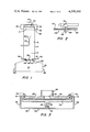
- FIG. 2 is an elevational view of a preferred embodiment of the invention
- FIG. 4 is an elevational view, on an enlarged scale and partly in section, showing half of the preferred embodiment.
- FIG. 5 is a hydraulic pressure profile of the embodiment shown in FIG. 2 through FIG. 4.
- a clarifying apparatus comprising a vessel 10 containing a vertically elongated clarification chamber 12.
- the clarifying chamber 12 includes a first or upper portion 14 contained within an annular vessel wall 16 and a second or lower portion 18 contained within the base or lower end 20 of the vessel 10 which is immediately below the cylindrical open lower end 22 of the chamber portion 14 and entirely open to communication with the lower end 22.
- a solid material or sludge discharge means designated generally as 32 is operatively associated with the upper end of the chamber upper portion for discharging separated solid material therefrom.
- the solid material discharge means 32 comprises an annular circumferential discharge chamber 34 provided with a discharge outlet 36 connected to a discharge conduit 38 which is open to the upper end of the chamber upper portion 14 and a rotary top scraper 40 which is rotatibly driven by a motor 42.
- the influent water supply means of the apparatus 10 comprises an influent water supply conduit 44 communicating with a source (not shown) of the influent water.
- the upper end of the conduit 44 terminates in an upwardly facing diffuser nozzle 46.
- the periphery of the chamber lower portion 18 is provided with liquid discharge outlets 48 arranged to discharge liquid from the lower end of the chamber lower portion 18.
- the influent water to be clarified is continuously generally upwardly supplied into the chamber upper portion 14 through the conduit 44 and diffuser nozzle 46.
- dissolved air-in-water from a source (not shown) is conducted through conduit 50 and exit from nozzles 49 as air bubbles.
- the scale and intensity of the fluid turbulence in the region of the nozzles 49 are controlled to provide good flocculation and bubble attachment conditions.
- Most of the bubbles cooperate to form a rising cloud of fine gas bubbles extending completely across the cross-section of the chamber upper portion 14 while the accompanying carrier liquid passes downwardly to the outlets 48.
- the rising cloud of fine air bubbles effect flotation separation of particles of solid material from the influent water, the flotation separated particles rising to the upper end of the chamber upper portion 14 to form a sludge blanket "S" discharged from the upper end by the discharge means 32.
- the liquid part of the influent water and any accompanying particles of solid material which are not flocculated adjacent the upper end of the chamber upper portion 14 flow downwardly in chamber upper portion 14 counter to the rising cloud of gaseous bubbles through the interstices or tortuous paths between the individual bubbles of the cloud.
- the new nozzle 49 includes a first member or disc 52 with a circular hole 54 (See FIG. 3) along its axis.
- the disc 52 is coaxial with the end of the conduit 50.
- the nozzle also includes a solid disc 56 axially spaced from the disc 52.
- the axial movement of the disc 56 away from the disc 52 is limited by a post 58 integral with and extending upwardly from a wire bracket 60.
- the post 58 extends snugly into a bore 62 extending upwardly from the lower end of a hub 64 of the floating disc 56.
- the bracket 60 includes two vertical portions 66 and 68 and inwardly turned portions 70 and 72 connected to the vertical portions 66 and 68 respectively. Portions 70 and 72 are bolted to the top of the disc 52 by means of bolts 74 and 76 respectively.
- the exit pressure from between the disc 52 and disc 56 may be, say about, 2 PSIG which is close to atmospheric pressure.
- the actual discharge pressure is a function of the depths of the nozzles in the flotation clarifier.
- the large supply pressure pushes to separate the floating disc 56 from the disc 52.
- the supply hole 54 is dimensioned as small as possible to minimize this separating force.
- the pressure is then dropped quickly to below ambient pressure by accelerating the fluid to a large radial velocity.
- the bowl shape contour of the disc 52 also avoids cavitation pressures.
- a negative pressure "A" (See FIG. 5) is maintained for a short radial distance to point "B". At point "B” we are starting to convert velocity energy back into pressure until we reach point "C".
- the bubbles issuing from between the two discs be uniformly small bubbles.
- One criteria for obtaining the uniform small bubbles of less than 100 microns diameter is that the pressure between the two discs not reach a very low absolute pressure.
- the lowest pressure, looking at FIG. 5, of course, is at points A, B and D.
- the base 80 of the recess or bowl 78 is no more than about 0.05 inches from the opposing surface of the floating disc 56 and the surface 82 forming the edge of the bowl or recess 78 no more than about 0.02 inches from the opposing surface of the floating disc 56.
- One preferred structure of the invention would include a pair of discs 52 and 56 having a radius of no more than about 6.5 inches with a surface 82 forming the edge of the bowl 78 of no more than about 1.0 inch from the outer periphery of the disc 52.
- a nozzle pressure of no more than about 100 PSIG the gap at point 82 would be about 0.02 inches and the gap of the surface 80 of the bowl 78 would be about 0.05 inches.
- Such a shaped nozzle produces a large amount of very fine bubbles of not more than about 100 microns in diameter.
- the figures show a recess or bowl shaped member in the disc 52 attached to the nozzle 50, if desired the disc 52 could have a flat bottom surface with the recess formed in the top of floating disc 56.
Abstract
The nozzle is used with a system for removing contaminants from a liquid including a source of dissolved air in water under pressure and includes a first member with a hole through which the dissolved air and water flows. A floating member is also provided. The shapes of the first member and the floating member are such that the hydraulic forces resulting from the flow of water outwardly between the two members causes the floating member to float a predetermined distance from the first member. The shortest distance separating the first member and the floating member is such that most bubbles exiting from between the two members have a diameter less than 100 microns.
Description
This is a continuation of application Ser. No. 970,552 filed Dec. 18, 1978 now abandoned.
This invention relates to systems for separating suspended solids from liquids by dissolved air flotation. More particularly, this invention is a new bubble generation and distribution device for use with a solids-liquid suspension system including a source of dissolved air in water under pressure.
Several processes are available to separate suspended solids from liquid. Filtration and centrifugation are the most frequently applied solid separation methods. This invention, however, is useful in the dissolved air flotation method of solid separation. In a dissolved air flotation unit the air is dissolved under pressure into the liquid. For example, at 80 PSI pressure and 30° C. about 7 times as much air can be dissolved than at atmospheric pressure. When the pressurized liquid is exposed to atmospheric pressure the excess air will come out of the pressurized liquid in the form of small air bubbles. The air bubbles collide with the suspended solid particles and become attached by absorption, entrapment and adhesion. The specific gravity of these particle-air bubble agglomerates is less than that of water so that they will rise to the surface forming a solid blanket. The clarified liquid is withdrawn from the tank as effluent.
For efficient operation of a dissolved air flotation unit, it is highly important that the bubbles coming out of the pressurized liquid are not too big. With smaller diameter bubbles, of course, more bubbles are formed for a given amount of air than with larger diameter bubbles thereby increasing the number of bubbles in a system for a given amount of air. Also, it has been found that when the bubbles become too large in diameter the small solids do not become attached to the bubbles and hence are not removed from the system. Most bubbles will range on the small side to about 30 microns in diameter and the major part of the bubbles should not exceed 100 microns.
Our new bubble generation and distribution nozzle produces bubbles with most of the bubbles having a diameter less than 100 microns.
The new invention is an apparatus for use in a system for removing contaminants from a liquid with this system including a source of dissolved air in water under pressure. The apparatus includes a first member having a hole through which the dissolved air-in-water flows. A solid member is also included in the apparatus. Means limit the axial movement of the solid member away from the first member while permitting axial movement of the solid member toward and away from the first member. Either the first member or the solid member has a recess formed on the surface facing the other member. The recess is shaped so that the hydraulic forces resulting from the flow of water outwardly between the two members are such that the solid member floats a predetermined distance from the first member. The shortest distance separating the first member and the solid member is such that most bubbles exiting between the two members have a diameter less than 100 microns.
The invention as well as its many advantages will be further understood by reference to the following detailed description and drawings in which:
FIG. 1 is an elevational view illustrating a flotation separator and showing the location of the new bubble generation and distribution nozzle in a flotation separator;
FIG. 2 is an elevational view of a preferred embodiment of the invention;
FIG. 3 is an elevational view, on an enlarged scale and partly in section, of the embodiment of FIG. 2.
FIG. 4 is an elevational view, on an enlarged scale and partly in section, showing half of the preferred embodiment; and
FIG. 5 is a hydraulic pressure profile of the embodiment shown in FIG. 2 through FIG. 4.
In the various figures, like parts are referred to by like numbers.
Referring to the drawings and more particularly to FIG. 1 a clarifying apparatus is shown comprising a vessel 10 containing a vertically elongated clarification chamber 12. The clarifying chamber 12 includes a first or upper portion 14 contained within an annular vessel wall 16 and a second or lower portion 18 contained within the base or lower end 20 of the vessel 10 which is immediately below the cylindrical open lower end 22 of the chamber portion 14 and entirely open to communication with the lower end 22.
A solid material or sludge discharge means designated generally as 32 is operatively associated with the upper end of the chamber upper portion for discharging separated solid material therefrom. The solid material discharge means 32 comprises an annular circumferential discharge chamber 34 provided with a discharge outlet 36 connected to a discharge conduit 38 which is open to the upper end of the chamber upper portion 14 and a rotary top scraper 40 which is rotatibly driven by a motor 42.
The influent water supply means of the apparatus 10 comprises an influent water supply conduit 44 communicating with a source (not shown) of the influent water. The upper end of the conduit 44 terminates in an upwardly facing diffuser nozzle 46.
The periphery of the chamber lower portion 18 is provided with liquid discharge outlets 48 arranged to discharge liquid from the lower end of the chamber lower portion 18.
During the operation of the apparatus, the influent water to be clarified is continuously generally upwardly supplied into the chamber upper portion 14 through the conduit 44 and diffuser nozzle 46. Simultaneously, dissolved air-in-water from a source (not shown) is conducted through conduit 50 and exit from nozzles 49 as air bubbles. The scale and intensity of the fluid turbulence in the region of the nozzles 49 are controlled to provide good flocculation and bubble attachment conditions. Most of the bubbles cooperate to form a rising cloud of fine gas bubbles extending completely across the cross-section of the chamber upper portion 14 while the accompanying carrier liquid passes downwardly to the outlets 48. The rising cloud of fine air bubbles effect flotation separation of particles of solid material from the influent water, the flotation separated particles rising to the upper end of the chamber upper portion 14 to form a sludge blanket "S" discharged from the upper end by the discharge means 32. The liquid part of the influent water and any accompanying particles of solid material which are not flocculated adjacent the upper end of the chamber upper portion 14 flow downwardly in chamber upper portion 14 counter to the rising cloud of gaseous bubbles through the interstices or tortuous paths between the individual bubbles of the cloud.
As shown in FIG. 2, FIG. 3 and FIG. 4, the new nozzle 49 includes a first member or disc 52 with a circular hole 54 (See FIG. 3) along its axis. The disc 52 is coaxial with the end of the conduit 50. The nozzle also includes a solid disc 56 axially spaced from the disc 52. The axial movement of the disc 56 away from the disc 52 is limited by a post 58 integral with and extending upwardly from a wire bracket 60. The post 58 extends snugly into a bore 62 extending upwardly from the lower end of a hub 64 of the floating disc 56. The bracket 60 includes two vertical portions 66 and 68 and inwardly turned portions 70 and 72 connected to the vertical portions 66 and 68 respectively. Portions 70 and 72 are bolted to the top of the disc 52 by means of bolts 74 and 76 respectively.
It is seen from the pressure diagram of FIG. 5 that there are two zones of positive pressure and two zones of negative pressure. The forces in these pressure zones plus the weight of the disc 56 must be carefully balanced to achieve a floating disc.
It is very important, of course, that the bubbles issuing from between the two discs be uniformly small bubbles. One criteria for obtaining the uniform small bubbles of less than 100 microns diameter is that the pressure between the two discs not reach a very low absolute pressure. The lowest pressure, looking at FIG. 5, of course, is at points A, B and D. In general, the base 80 of the recess or bowl 78 is no more than about 0.05 inches from the opposing surface of the floating disc 56 and the surface 82 forming the edge of the bowl or recess 78 no more than about 0.02 inches from the opposing surface of the floating disc 56. To achieve the smallest gap size for a given flow the following two requirements must be met:
(1) The point 82 of closest approach must be as close to the outside diameter as possible for maximum flow area and
(2) The velocity must be as high as possible through the gap 82.
One preferred structure of the invention would include a pair of discs 52 and 56 having a radius of no more than about 6.5 inches with a surface 82 forming the edge of the bowl 78 of no more than about 1.0 inch from the outer periphery of the disc 52. Thus at a nozzle pressure of no more than about 100 PSIG the gap at point 82 would be about 0.02 inches and the gap of the surface 80 of the bowl 78 would be about 0.05 inches. Such a shaped nozzle produces a large amount of very fine bubbles of not more than about 100 microns in diameter.
In operation, looking at FIG. 1, the influent suspended solids is fed to the vessel 10 by means of conduit 44 and diffuser 46 and then flows downwardly in vessel 10. The pressurized air-liquid is super-saturated with air and is fed into the vessel 10 through conduit 50 and outwardly from the nozzles 49. As the pressurized air-in-liquid flows outwardly from between the discs of the nozzles 49 the near atmospheric pressure (around 2 PSIG) causes the air to come out of solution in the form of micro sized bubbles. The influent suspended solids flow countercurrent to the rising air bubbles. The air bubbles mix with suspended particles and the particles become attached to the bubbles. The bubbles act as a screen and achieve solid-liquid separation by flotation. The sludge blanket "S" is formed at the top of the vessel 10 and is removed by the mechanical scraper 40 while the effluent is continuously removed from the bottom of the vessel by means of conduit 48.
The specially shaped nozzles provide a maximum amount of small tiny bubbles for a given amount of air with a minimum of those bubbles being over 100 microns in diameter.
Though the figures show a recess or bowl shaped member in the disc 52 attached to the nozzle 50, if desired the disc 52 could have a flat bottom surface with the recess formed in the top of floating disc 56.
Claims (6)
1. A liquid purifier for removing contaminants from a liquid, comprising: a vessel; conduits for conducting pressurized dissolved gas in water into the vessel; a first member connected to each conduit and having a hole through which the dissolved gas in water flows; a solid member normally axially-spaced a predetermined distance from the first member to provide empty space between the first member and the solid member, said solid member having a bore extending upwardly from its lower end; and means including a post extending snugly into said bore for normally supporting said solid member away from said first member while permitting axial movement only of said solid member toward said first member in response to the flow of water outwardly through said empty space, one of said first member and said solid member having a recess formed on the surface facing the other member, said hole in the first member being dimensioned and said recess being shaped so that the axial pressures and the radial velocities of the water flowing outwardly through said empty space are such that the solid member moves axially toward the first member and floats a predetermined distance from the first member, said predetermined distance being such that the surface forming the edge of the recess is no more than about 0.02 inches from the opposing surface of the other member so that bubbles are formed with most bubbles exiting from between the first member and the solid member having a diameter less than 100 microns.
2. An apparatus in accordance with claim 1 wherein the first member has the recess.
3. An apparatus in accordance with claim 2 wherein the first number is a disc with the hole along its axis, the solid member is a floating disc, and the recess is an annular recess extending outwardly from the hole.
4. An apparatus in accordance with claim 3 wherein the surface forming the annular recess is bowl-shaped.
5. An apparatus in accordance with claim 4 wherein the surface at the base of the bowl is no more than about 0.05 inches from the opposing surface of the floating disc.
6. An apparatus in accordance with claim 5 wherein the radius of each of the discs is no more than about 6.5 inches and the surface forming the edge of the bowl is no more than about 1.0 inch from the outer periphery of the first member.
Priority Applications (1)
| Application Number | Priority Date | Filing Date | Title |
|---|---|---|---|
| US06/159,869 US4338192A (en) | 1978-12-18 | 1980-06-16 | Clarifier bubble generation and distribution nozzle |
Applications Claiming Priority (2)
| Application Number | Priority Date | Filing Date | Title |
|---|---|---|---|
| US97055278A | 1978-12-18 | 1978-12-18 | |
| US06/159,869 US4338192A (en) | 1978-12-18 | 1980-06-16 | Clarifier bubble generation and distribution nozzle |
Related Parent Applications (1)
| Application Number | Title | Priority Date | Filing Date |
|---|---|---|---|
| US97055278A Continuation | 1978-12-18 | 1978-12-18 |
Publications (1)
| Publication Number | Publication Date |
|---|---|
| US4338192A true US4338192A (en) | 1982-07-06 |
Family
ID=26856392
Family Applications (1)
| Application Number | Title | Priority Date | Filing Date |
|---|---|---|---|
| US06/159,869 Expired - Lifetime US4338192A (en) | 1978-12-18 | 1980-06-16 | Clarifier bubble generation and distribution nozzle |
Country Status (1)
| Country | Link |
|---|---|
| US (1) | US4338192A (en) |
Cited By (19)
| Publication number | Priority date | Publication date | Assignee | Title |
|---|---|---|---|---|
| EP0130943A2 (en) * | 1983-07-01 | 1985-01-09 | Elsa Margrit Perren-Blatti | Process for the continuous separation of material from a polluted liquid containing tensides |
| US4534955A (en) * | 1983-07-01 | 1985-08-13 | Chevron Research Company | Sulfur extraction process |
| US4551246A (en) * | 1982-09-30 | 1985-11-05 | International Resources Management, Inc. | Flotation apparatus utilizing a novel floc barrier and current diverting means |
| US4673494A (en) * | 1984-06-27 | 1987-06-16 | Lenox Institute For Research, Inc. | Water treatment apparatus |
| US4690756A (en) * | 1985-05-15 | 1987-09-01 | Ry Charles D Van | Apparatus for microaquaculture and pollution control |
| US4795557A (en) * | 1986-06-18 | 1989-01-03 | Otv (Omnium De Traitements Et De Valorisation) | Apparatus for gas transfer and flotation for treating water to be purified |
| US4935148A (en) * | 1985-05-15 | 1990-06-19 | Ry Charles D Van | Process for microaquaculture and pollution control |
| US4986903A (en) * | 1988-10-11 | 1991-01-22 | Canzoneri Anthony S | Induced static single flotation cell |
| US5011597A (en) * | 1988-10-11 | 1991-04-30 | Canzoneri Anthony S | Single cell vertical static flow flotation unit |
| US5080780A (en) * | 1988-10-11 | 1992-01-14 | Process Development Company | Single cell vertical static flow flotation unit cross-reference to related applications |
| US5151177A (en) * | 1990-05-10 | 1992-09-29 | Darling-Delaware Company, Inc. | Method and apparatus for dissolved air flotation with aeration |
| EP0514800A2 (en) * | 1991-05-22 | 1992-11-25 | Klöckner-Humboldt-Deutz Aktiengesellschaft | Device for pneumatic flotation |
| US5310485A (en) * | 1992-09-30 | 1994-05-10 | Darling-Delaware Company, Inc. | Process for dissolved gas flotation in anaerobic wastewater treatment |
| US5356533A (en) * | 1992-05-14 | 1994-10-18 | F. Tecs Co., Ltd. | Bubbling system |
| WO1996022251A1 (en) * | 1995-01-19 | 1996-07-25 | Hans Eriksson | Apparatus for distribution and dispersion of air saturated water |
| US6293529B1 (en) * | 2000-06-01 | 2001-09-25 | Tsun Shin Chang | Bubble generating apparatus |
| US20040173538A1 (en) * | 2002-07-18 | 2004-09-09 | Stewart Timothy L. | Process for treating waste to remove contaminants |
| US20120138482A1 (en) * | 2010-12-01 | 2012-06-07 | Premier Tech Technologies Ltee | Self-cleaning electro-reaction unit for wastewater treatment and related process |
| US20120211407A1 (en) * | 2011-02-17 | 2012-08-23 | Sionix Corporation | Dissolved Air Flotation Nozzle for Use With Self Contained Dissolved Air Flotation System |
Citations (3)
| Publication number | Priority date | Publication date | Assignee | Title |
|---|---|---|---|---|
| US3846299A (en) * | 1972-12-13 | 1974-11-05 | Improved Machinery Inc | Clarifying apparatus and method for influent waters |
| US3958760A (en) * | 1974-10-23 | 1976-05-25 | Peretz Rosenberg | Spray nozzle |
| US4040975A (en) * | 1976-02-03 | 1977-08-09 | Goldwell Gmbh Chemische Fabrik H.E. Dotter | Foam generator for foaming liquids |
-
1980
- 1980-06-16 US US06/159,869 patent/US4338192A/en not_active Expired - Lifetime
Patent Citations (3)
| Publication number | Priority date | Publication date | Assignee | Title |
|---|---|---|---|---|
| US3846299A (en) * | 1972-12-13 | 1974-11-05 | Improved Machinery Inc | Clarifying apparatus and method for influent waters |
| US3958760A (en) * | 1974-10-23 | 1976-05-25 | Peretz Rosenberg | Spray nozzle |
| US4040975A (en) * | 1976-02-03 | 1977-08-09 | Goldwell Gmbh Chemische Fabrik H.E. Dotter | Foam generator for foaming liquids |
Cited By (25)
| Publication number | Priority date | Publication date | Assignee | Title |
|---|---|---|---|---|
| US4551246A (en) * | 1982-09-30 | 1985-11-05 | International Resources Management, Inc. | Flotation apparatus utilizing a novel floc barrier and current diverting means |
| EP0130943A2 (en) * | 1983-07-01 | 1985-01-09 | Elsa Margrit Perren-Blatti | Process for the continuous separation of material from a polluted liquid containing tensides |
| US4534955A (en) * | 1983-07-01 | 1985-08-13 | Chevron Research Company | Sulfur extraction process |
| EP0130943A3 (en) * | 1983-07-01 | 1986-04-16 | Benno Perren | Process for the continuous separation of material from a polluted liquid containing tensides |
| US4673494A (en) * | 1984-06-27 | 1987-06-16 | Lenox Institute For Research, Inc. | Water treatment apparatus |
| US4690756A (en) * | 1985-05-15 | 1987-09-01 | Ry Charles D Van | Apparatus for microaquaculture and pollution control |
| US4935148A (en) * | 1985-05-15 | 1990-06-19 | Ry Charles D Van | Process for microaquaculture and pollution control |
| US4795557A (en) * | 1986-06-18 | 1989-01-03 | Otv (Omnium De Traitements Et De Valorisation) | Apparatus for gas transfer and flotation for treating water to be purified |
| US4986903A (en) * | 1988-10-11 | 1991-01-22 | Canzoneri Anthony S | Induced static single flotation cell |
| US5011597A (en) * | 1988-10-11 | 1991-04-30 | Canzoneri Anthony S | Single cell vertical static flow flotation unit |
| US5080780A (en) * | 1988-10-11 | 1992-01-14 | Process Development Company | Single cell vertical static flow flotation unit cross-reference to related applications |
| US5151177A (en) * | 1990-05-10 | 1992-09-29 | Darling-Delaware Company, Inc. | Method and apparatus for dissolved air flotation with aeration |
| EP0514800A2 (en) * | 1991-05-22 | 1992-11-25 | Klöckner-Humboldt-Deutz Aktiengesellschaft | Device for pneumatic flotation |
| EP0514800A3 (en) * | 1991-05-22 | 1995-02-22 | Kloeckner Humboldt Deutz Ag | Device for pneumatic flotation |
| US5356533A (en) * | 1992-05-14 | 1994-10-18 | F. Tecs Co., Ltd. | Bubbling system |
| US5310485A (en) * | 1992-09-30 | 1994-05-10 | Darling-Delaware Company, Inc. | Process for dissolved gas flotation in anaerobic wastewater treatment |
| WO1996022251A1 (en) * | 1995-01-19 | 1996-07-25 | Hans Eriksson | Apparatus for distribution and dispersion of air saturated water |
| WO1996022249A1 (en) * | 1995-01-19 | 1996-07-25 | Norrtaelje Kommun Tekniska Kon | Container for liquid with dispersion device |
| US6017449A (en) * | 1995-01-19 | 2000-01-25 | Eriksson; Hans | Container for liquid with dispersion device |
| US6293529B1 (en) * | 2000-06-01 | 2001-09-25 | Tsun Shin Chang | Bubble generating apparatus |
| US20040173538A1 (en) * | 2002-07-18 | 2004-09-09 | Stewart Timothy L. | Process for treating waste to remove contaminants |
| US7344647B2 (en) | 2002-07-18 | 2008-03-18 | Stewart Water Solutions, Ltd. | Process for treating waste water to remove contaminants |
| US20120138482A1 (en) * | 2010-12-01 | 2012-06-07 | Premier Tech Technologies Ltee | Self-cleaning electro-reaction unit for wastewater treatment and related process |
| US9216918B2 (en) * | 2010-12-01 | 2015-12-22 | Premier Tech Technologies Ltee | Self-cleaning electro-reaction unit for wastewater treatment and related process |
| US20120211407A1 (en) * | 2011-02-17 | 2012-08-23 | Sionix Corporation | Dissolved Air Flotation Nozzle for Use With Self Contained Dissolved Air Flotation System |
Similar Documents
| Publication | Publication Date | Title |
|---|---|---|
| US4338192A (en) | Clarifier bubble generation and distribution nozzle | |
| US5300222A (en) | Water clarification method and apparatus | |
| US5462669A (en) | Method for dissolved air floatation and similar gas-liquid contacting operations | |
| US5492622A (en) | Water clarification apparatus | |
| US2695710A (en) | Flotation and clarification apparatus | |
| US4011158A (en) | Oil-water separation process and apparatus | |
| WO1992003219A1 (en) | Aeration apparatus with diffuser | |
| HU215329B (en) | Cyclone with double acting extraction system, and method for a biological water-treating | |
| US4127488A (en) | Method and apparatus for separating solids from liquids | |
| WO2008037086A1 (en) | Apparatus and method for efficient particle to gas bubble attachment in a slurry | |
| AU615728B2 (en) | Settling vessel for an activated-sludge/sewage suspension | |
| AU2992197A (en) | Three zone dissolved air flotation clarifier with improved efficiency | |
| US3870635A (en) | Apparatus for clarifying an influent water | |
| US5160610A (en) | Radial header for dissolved air flotation systems | |
| FI62657C (en) | ADJUSTMENT FOR CLARIFICATION OF VAT | |
| US4070277A (en) | Apparatus for separating solids from liquids | |
| CA1136779A (en) | Bubble generation and distribution nozzle | |
| US4553990A (en) | Device for separating gaseous and liquid components from a foamy gas liquid mixture | |
| CA2069959A1 (en) | Method and apparatus for separation by flotation in a centrifugal field | |
| EP0625074B1 (en) | Vortex flocculation of solids suspended in liquid | |
| US5116492A (en) | Apparatus for clarification of industrial sewage | |
| JP2022024796A (en) | Pressurized flotation separation apparatus | |
| JP3309759B2 (en) | Pressure flotation device | |
| JP3508571B2 (en) | Pressure flotation device | |
| GB2232097A (en) | Flotation apparatus |
Legal Events
| Date | Code | Title | Description |
|---|---|---|---|
| STCF | Information on status: patent grant |
Free format text: PATENTED CASE |