US4333170A - Acoustical detection and tracking system - Google Patents
Acoustical detection and tracking system Download PDFInfo
- Publication number
- US4333170A US4333170A US05/853,207 US85320777A US4333170A US 4333170 A US4333170 A US 4333170A US 85320777 A US85320777 A US 85320777A US 4333170 A US4333170 A US 4333170A
- Authority
- US
- United States
- Prior art keywords
- signals
- phase difference
- microphones
- frequency
- target
- Prior art date
- Legal status (The legal status is an assumption and is not a legal conclusion. Google has not performed a legal analysis and makes no representation as to the accuracy of the status listed.)
- Expired - Lifetime
Links
Images


Classifications
-
- G—PHYSICS
- G01—MEASURING; TESTING
- G01S—RADIO DIRECTION-FINDING; RADIO NAVIGATION; DETERMINING DISTANCE OR VELOCITY BY USE OF RADIO WAVES; LOCATING OR PRESENCE-DETECTING BY USE OF THE REFLECTION OR RERADIATION OF RADIO WAVES; ANALOGOUS ARRANGEMENTS USING OTHER WAVES
- G01S3/00—Direction-finders for determining the direction from which infrasonic, sonic, ultrasonic, or electromagnetic waves, or particle emission, not having a directional significance, are being received
- G01S3/80—Direction-finders for determining the direction from which infrasonic, sonic, ultrasonic, or electromagnetic waves, or particle emission, not having a directional significance, are being received using ultrasonic, sonic or infrasonic waves
- G01S3/802—Systems for determining direction or deviation from predetermined direction
- G01S3/808—Systems for determining direction or deviation from predetermined direction using transducers spaced apart and measuring phase or time difference between signals therefrom, i.e. path-difference systems
-
- G—PHYSICS
- G01—MEASURING; TESTING
- G01S—RADIO DIRECTION-FINDING; RADIO NAVIGATION; DETERMINING DISTANCE OR VELOCITY BY USE OF RADIO WAVES; LOCATING OR PRESENCE-DETECTING BY USE OF THE REFLECTION OR RERADIATION OF RADIO WAVES; ANALOGOUS ARRANGEMENTS USING OTHER WAVES
- G01S3/00—Direction-finders for determining the direction from which infrasonic, sonic, ultrasonic, or electromagnetic waves, or particle emission, not having a directional significance, are being received
- G01S3/80—Direction-finders for determining the direction from which infrasonic, sonic, ultrasonic, or electromagnetic waves, or particle emission, not having a directional significance, are being received using ultrasonic, sonic or infrasonic waves
- G01S3/8006—Multi-channel systems specially adapted for direction-finding, i.e. having a single aerial system capable of giving simultaneous indications of the directions of different signals
Definitions
- This invention relates to the passive detection and tracking of targets which radiate acoustical energy, and more particularly to such a system which performs these functions by digital processing techniques.
- passive detection and tracking of targets such as aircraft and ground vehicles which emit acoustical energy
- passive systems do not radiate a signal which can be used to indicate the presence as well as the location and identity of the tracking station.
- active detection and tracking systems are subject to the reception of false "echoes" by virtue of multiple reflections.
- active tracking systems are more subject to counter measures than passive systems, which can completely obviate their effectiveness.
- the system of the present invention provides an acoustical detection and tracking system which overcomes the aforementioned shortcomings of the prior art in that it enables the positive identification and grouping of signals emanating from a common target such that errors in tracking targets can be minimized. Further, in view of the accurate grouping of all signals emanating from a particular target provided in the system of the present invention, it is possible to identify targets by virtue of a characteristic frequency pattern in their acoustical energy.
- the system of the invention generates information as to elevation and azimuth of the identified target to enable the tracking thereof by means of digital processing which can be performed in a special or general purpose digital computer.
- FIG. 1 is a block diagram showing the basic components of the system of the invention
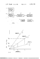
- FIG. 2 is a graphic illustration of the generation of the phase slope difference in the system of the invention.
- FIG. 3 is a pictorial view of a microphone array which may be utilized in the system of the invention.
- FIG. 4 is a functional block diagram illustrating a preferred embodiment of portions of the system of the invention involved with detection, multiplexing and converting the received signals from analog to digital form;
- FIG. 5 is a functional block diagram illustrating the fast Fourier transformer of the preferred embodiment
- FIGS. 6A-6F are a series of waveform diagrams illustrating signals generated in the system of the invention.
- FIGS. 7A-7C are a series of graphical illustrations showing various digital signals generated in the system of the invention.
- the system of the invention is as follows: Acoustical transducers such as microphones are arranged in an array so as to receive acoustical signals from targets generating acoustical energy. Pairs of the microphones are arranged in a mutually orthogonal relationship to enable the generation of information as to the azimuth and elevation of the target by virtue of the phase difference between signals received by each of the paired microphones. The outputs of the microphones are sequentially sampled and these sampled signals are time multiplexed, the time multiplexed signals then being converted from analog to digital form in analog/digital converter.
- Acoustical transducers such as microphones are arranged in an array so as to receive acoustical signals from targets generating acoustical energy. Pairs of the microphones are arranged in a mutually orthogonal relationship to enable the generation of information as to the azimuth and elevation of the target by virtue of the phase difference between signals received by each of the paired microphones.
- the outputs of the microphones are sequentially sampled and
- the output of the analog/digital converter is fed to a fast Fourier transformer (FFT) which transforms the signals into Fourier transform coefficients broken down into real and imaginary components so that phase information on each of the frequency bins is retained.
- FFT fast Fourier transformer
- the output of the fast Fourier transformer is fed to a digital processor, which first computes the power and phase angle for each frequency bin for each microphone, and then determines from the power level of the frequency bins which of these contain signal data of interest and which do not, so that the frequency bins of interest can be separated out. Then the phase differences between frequency bins of interest from pairs of microphones are computed. These phase differences are then divided by the frequency associated with their bins, thereby determining the phase difference slope for each frequency bin. Signals having common phase difference slopes are then grouped together, these common slopes indicating signals originating at common targets. The azimuth and elevation of each target can then be computed from the phase difference slopes for the paired azimuth and elevation microphones respectively.
- FIG. 1 a functional block diagram of the system of the invention is shown.
- Acoustical signals are received by acoustical transducers and filters 11.
- the transducers may comprise an array of microphones arranged in pairs so as to be capable of providing information as to the azimuth and elevation of targets, as shown for example in FIG. 3.
- Band pass filtering is accomplished to eliminate noise and other signals which are not of interest.
- the signals are then fed to sampling and multiplexing circuits 12.
- the outputs of the microphones are sequentially sampled in the sampling portion of the circuit and these outputs are then time multiplexed together to form a composite signal including outputs from all microphones.
- the signal is then converted from analog to digital form in analog/digital converter 13.
- the output of analog/digital converter 13 is fed to fast Fourier transformer 15 which operates in accordance with an appropriate algorithm, such as the one cited further on in the specification.
- the fast Fourier transform transforms the signal into real and imaginary Fourier coefficients for each frequency bin and for each microphone.
- the real and imaginary Fourier coefficients are fed to digital processor 17 which operates to compute the phase differences between the signals received by pairs of microphones for each frequency bin, these phase difference signals being divided by the frequency bin of the associated bin to provide a phase difference slope for each such signal. Signals having common phase difference slopes are then grouped together, each of these groups representing signals emanating from a common target.
- the magnitudes of the slopes for signals obtained from a pair of "azimuth” microphones provide information as to the azimuth of the target and signals from a pair of "elevation” microphones provide information as to target elevation.
- the elevation microphones can be placed ahead of the azimuth microphones so that the target direction ahead or behind can be resolved by comparing one elevation microphone to the azimuth microphone data.
- Information as to azimuth, elevation and the frequencies of signals emanated by each target is fed to readout device 18.
- ⁇ f 1 m 1 phase of f 1 at microphone #1 of the pair
- ⁇ f 2 m 2 phase of f 2 at microphone #2
- ⁇ f 2 m 1 phase of f 2 at microphone #1
- ⁇ f n m 2 phase of f n at microphone #2
- ⁇ f n m 1 phase of f n at microphone #1
- f 1 , f 2 -f n are frequencies of signals emanating from a common target.
- phase difference slope lines 20-22 each represent a common phase difference slope for all signals emanating from a particular target, regardless of the frequencies of such signals.
- slope line 20 represents signals from a first target
- slope line 21 signals from a second target
- slope line 22 signals from an "nth" target.
- This characteristic phase difference slope condition is employed in the system of the invention for identifying and grouping signals from a common target.
- These signals can be grouped and their phase difference slope characteristics used to compute the azimuth and elevation of each target which information can be further used to track the target.
- the frequency composition of the grouped signals can be used to identify the target by virtue of the known characteristic frequency compositions of signals generated by various types of targets.
- a typical microphone array that can be utilized in the system of the invention is illustrated.
- a first pair of microphones 25 and 26 are mounted in spaced relationship along a horizontal axis to provide azimuth information, while a second pair of microphones 28 and 29 are mounted along a vertical axis substantially normal to and forward of that for the first pair, so as to provide elevation information.
- the microphones may be of either the condenser or piezoelectric type wherein phase delay as a function of frequency and wave front direction is essentially the same for each microphone. Microphone sensitivity, dynamic range and phase accuracy requirements may vary with the particular application requirements at hand. Spacing between the pairs of microphones is typically 15 to 36 inches.
- FIGS. 4, 6A-6F and 7A a preferred embodiment of the transducer, filtering, multiplexing and analog to digital conversion circuitry of the system of the invention along with waveform diagrams pertinent thereto are shown.
- Microphones 25-29 receive signals which are amplified in amplifiers 35-38 respectively.
- Amplifiers 35-38 have automatic gain control circuits incorporated therein.
- the outputs of amplifiers 35-38 are illustrated in FIG. 6A and generally have frequency components therein from 5 Hz to 20 kHz, with the dominant portions being of the order of 30-250 hertz.
- band pass filters 39-42 which operate to filter out the low frequency and high frequency components of the signals, leaving signals between 10 and 250 hertz as illustrated in FIG. 6B.
- Such filtering is directed principally to eliminate wind induced noise at the low frequencies and aliasing inputs at the high frequencies, and also eliminate other frequencies which are not of interest.
- the outputs of filters 39-42 are fed to sample-hold circuits 44-47 respectively.
- the sample-hold circuits operate in response to sampling timing control 50 which may be timed by a 512 hertz clock signal.
- Sampling timing control 50 is also used to control the operation of multiplexer 52, which time multiplexes the outputs of the sample-hold circuits.
- the sample-hold circuits are simultaneously placed in a "hold" mode, while multiplexer 52 sequences through all four of the sample-hold outputs while the signals are being digitized in the analog to digital converter. When the last output has been digitized, the sample-holds are placed back in the sample mode.
- the outputs of the sample-hold circuits are illustrated in FIG. 6C, while the output of the multiplexer is shown in FIG. 6D.
- the output of multiplexer 52 is fed to absolute value amplifier 53, which operates to effectively flip over all the negative portions of the signals to produce a unipolar output, as shown in FIG. 6E.
- a "sign" signal is fed to multiplexer 60 to indicate negative values when they appear.
- the output of amplifier 53 is fed to digital/analog multiplier 54.
- Multiplier 54 receives a weighting function from ROM 56, this ROM operating in response to counter 57 which in turn responds to sampling timing control 50.
- Multiplier 54 provides Hamming function weighting to the input samples. This type of programmed weighting as is well known in the art builds up the amplitude of the signals near the midpoint of the timing interval which facilitates discrimination of the signals. This can be seen in FIG.
- FIG. 6F which shows the output of multiplier 54.
- the output of multiplier 54 is fed to analog/digital converter 58 which converts the signals to binary digital form as shown in FIG. 7A.
- the output of analog/digital converter 58 is fed to multiplexer 60 where the signals are time multiplexed ordered for storage in RAMs 73 and 74 in a manner suitable for processing in accordance with the FFT algorithm.
- FIG. 5 a fast Fourier transformer unit which may be used in the system of the invention is schematically illustrated.
- Outputs are alternately fed from multiplexer 60 (FIG. 4) to RAM 73 and RAM 74 of the transformer unit.
- RAMs 73 and 74 are used to hold all intermediate real values computed in each pass of the FFT process.
- RAMs 70 and 71 are used to hold the computed imaginary values. During the "dumping" time, these last mentioned RAMs are loaded with all zeros.
- the outputs of RAMs 70, 71, or 73 and 74 are alternately fed to multiplexer 80. Also fed to multiplexer 80 is the output of ROM 82 which contains sine/cosine values for one quadrant.
- the multiplexed signals are fed from multiplexer 80 to real arithmetic unit 84 and imaginary arithmetic unit 85.
- Each arithmetic unit contains temporary storage registers, complementers, an adder and shift registers. By the use of proper control and timing signals, these arithmetic units perform all of the complex multiplications and additions required in the FFT operation.
- the control and timing instructions are supplied by high speed ROM 87 containing the "micro instructions" for the FFT operation.
- the operation of the FFT microprogram is such that while each arithmetic unit is processing data from one of the microphone channels, the computed data from the previous calculation is being stored back in memory and new data for the next calculation is being fetched from memory.
- the FFT address logic 90 operates in response to microprogram 87 to control the addressing of RAMs 79, 71, 73 and 74, and ROM 82.
- address counter 91 Associated with microprogram ROM 87 is address counter 91.
- the address counter 91 normally sequences the ROM to the next higher micro instruction with each clock pulse. However, certain of the ROM output bits are fed back to the address counter allowing the microprogram to conditionally jump anywhere in the micro instruction sequence.
- the fast Fourier transform unit operates in accordance with a conventional FFT algorithm which is contained in the programs of ROM 87 and ROM 82.
- FIG. 5 A typical such algorithm which may be employed is described, for example, in Digital Processing of Signals by B. Gold and C. M. Rader, published by McGraw Hill, 1969. It is to be noted that the circuitry of FIG. 5 is only one of many implementations which may be utilized for computing the Fourier coefficients, and other circuits and techniques including the use of a general purpose computer, such as an IBM-370, may be employed if so desired.
- Typical final real and imaginary Fourier coefficient values residing in "real" random access memories 73, 74 and “imaginary" random access memories 70 and 71 are respectively shown in FIGS. 7B and 7C. As can be seen, these values are stored in binary digital form and represent the real and imaginary components of the microphone outputs for each microphone and for each frequency bin.
- the Fourier coefficients are fed to a digital processor which may comprise a general purpose computer such as the IBM Model 370 wherein the signals are digitally processed.
- a digital processor which may comprise a general purpose computer such as the IBM Model 370 wherein the signals are digitally processed.
- the following functions are sequentially performed in the computer:
- the algorithm set forth below provides the programming information for implementing the above indicated functions, and, as noted, may be used in programming a general purpose digital computer to derive the desired outputs.
- the system of this invention thus provides means for accurately detecting, tracking and identifying targets by virtue of the acoustical energy radiated by such targets, this end result being achieved by digital processing.
Abstract
Description
______________________________________
DICTIONARY OF TERMS USED IN ALGORITHM
______________________________________
AZIMUTH -   Bearing angle
BIN -       Current Fourier bin number
CHECK -     Calculated value used to check powers
CONFIG -    Configuration of sensors
CYCLES -    Cycles per second per Fourier bin
DELTA -     Fractional seconds between measurements
DIFF -      Current difference between phase angles
DVATE -     Allowable deviation in power between
            mikes
ELEVATION - Elevation/Depression angle
FINI -      Finish time of data file info to be used
FFT -       Fast Fourier Transform Process
            (converts signal from time into
            frequency domain)
FREQ -      Current cycles per second value
FREQ L -    Lowest frequency of interest
FREQ H -    Highest frequency of interest
GROUP -     Phase difference grouping tolerance
HCONES (n) -
            Array containing horizontal mike pair
            cone angles
HCPS(n) -   Array containing frequencies of Fourier
            bins selected in horizontal mike pair
            processing
HDIST -     Horizontal mike pair spacing distance
HFACTR -    Calculated horizontal mike pair spacing
            factor
HIBIN -     Highest Fourier bin number of interest
HINDEX(n,m) -
            Array containing bin numbers selected
            in horizontal mike pair slope grouping
            process
HLIMIT -    Calculated maximum value of valid slopes
            in the horizontal mike pair process
HPWR(n) -   Array containing power values selected
            in horizontal mike pair direction
            processing
HSLOPE(n) - Array containing phase difference slopes
            selected in horizontal mike pair direc-
            tion processing
HTOLER -    Calculated sine value of horizontal
            mike pair slope grouping tolerance
I -         Temporary Imaginary portion of
            complex value
LOBIN -     Lowest Fourier bin number of interest
LOWER -     Lower bound of current slope group
MATCHD(n,m) -
            Array containing matched horizontal
            and vertical mike pair cone angle
            indices
MAX BIN -   Current bin number containing MAXPWR
MAX PWR -   Current highest power value
MIKE -      Temporary index of mike numbers
            (Mikes 1 & 2 = horizontal, 3 & 4 =
            vertical)
NBINH -     Temporary index for horizontal mike
            pair bins
NBINV -     Temporary index for vertical mike pair
            bins
NGRPH -     Temporary index for horizontal mike
            pair groups
NGRPV -     Temporary index for vertical mike pair
            groups
NHBINS(m) - Array containing quantity of bins
            involved in a horizontal mike pair group
NHGRPS -    Quantity of horizontal mike pair groups
NHITS -     Quantity of matching frequencies between
            current horizontal and vertical cone
            angle groups
NHSIGS -    Quantity of signals which passed power
            screening in horizontal mike pair
            processing
NPTS -      Quantity of measurements per mike
NVBINS(n) - Array containing quantity of bins
            involved in a vertical mike pair group
NVGRPS -    Quantity of vertical mike pair groups
NVSIGS -    Quantity of signals which passed power
            screening in vertical mike pair
            processing
POWER(n,m) -
            Array containing calculated signal
            power for each bin and mike
R -         Temporary Real portion of complex value
SCALE -     Calculated scalar
SHLDR -     Required power roll-off between bins
SLOPE -     Current phase difference slope
START -     Starting time of data file info to be
            used
STEP -      Starting time increment between process
            iterations
SUM -       Temporary accumulation of slope values
THETA(n,m) -
            Array containing calculated signal
            phase angles for each bin and mike
THRESH -    Minimum acceptable signal power
UPPER -     Upper bound of current slope group
VCONES(m) - Array containing vertical mike pair
            cone angles
VCPS(n) -   Array containing frequencies of Fourier
            bins selected in vertical mike pair
            processing
VDIST -     Vertical mike pair spacing distance
VFACTR -    Calculated vertical mike pair spacing
            factor
VINDEX(m,m) -
            Array containing bin numbers selected
            in vertical mike pair slope grouping
            process
VLIMIT -    Calculated maximum value of valid slopes
            in the vertical mike pair process
VPWR (n) -  Array containing power values selected
            in vertical mike pair direction pro-
            cessing
VSLOPE(n) - Array containing phase difference slopes
            selected in vertical mike pair direction
            processing
VTOLER -    Calculated sine value of vertical mike
            pair slope grouping tolerance
X, Y -      Temporary values used during azimuth
            and elevation calculations
______________________________________
 ##STR1##
Claims (13)
Priority Applications (1)
| Application Number | Priority Date | Filing Date | Title |
|---|---|---|---|
| US05/853,207 US4333170A (en) | 1977-11-21 | 1977-11-21 | Acoustical detection and tracking system |
Applications Claiming Priority (1)
| Application Number | Priority Date | Filing Date | Title |
|---|---|---|---|
| US05/853,207 US4333170A (en) | 1977-11-21 | 1977-11-21 | Acoustical detection and tracking system |
Publications (1)
| Publication Number | Publication Date |
|---|---|
| US4333170A true US4333170A (en) | 1982-06-01 |
Family
ID=25315371
Family Applications (1)
| Application Number | Title | Priority Date | Filing Date |
|---|---|---|---|
| US05/853,207 Expired - Lifetime US4333170A (en) | 1977-11-21 | 1977-11-21 | Acoustical detection and tracking system |
Country Status (1)
| Country | Link |
|---|---|
| US (1) | US4333170A (en) |
Cited By (62)
| Publication number | Priority date | Publication date | Assignee | Title |
|---|---|---|---|---|
| EP0125838A2 (en) * | 1983-05-11 | 1984-11-21 | Racal Communications Equipment Limited | Direction finding |
| EP0137745A2 (en) * | 1983-10-07 | 1985-04-17 | Racal Research Limited | Direction finding systems |
| US4586195A (en) * | 1984-06-25 | 1986-04-29 | Siemens Corporate Research & Support, Inc. | Microphone range finder |
| US4741038A (en) * | 1986-09-26 | 1988-04-26 | American Telephone And Telegraph Company, At&T Bell Laboratories | Sound location arrangement |
| DE3808983A1 (en) * | 1987-03-21 | 1988-10-06 | Ferranti Plc | DEVICE FOR GENERATING A MULTIPLE OF ACOUSTIC ENERGY SPECTRA |
| US4955003A (en) * | 1984-06-04 | 1990-09-04 | The United States Of America As Represented By The Secretary Of The Navy | Phase accumulator-bearing tracker |
| DE3817627A1 (en) * | 1988-05-25 | 1991-09-05 | Telefunken Systemtechnik | Direction finding arrangement for passive acoustic location of target - evaluates transition time by passing electrical signals of acoustic sensors via filters, sampling circuits, multiplexer |
| EP0451649A2 (en) * | 1990-04-10 | 1991-10-16 | Ruble, Earl H. | Method and apparatus for determining the location of a sound source |
| US5099456A (en) * | 1990-06-13 | 1992-03-24 | Hughes Aircraft Company | Passive locating system |
| WO1993007506A1 (en) * | 1991-10-11 | 1993-04-15 | Incastec Associates Ltd. | Feature location and display apparatus |
| FR2687496A1 (en) * | 1992-02-18 | 1993-08-20 | Alcatel Radiotelephone | METHOD FOR REDUCING ACOUSTIC NOISE IN A SPEECH SIGNAL |
| FR2689270A1 (en) * | 1992-03-23 | 1993-10-01 | Hughes Aircraft Co | Three-dimensional tracking from maximum to posterior (MAP). |
| FR2690261A1 (en) * | 1992-03-23 | 1993-10-22 | Hughes Aircraft Co | Signal processing incorporating signal estimation and signal elimination methods using a posterior maximum algorithm, and sequential signal detection. |
| EP0612059A2 (en) * | 1992-12-23 | 1994-08-24 | Daimler-Benz Aktiengesellschaft | Method for estimating the propagation time in noisy speech channels |
| GB2298278A (en) * | 1995-02-21 | 1996-08-28 | Israel State | Detecting the direction and location of noise sources |
| WO1996029612A1 (en) * | 1995-03-20 | 1996-09-26 | Aktsionernoe Obschestvo Zakrytogo Tipa 'itf Intersvyaz' | Method of determining the bearings of aquatic organisms and a device for carrying out the said method |
| US5568154A (en) * | 1995-05-22 | 1996-10-22 | State Of Israel-Ministry Of Defense Armament Development Authority-Rafael | System and a method for the instantaneous determination of the frequencies and angles of arrival of simultaneously incoming RF signals |
| US5581620A (en) * | 1994-04-21 | 1996-12-03 | Brown University Research Foundation | Methods and apparatus for adaptive beamforming |
| WO1997037194A1 (en) * | 1996-03-29 | 1997-10-09 | Appelgren Haakan | Method and device for projectile measurements |
| DE19634093C1 (en) * | 1996-08-23 | 1997-10-16 | Stn Atlas Elektronik Gmbh | Determination of signal content of pulse radiated by sonar equipment |
| US6141293A (en) * | 1997-10-30 | 2000-10-31 | Netmor Ltd. | Ultrasonic positioning and tracking system |
| US6236313B1 (en) | 1997-10-28 | 2001-05-22 | Pittway Corp. | Glass breakage detector |
| US20020114531A1 (en) * | 2001-02-16 | 2002-08-22 | Torunoglu Ilhami H. | Technique for removing blurring from a captured image |
| US20030156756A1 (en) * | 2002-02-15 | 2003-08-21 | Gokturk Salih Burak | Gesture recognition system using depth perceptive sensors |
| US20030165048A1 (en) * | 2001-12-07 | 2003-09-04 | Cyrus Bamji | Enhanced light-generated interface for use with electronic devices |
| US20030169906A1 (en) * | 2002-02-26 | 2003-09-11 | Gokturk Salih Burak | Method and apparatus for recognizing objects |
| US20030218761A1 (en) * | 2002-05-22 | 2003-11-27 | Carlo Tomasi | Method and apparatus for approximating depth of an object's placement onto a monitored region with applications to virtual interface devices |
| US20030218760A1 (en) * | 2002-05-22 | 2003-11-27 | Carlo Tomasi | Method and apparatus for approximating depth of an object's placement onto a monitored region with applications to virtual interface devices |
| US6690618B2 (en) | 2001-04-03 | 2004-02-10 | Canesta, Inc. | Method and apparatus for approximating a source position of a sound-causing event for determining an input used in operating an electronic device |
| US20040066500A1 (en) * | 2002-10-02 | 2004-04-08 | Gokturk Salih Burak | Occupancy detection and measurement system and method |
| US20040153229A1 (en) * | 2002-09-11 | 2004-08-05 | Gokturk Salih Burak | System and method for providing intelligent airbag deployment |
| US20050070024A1 (en) * | 2003-09-30 | 2005-03-31 | Nguyen Hoa Duc | Method of analysis of alcohol by mass spectrometry |
| US6901030B1 (en) * | 2002-02-13 | 2005-05-31 | Bbnt Solutions Llc | Tracking multiple targets in dense sensor fields |
| US20060037400A1 (en) * | 2004-08-19 | 2006-02-23 | Haynes Howard D | Truck acoustic data analyzer system |
| DE102004059228B3 (en) * | 2004-12-08 | 2006-08-17 | Eads Deutschland Gmbh | Air borne acoustic-sensor system for determining direction of e.g. person, has directional measurement module separately effecting directional measurement in individual noise so that measurement is realized for number of noise sources |
| US20060204019A1 (en) * | 2005-03-11 | 2006-09-14 | Kaoru Suzuki | Acoustic signal processing apparatus, acoustic signal processing method, acoustic signal processing program, and computer-readable recording medium recording acoustic signal processing program |
| US7113201B1 (en) | 1999-04-14 | 2006-09-26 | Canon Kabushiki Kaisha | Image processing apparatus |
| US7117157B1 (en) | 1999-03-26 | 2006-10-03 | Canon Kabushiki Kaisha | Processing apparatus for determining which person in a group is speaking |
| US20060227050A1 (en) * | 2005-04-07 | 2006-10-12 | Bae Systems Information And Electronic Systems Integration Inc. | Method and apparatus for direction finding |
| US7151530B2 (en) | 2002-08-20 | 2006-12-19 | Canesta, Inc. | System and method for determining an input selected by a user through a virtual interface |
| US7173230B2 (en) | 2001-09-05 | 2007-02-06 | Canesta, Inc. | Electromagnetic wave detection arrangement with capacitive feedback |
| GB2439748A (en) * | 2006-07-04 | 2008-01-09 | Motorola Inc | Detecting the angle of arrival of an acoustic signal using selected frequency sub-bands |
| EP1887831A2 (en) * | 2006-08-09 | 2008-02-13 | Fujitsu Limited | Method, apparatus and program for estimating the direction of a sound source |
| US20080055150A1 (en) * | 2006-09-06 | 2008-03-06 | Garmin International, Inc. | Method and system for detecting and decoding air traffic control reply signals |
| US20080122693A1 (en) * | 2006-08-08 | 2008-05-29 | Garmin International, Inc. | Active phased array antenna for aircraft surveillance systems |
| US20080181058A1 (en) * | 2007-01-30 | 2008-07-31 | Fujitsu Limited | Sound determination method and sound determination apparatus |
| US20080204310A1 (en) * | 2007-02-28 | 2008-08-28 | Garmin International, Inc. | Methods and systems for frequency independent bearing detection |
| US20080284637A1 (en) * | 2007-02-28 | 2008-11-20 | Garmin International, Inc. | Digital tas transmitter and receiver systems and methods |
| US20090109085A1 (en) * | 2006-08-07 | 2009-04-30 | Garmin International, Inc. | Method and system for calibrating an antenna array for an aircraft surveillance system |
| US20090198495A1 (en) * | 2006-05-25 | 2009-08-06 | Yamaha Corporation | Voice situation data creating device, voice situation visualizing device, voice situation data editing device, voice data reproducing device, and voice communication system |
| US7817805B1 (en) | 2005-01-12 | 2010-10-19 | Motion Computing, Inc. | System and method for steering the directional response of a microphone to a moving acoustic source |
| US20110015924A1 (en) * | 2007-10-19 | 2011-01-20 | Banu Gunel Hacihabiboglu | Acoustic source separation |
| US7986228B2 (en) | 2007-09-05 | 2011-07-26 | Stanley Convergent Security Solutions, Inc. | System and method for monitoring security at a premises using line card |
| US20110261650A1 (en) * | 2008-12-09 | 2011-10-27 | Olshansky Jury Losifovich | Method for the radiation monitoring of moving objects and a radiation portal monitor for carrying out said method |
| US8248226B2 (en) | 2004-11-16 | 2012-08-21 | Black & Decker Inc. | System and method for monitoring security at a premises |
| WO2012140498A1 (en) * | 2011-04-15 | 2012-10-18 | Toyota Jidosha Kabushiki Kaisha | Approaching vehicle detecting system and approaching vehicle detecting method |
| US20130030801A1 (en) * | 2011-07-29 | 2013-01-31 | Qnx Software Systems Limited | Off-Axis Audio Suppressions in An Automobile Cabin |
| US8717847B2 (en) | 2012-03-15 | 2014-05-06 | Echopilot Marine Electronics Limited | Sonar apparatus |
| US8873769B2 (en) | 2008-12-05 | 2014-10-28 | Invensense, Inc. | Wind noise detection method and system |
| US9165368B2 (en) | 2005-02-08 | 2015-10-20 | Microsoft Technology Licensing, Llc | Method and system to segment depth images and to detect shapes in three-dimensionally acquired data |
| US10242255B2 (en) | 2002-02-15 | 2019-03-26 | Microsoft Technology Licensing, Llc | Gesture recognition system using depth perceptive sensors |
| US20190187264A1 (en) * | 2016-08-17 | 2019-06-20 | Alibaba Group Holding Limited | Method for determining change in distance, location prompting method and apparatus and system thereof |
Citations (4)
| Publication number | Priority date | Publication date | Assignee | Title |
|---|---|---|---|---|
| US3383651A (en) * | 1967-01-31 | 1968-05-14 | Navy Usa | Plane coordinate computing system |
| US3723960A (en) * | 1971-02-26 | 1973-03-27 | Us Navy | Automatic targeting system |
| US3864666A (en) * | 1973-06-12 | 1975-02-04 | Westinghouse Electric Corp | Directional sonar apparatus |
| US4017859A (en) * | 1975-12-22 | 1977-04-12 | The United States Of America As Represented By The Secretary Of The Navy | Multi-path signal enhancing apparatus |
-
1977
- 1977-11-21 US US05/853,207 patent/US4333170A/en not_active Expired - Lifetime
Patent Citations (4)
| Publication number | Priority date | Publication date | Assignee | Title |
|---|---|---|---|---|
| US3383651A (en) * | 1967-01-31 | 1968-05-14 | Navy Usa | Plane coordinate computing system |
| US3723960A (en) * | 1971-02-26 | 1973-03-27 | Us Navy | Automatic targeting system |
| US3864666A (en) * | 1973-06-12 | 1975-02-04 | Westinghouse Electric Corp | Directional sonar apparatus |
| US4017859A (en) * | 1975-12-22 | 1977-04-12 | The United States Of America As Represented By The Secretary Of The Navy | Multi-path signal enhancing apparatus |
Cited By (103)
| Publication number | Priority date | Publication date | Assignee | Title |
|---|---|---|---|---|
| EP0125838A3 (en) * | 1983-05-11 | 1986-05-14 | Racal Communications Equipment Limited | Direction finding |
| US4639733A (en) * | 1983-05-11 | 1987-01-27 | Racal Communications Equipment Limited | Direction finding |
| EP0125838A2 (en) * | 1983-05-11 | 1984-11-21 | Racal Communications Equipment Limited | Direction finding |
| EP0137745A2 (en) * | 1983-10-07 | 1985-04-17 | Racal Research Limited | Direction finding systems |
| EP0137745A3 (en) * | 1983-10-07 | 1986-05-14 | Racal Research Limited | Direction finding systems |
| US4626859A (en) * | 1983-10-07 | 1986-12-02 | Racal Research Limited | Direction finding systems |
| US4955003A (en) * | 1984-06-04 | 1990-09-04 | The United States Of America As Represented By The Secretary Of The Navy | Phase accumulator-bearing tracker |
| US4586195A (en) * | 1984-06-25 | 1986-04-29 | Siemens Corporate Research & Support, Inc. | Microphone range finder |
| US4741038A (en) * | 1986-09-26 | 1988-04-26 | American Telephone And Telegraph Company, At&T Bell Laboratories | Sound location arrangement |
| DE3808983A1 (en) * | 1987-03-21 | 1988-10-06 | Ferranti Plc | DEVICE FOR GENERATING A MULTIPLE OF ACOUSTIC ENERGY SPECTRA |
| US4893289A (en) * | 1987-03-21 | 1990-01-09 | Greenwood Michael J | Production of directionally limited acoustic power spectra |
| DE3817627A1 (en) * | 1988-05-25 | 1991-09-05 | Telefunken Systemtechnik | Direction finding arrangement for passive acoustic location of target - evaluates transition time by passing electrical signals of acoustic sensors via filters, sampling circuits, multiplexer |
| EP0451649A2 (en) * | 1990-04-10 | 1991-10-16 | Ruble, Earl H. | Method and apparatus for determining the location of a sound source |
| US5058419A (en) * | 1990-04-10 | 1991-10-22 | Earl H. Ruble | Method and apparatus for determining the location of a sound source |
| EP0451649A3 (en) * | 1990-04-10 | 1993-01-13 | Ruble, Earl H. | Method and apparatus for determining the location of a sound source |
| US5099456A (en) * | 1990-06-13 | 1992-03-24 | Hughes Aircraft Company | Passive locating system |
| US5530680A (en) * | 1991-10-11 | 1996-06-25 | Echopilot Limited | Feature location and display apparatus |
| WO1993007506A1 (en) * | 1991-10-11 | 1993-04-15 | Incastec Associates Ltd. | Feature location and display apparatus |
| EP0557166A1 (en) * | 1992-02-18 | 1993-08-25 | Alcatel Mobile Communication France | Noise reduction method in a speech signal |
| FR2687496A1 (en) * | 1992-02-18 | 1993-08-20 | Alcatel Radiotelephone | METHOD FOR REDUCING ACOUSTIC NOISE IN A SPEECH SIGNAL |
| US5539859A (en) * | 1992-02-18 | 1996-07-23 | Alcatel N.V. | Method of using a dominant angle of incidence to reduce acoustic noise in a speech signal |
| AU662199B2 (en) * | 1992-02-18 | 1995-08-24 | Alcatel N.V. | Method of reducing acoustic noise in a speech signal |
| FR2689270A1 (en) * | 1992-03-23 | 1993-10-01 | Hughes Aircraft Co | Three-dimensional tracking from maximum to posterior (MAP). |
| FR2690261A1 (en) * | 1992-03-23 | 1993-10-22 | Hughes Aircraft Co | Signal processing incorporating signal estimation and signal elimination methods using a posterior maximum algorithm, and sequential signal detection. |
| EP0612059A2 (en) * | 1992-12-23 | 1994-08-24 | Daimler-Benz Aktiengesellschaft | Method for estimating the propagation time in noisy speech channels |
| EP0612059A3 (en) * | 1992-12-23 | 1995-08-16 | Daimler Benz Ag | Method for estimating the propagation time in noisy speech channels. |
| US5581620A (en) * | 1994-04-21 | 1996-12-03 | Brown University Research Foundation | Methods and apparatus for adaptive beamforming |
| GB2298278A (en) * | 1995-02-21 | 1996-08-28 | Israel State | Detecting the direction and location of noise sources |
| US5831936A (en) * | 1995-02-21 | 1998-11-03 | State Of Israel/Ministry Of Defense Armament Development Authority - Rafael | System and method of noise detection |
| WO1996029612A1 (en) * | 1995-03-20 | 1996-09-26 | Aktsionernoe Obschestvo Zakrytogo Tipa 'itf Intersvyaz' | Method of determining the bearings of aquatic organisms and a device for carrying out the said method |
| US5568154A (en) * | 1995-05-22 | 1996-10-22 | State Of Israel-Ministry Of Defense Armament Development Authority-Rafael | System and a method for the instantaneous determination of the frequencies and angles of arrival of simultaneously incoming RF signals |
| WO1997037194A1 (en) * | 1996-03-29 | 1997-10-09 | Appelgren Haakan | Method and device for projectile measurements |
| US6198694B1 (en) | 1996-03-29 | 2001-03-06 | Håkan Appelgren | Method and device for projectile measurements |
| DE19634093C1 (en) * | 1996-08-23 | 1997-10-16 | Stn Atlas Elektronik Gmbh | Determination of signal content of pulse radiated by sonar equipment |
| US6351214B2 (en) * | 1997-10-28 | 2002-02-26 | Pittway Corp. | Glass breakage detector |
| US6236313B1 (en) | 1997-10-28 | 2001-05-22 | Pittway Corp. | Glass breakage detector |
| US6141293A (en) * | 1997-10-30 | 2000-10-31 | Netmor Ltd. | Ultrasonic positioning and tracking system |
| US7117157B1 (en) | 1999-03-26 | 2006-10-03 | Canon Kabushiki Kaisha | Processing apparatus for determining which person in a group is speaking |
| US7113201B1 (en) | 1999-04-14 | 2006-09-26 | Canon Kabushiki Kaisha | Image processing apparatus |
| US20020114531A1 (en) * | 2001-02-16 | 2002-08-22 | Torunoglu Ilhami H. | Technique for removing blurring from a captured image |
| US6876775B2 (en) | 2001-02-16 | 2005-04-05 | Canesta, Inc. | Technique for removing blurring from a captured image |
| US6690618B2 (en) | 2001-04-03 | 2004-02-10 | Canesta, Inc. | Method and apparatus for approximating a source position of a sound-causing event for determining an input used in operating an electronic device |
| US7173230B2 (en) | 2001-09-05 | 2007-02-06 | Canesta, Inc. | Electromagnetic wave detection arrangement with capacitive feedback |
| US20030165048A1 (en) * | 2001-12-07 | 2003-09-04 | Cyrus Bamji | Enhanced light-generated interface for use with electronic devices |
| US6901030B1 (en) * | 2002-02-13 | 2005-05-31 | Bbnt Solutions Llc | Tracking multiple targets in dense sensor fields |
| US20030156756A1 (en) * | 2002-02-15 | 2003-08-21 | Gokturk Salih Burak | Gesture recognition system using depth perceptive sensors |
| US10242255B2 (en) | 2002-02-15 | 2019-03-26 | Microsoft Technology Licensing, Llc | Gesture recognition system using depth perceptive sensors |
| US7340077B2 (en) | 2002-02-15 | 2008-03-04 | Canesta, Inc. | Gesture recognition system using depth perceptive sensors |
| US20030169906A1 (en) * | 2002-02-26 | 2003-09-11 | Gokturk Salih Burak | Method and apparatus for recognizing objects |
| US7050177B2 (en) | 2002-05-22 | 2006-05-23 | Canesta, Inc. | Method and apparatus for approximating depth of an object's placement onto a monitored region with applications to virtual interface devices |
| US20030218761A1 (en) * | 2002-05-22 | 2003-11-27 | Carlo Tomasi | Method and apparatus for approximating depth of an object's placement onto a monitored region with applications to virtual interface devices |
| US7006236B2 (en) | 2002-05-22 | 2006-02-28 | Canesta, Inc. | Method and apparatus for approximating depth of an object's placement onto a monitored region with applications to virtual interface devices |
| US20030218760A1 (en) * | 2002-05-22 | 2003-11-27 | Carlo Tomasi | Method and apparatus for approximating depth of an object's placement onto a monitored region with applications to virtual interface devices |
| US7151530B2 (en) | 2002-08-20 | 2006-12-19 | Canesta, Inc. | System and method for determining an input selected by a user through a virtual interface |
| US7526120B2 (en) | 2002-09-11 | 2009-04-28 | Canesta, Inc. | System and method for providing intelligent airbag deployment |
| US20040153229A1 (en) * | 2002-09-11 | 2004-08-05 | Gokturk Salih Burak | System and method for providing intelligent airbag deployment |
| US20040066500A1 (en) * | 2002-10-02 | 2004-04-08 | Gokturk Salih Burak | Occupancy detection and measurement system and method |
| US20050070024A1 (en) * | 2003-09-30 | 2005-03-31 | Nguyen Hoa Duc | Method of analysis of alcohol by mass spectrometry |
| US20060037400A1 (en) * | 2004-08-19 | 2006-02-23 | Haynes Howard D | Truck acoustic data analyzer system |
| US7071841B2 (en) * | 2004-08-19 | 2006-07-04 | Ut-Battelle, Llc | Truck acoustic data analyzer system |
| US8248226B2 (en) | 2004-11-16 | 2012-08-21 | Black & Decker Inc. | System and method for monitoring security at a premises |
| DE102004059228B3 (en) * | 2004-12-08 | 2006-08-17 | Eads Deutschland Gmbh | Air borne acoustic-sensor system for determining direction of e.g. person, has directional measurement module separately effecting directional measurement in individual noise so that measurement is realized for number of noise sources |
| US7817805B1 (en) | 2005-01-12 | 2010-10-19 | Motion Computing, Inc. | System and method for steering the directional response of a microphone to a moving acoustic source |
| US9311715B2 (en) | 2005-02-08 | 2016-04-12 | Microsoft Technology Licensing, Llc | Method and system to segment depth images and to detect shapes in three-dimensionally acquired data |
| US9165368B2 (en) | 2005-02-08 | 2015-10-20 | Microsoft Technology Licensing, Llc | Method and system to segment depth images and to detect shapes in three-dimensionally acquired data |
| EP1701587A3 (en) * | 2005-03-11 | 2009-04-29 | Kabushi Kaisha Toshiba | Acoustic signal processing |
| US20060204019A1 (en) * | 2005-03-11 | 2006-09-14 | Kaoru Suzuki | Acoustic signal processing apparatus, acoustic signal processing method, acoustic signal processing program, and computer-readable recording medium recording acoustic signal processing program |
| WO2006110333A3 (en) * | 2005-04-07 | 2007-12-06 | Bae Systems Information | Method and apparatus for direction finding |
| WO2006110333A2 (en) * | 2005-04-07 | 2006-10-19 | Bae Systems Information And Electronic Systems Integration Inc. | Method and apparatus for direction finding |
| US7427954B2 (en) * | 2005-04-07 | 2008-09-23 | Bae Systems Information And Electronic Systems Integration Inc. | Method and apparatus for direction finding |
| US20060227050A1 (en) * | 2005-04-07 | 2006-10-12 | Bae Systems Information And Electronic Systems Integration Inc. | Method and apparatus for direction finding |
| US20090198495A1 (en) * | 2006-05-25 | 2009-08-06 | Yamaha Corporation | Voice situation data creating device, voice situation visualizing device, voice situation data editing device, voice data reproducing device, and voice communication system |
| GB2439748A (en) * | 2006-07-04 | 2008-01-09 | Motorola Inc | Detecting the angle of arrival of an acoustic signal using selected frequency sub-bands |
| GB2439748B (en) * | 2006-07-04 | 2008-12-24 | Motorola Inc | Apparatus and method for processing an audio signal |
| US20090109085A1 (en) * | 2006-08-07 | 2009-04-30 | Garmin International, Inc. | Method and system for calibrating an antenna array for an aircraft surveillance system |
| US7576686B2 (en) | 2006-08-07 | 2009-08-18 | Garmin International, Inc. | Method and system for calibrating an antenna array for an aircraft surveillance system |
| US7439901B2 (en) | 2006-08-08 | 2008-10-21 | Garmin International, Inc. | Active phased array antenna for aircraft surveillance systems |
| US20080122693A1 (en) * | 2006-08-08 | 2008-05-29 | Garmin International, Inc. | Active phased array antenna for aircraft surveillance systems |
| EP1887831A3 (en) * | 2006-08-09 | 2011-12-21 | Fujitsu Limited | Method, apparatus and program for estimating the direction of a sound source |
| EP1887831A2 (en) * | 2006-08-09 | 2008-02-13 | Fujitsu Limited | Method, apparatus and program for estimating the direction of a sound source |
| US20080055150A1 (en) * | 2006-09-06 | 2008-03-06 | Garmin International, Inc. | Method and system for detecting and decoding air traffic control reply signals |
| EP1953734A3 (en) * | 2007-01-30 | 2011-12-21 | Fujitsu Ltd. | Sound determination method and sound determination apparatus |
| US9082415B2 (en) | 2007-01-30 | 2015-07-14 | Fujitsu Limited | Sound determination method and sound determination apparatus |
| US20080181058A1 (en) * | 2007-01-30 | 2008-07-31 | Fujitsu Limited | Sound determination method and sound determination apparatus |
| US20080284637A1 (en) * | 2007-02-28 | 2008-11-20 | Garmin International, Inc. | Digital tas transmitter and receiver systems and methods |
| US7825858B2 (en) | 2007-02-28 | 2010-11-02 | Garmin International, Inc. | Methods and systems for frequency independent bearing detection |
| US20080204310A1 (en) * | 2007-02-28 | 2008-08-28 | Garmin International, Inc. | Methods and systems for frequency independent bearing detection |
| US7986228B2 (en) | 2007-09-05 | 2011-07-26 | Stanley Convergent Security Solutions, Inc. | System and method for monitoring security at a premises using line card |
| US8531286B2 (en) | 2007-09-05 | 2013-09-10 | Stanley Convergent Security Solutions, Inc. | System and method for monitoring security at a premises using line card with secondary communications channel |
| US20110015924A1 (en) * | 2007-10-19 | 2011-01-20 | Banu Gunel Hacihabiboglu | Acoustic source separation |
| US9093078B2 (en) * | 2007-10-19 | 2015-07-28 | The University Of Surrey | Acoustic source separation |
| US8873769B2 (en) | 2008-12-05 | 2014-10-28 | Invensense, Inc. | Wind noise detection method and system |
| US20110261650A1 (en) * | 2008-12-09 | 2011-10-27 | Olshansky Jury Losifovich | Method for the radiation monitoring of moving objects and a radiation portal monitor for carrying out said method |
| US9103903B2 (en) | 2011-04-15 | 2015-08-11 | Toyota Jidosha Kabushiki Kaisha | Approaching vehicle detecting system and approaching vehicle detecting method |
| WO2012140498A1 (en) * | 2011-04-15 | 2012-10-18 | Toyota Jidosha Kabushiki Kaisha | Approaching vehicle detecting system and approaching vehicle detecting method |
| US20140348333A1 (en) * | 2011-07-29 | 2014-11-27 | 2236008 Ontario Inc. | Off-axis audio suppressions in an automobile cabin |
| US8818800B2 (en) * | 2011-07-29 | 2014-08-26 | 2236008 Ontario Inc. | Off-axis audio suppressions in an automobile cabin |
| US20130030801A1 (en) * | 2011-07-29 | 2013-01-31 | Qnx Software Systems Limited | Off-Axis Audio Suppressions in An Automobile Cabin |
| US9437181B2 (en) * | 2011-07-29 | 2016-09-06 | 2236008 Ontario Inc. | Off-axis audio suppression in an automobile cabin |
| US8717847B2 (en) | 2012-03-15 | 2014-05-06 | Echopilot Marine Electronics Limited | Sonar apparatus |
| US20190187264A1 (en) * | 2016-08-17 | 2019-06-20 | Alibaba Group Holding Limited | Method for determining change in distance, location prompting method and apparatus and system thereof |
| US11047966B2 (en) * | 2016-08-17 | 2021-06-29 | Advanced New Technologies Co., Ltd. | Method for determining change in distance, location prompting method and apparatus and system thereof |
| US11366209B2 (en) | 2016-08-17 | 2022-06-21 | Advanced New Technologies Co., Ltd. | Method for determining change in distance, location prompting method and apparatus and system thereof |
Similar Documents
| Publication | Publication Date | Title |
|---|---|---|
| US4333170A (en) | Acoustical detection and tracking system | |
| US5481505A (en) | Tracking system and method | |
| EP1938126B1 (en) | Sonar system and method providing low probability of impact on marine mammals | |
| US4207620A (en) | Oceanographic mapping system | |
| US5659520A (en) | Super short baseline navigation using phase-delay processing of spread-spectrum-coded reply signals | |
| US5521883A (en) | Method of remotely determining the three-dimensional velocity of a fluid such as air or water | |
| US20050232082A1 (en) | Measurement of air characteristics in the lower atmosphere | |
| US5216640A (en) | Inverse beamforming sonar system and method | |
| EP2063292B1 (en) | Calibrating a multibeam sonar apparatus | |
| US5251186A (en) | Preprocessor and adaptive beamformer for linear-frequency modulation active signals | |
| US7773458B2 (en) | Systems and methods for detection and analysis of amplitude modulation of underwater sound | |
| US5070484A (en) | Sonic direction locating system | |
| WO2010039299A1 (en) | Counter target acquisition radar and acoustic adjunct for classification | |
| US3249911A (en) | Method and device for determining the position of sound sources in water | |
| US5425000A (en) | Spatial rejection of direct blast interference in multistatic sonars | |
| US4084148A (en) | Object recognition system | |
| EP0227457A2 (en) | Radar system | |
| CN108731795B (en) | Method for estimating number of field birds based on acoustic imaging technology | |
| US6654315B1 (en) | Sonar display system and method | |
| US3764964A (en) | Underwater tracking system | |
| GB2104218A (en) | Detecting harmonically-rich acoustic sources | |
| US4955003A (en) | Phase accumulator-bearing tracker | |
| WO2003084104A1 (en) | Calibration of a multichannel receiver | |
| Fabre et al. | Minimum detectable level evaluation of inverse beamforming using Outpost SUNRISE data | |
| Marszal | Digital signal processing applied to the modernization of Polish Navy sonars |
Legal Events
| Date | Code | Title | Description |
|---|---|---|---|
| STCF | Information on status: patent grant |
Free format text: PATENTED CASE |
|
| AS | Assignment |
Owner name: NORTHROP CORPORATION, A DEL. CORP. Free format text: ASSIGNMENT OF ASSIGNORS INTEREST.;ASSIGNOR:NORTHROP CORPORATION, A CA. CORP.;REEL/FRAME:004634/0284 Effective date: 19860516 |
|
| AS | Assignment |
Owner name: BANKERS TRUST COMPANY, 4 ALBANY STREET, 9TH FLOOR, Free format text: SECURITY INTEREST;ASSIGNOR:TRANE AIR CONDITIONING COMPANY, A DE CORP.;REEL/FRAME:004905/0213 Effective date: 19880624 Owner name: BANKERS TRUST COMPANY, NEW YORK Free format text: SECURITY INTEREST;ASSIGNOR:TRANE AIR CONDITIONING COMPANY, A DE CORP.;REEL/FRAME:004905/0213 Effective date: 19880624 |