US4331955A - Method and apparatus for smoothing outlines - Google Patents
Method and apparatus for smoothing outlines Download PDFInfo
- Publication number
- US4331955A US4331955A US06/175,990 US17599080A US4331955A US 4331955 A US4331955 A US 4331955A US 17599080 A US17599080 A US 17599080A US 4331955 A US4331955 A US 4331955A
- Authority
- US
- United States
- Prior art keywords
- vector
- outline
- angularity
- character
- vectors
- Prior art date
- Legal status (The legal status is an assumption and is not a legal conclusion. Google has not performed a legal analysis and makes no representation as to the accuracy of the status listed.)
- Expired - Lifetime
Links
Images


Classifications
-
- B—PERFORMING OPERATIONS; TRANSPORTING
- B41—PRINTING; LINING MACHINES; TYPEWRITERS; STAMPS
- B41B—MACHINES OR ACCESSORIES FOR MAKING, SETTING, OR DISTRIBUTING TYPE; TYPE; PHOTOGRAPHIC OR PHOTOELECTRIC COMPOSING DEVICES
- B41B19/00—Photoelectronic composing machines
- B41B19/01—Photoelectronic composing machines having electron-beam tubes producing an image of at least one character which is photographed
-
- G—PHYSICS
- G09—EDUCATION; CRYPTOGRAPHY; DISPLAY; ADVERTISING; SEALS
- G09G—ARRANGEMENTS OR CIRCUITS FOR CONTROL OF INDICATING DEVICES USING STATIC MEANS TO PRESENT VARIABLE INFORMATION
- G09G1/00—Control arrangements or circuits, of interest only in connection with cathode-ray tube indicators; General aspects or details, e.g. selection emphasis on particular characters, dashed line or dotted line generation; Preprocessing of data
- G09G1/06—Control arrangements or circuits, of interest only in connection with cathode-ray tube indicators; General aspects or details, e.g. selection emphasis on particular characters, dashed line or dotted line generation; Preprocessing of data using single beam tubes, e.g. three-dimensional or perspective representation, rotation or translation of display pattern, hidden lines, shadows
- G09G1/14—Control arrangements or circuits, of interest only in connection with cathode-ray tube indicators; General aspects or details, e.g. selection emphasis on particular characters, dashed line or dotted line generation; Preprocessing of data using single beam tubes, e.g. three-dimensional or perspective representation, rotation or translation of display pattern, hidden lines, shadows the beam tracing a pattern independent of the information to be displayed, this latter determining the parts of the pattern rendered respectively visible and invisible
Definitions
- the present invention relates to the art of generating alphanumeric characters and other symbols for reproduction by an electro-optical scanner.
- an electro-optical scanner may be a Cathode Ray Tube (CRT) a laser beam scanner or other character imaging device capable of being electronically controlled.
- CTR Cathode Ray Tube
- laser beam scanner or other character imaging device capable of being electronically controlled.
- characters are commonly stored in digital encoded format.
- the characters are initially first designed on a fine grid or matrix and then digitally encoded from that matrix.
- the Outline is countour encoded by straight lines and the encoding of the straight line vectors start at selected points on the outline.
- the contiguous vectors, proceeding in a vector profile along the outline, are encoded in a digital format.
- the outline may start for example with the left most point of the character and proceed around the character ending at the right most point of the character. This scheme would be most preferable in a scanning device where the character was imaged by a scanning beam moving up and down, and the vector outline would be translated into beam intercept points for blanking and unblanking the beam.
- the outline vectors can proceed from the top most part of the character outline and then proceed down the character with the vector profiles defining the character terminating at the bottom most point of the character.
- This encoding scheme would be preferable where the scanning beam is moved across the character for example from left to right and the vector outlines then define intercept points for the character outline, to properly blank and unblank the beam for character imaging.
- the present invention provides a method and apparatus for improving the quality of an expanded size character produced by an imaging device from a normalized encoded font.
- Characters are defined by encoding their outlines on a normalized grid of first and second coordinates, such as x and y coordinates, as follows:
- a starting point on a character outline is chosen and the first and second coordinates of this point are stored.
- the character outline contour is encoded by one or more straight lines which extend successively along the character outline from the start point, and closely approximate the outline.
- Each straight line may be coded as a vector represented by a first digital number defining the vector first coordinate distance, and second digital number defining the vector second coordinate distance from one end of the vector to the other.
- a single set of character encoding data according to the invention is usable to generate character images in all point sizes. It is necessary only to compute the intersections between each horizontal or vertical stroke and the character outlines to determine when the CRT or laser beam should be turned on or off.
- the straight line vectors defined by the encoded data make it possible to carry out this computation with a minimum of hardware and software and at high speeds.
- the character encoding data according to the invention may be derived automatically from raw dot matrix information or from some other digitized code in a relatively straight-forward way using a programmed digital computer.
- the straight line vectors are chosen by first determining successive coordinate points on each outline for which the outline deviates less than a prescribed distance fromm a straight line drawn between these points. Once the outline points are determined, the first and second coordinate values of each successive point are subtracted from the first and second coordinate values of the previous point to determine the coordinate increments from point to point. These increments are then stored as the 4-bit first and second digital numbers defining each vector.
- the raster line extends substantially the width of the print medium which may be at least the size of a conventional typewritten page.
- the print medium may comprise paper which can be used in a conventional way for paste-up or to make office copies, or the print medium may comprise a printing plate so that printed copies may be made directly from the typesetter output.
- the raster line extends horizontally on the print medium; i.e., parallel to the lines of type.
- An image of this raster line may be created by a scanning device, such as a laser recorder, for generating a scanning beam and a means (e.g., a mirror) for moving the scanning beam across the print medium in a scan line.
- the scanning beam is switched on and off in response to the line storage buffer, as the beam is scanned across the print medium, thus forming the raster line image.
- the first digital data defining the identity, form, size, and placement of the characters to be typeset may originate from a computer system (with the typesetter on line) or from a storage medium such as a floppy disk.
- the second digital contour data is preferably stored on a magnetic record, such as a floppy disk.
- this second digital data comprises digital numbers defining the X and Y coordinates of the start points of character outlines, and digital numbers defining the length and direction of a plurality of straight lines extending successively along the character outlines from the start points.
- the length and direction of each straight line is represented by a vector first coordinate distance X and second coordinate distance Y from one end of the vector to the other.
- the digital numbers defining the vectors are arranged such that the vectors of an entire string are successively defined before defining the vectors of another string.
- the second digital data includes further digital numbers, associated with the digital numbers defining the coordinates of each start point, which constitute the starting address of the digital numbers defining the vectors of the associated string. In this way, a single vector string may be addressed from a plurality of start points within a font.
- the digital numbers defining the coordinates of a start point further specify the quadrant (either right or left) of at least the first vector of the associated, addressed vector string.
- the electronic data processing system used in the typesetter preferably includes a random access memory for storing fourth digital data, a data management subsystem for receiving and storing the first and second digital data and producing and storing the fourth digital data in the random access memory, and an outline coverter subsystem for receiving the fourth digital data from the random access memory and computing from this fourth digital data the third digital data defining the character boundaries intersecting the raster line.
- a random access memory for storing fourth digital data
- a data management subsystem for receiving and storing the first and second digital data and producing and storing the fourth digital data in the random access memory
- an outline coverter subsystem for receiving the fourth digital data from the random access memory and computing from this fourth digital data the third digital data defining the character boundaries intersecting the raster line.
- the principles of this invention are directed to a method and means for smoothing the outline profiles of variable size characters for display by altering a normalized encoded character data base comprising a plurality of encoded outline contours extending successively around the character outline in straight line profiles, each straight line profile having a respective start point and end point.
- the method includes the steps of selecting a character and character size for display and identifying at least two encoded straight lines in a character profile at the selected size.
- the method compares the angle between the straight lines to a standard and replaces the code for at least one of the said identified straight lines with the code for at least two replacement straight lines in response to said comparison, one of the replacement straight lines being continuous with the non-replaced identified outline straight lines and the non-replaced and replacement straight lines defining a smoothed outline profile.
- the straight lines may be encoded by vector coordinate distances or may be encoded by any other scheme for defining the outline straight lines without departing from the principles of the invention.
- the means for carrying out the principles of the invention including means for selecting a character and character size for display, means for identifying at least two encoded outline straight lines in a profile for said characters, means for comparing the angularity between said straight lines to a standard, means for replacing the code for at least one of said identified straight lines with the code for at least two replacement straight lines in response to said comparison, said non-replaced straight line and replaced straight lines defining a smoother outline profile angle.
- FIG. 1 is a block diagram of the overall typesetting system.
- FIG. 2 is a block diagram of the Output Data Processing System in the system of FIG. 1.
- FIG. 3 is a block diagram of the Data Management Subsystem in the Output Data Processing System of FIG. 2.
- FIG. 4 is a diagram showing the structure of the Font File contained in the font storage unit in the system of FIG. 1.
- FIG. 5 is a diagram showing the normalized encoded character data contained in the Font File.
- FIG. 6 is a diagram showing the structure of the outline data words contained in the Outline Data File in the Font File of FIG. 4.
- FIG. 7 is a diagram showing how the Outline Data File is arranged on a data storage medium such as a diskette.
- FIG. 8 is a diagram showing the structure of the header and outline data contained in the Outline Data File of FIG. 7.
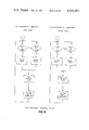
- FIG. 9 contains flow diagrams showing the basic operation of the Data Management Subsystem and the Outline Converter Subsystem.
- FIG. 10 is a flow diagram for the building of data in the Data RAM in the Data Management Subsystem.
- FIG. 11 is a diagram of the layout of data in the Data RAM.
- FIG. 12 is a diagram showing the structure of the outline data in the Data RAM.
- FIG. 13 shows the location of each raster line character outline intersection derived from the encoded data of FIG. 5.
- FIG. 14 is the overall flow chart showing routines for loading the character data into the Data Ram and the "Big New Outline” process for altering the encoded character data to create a smoother outline for a large character.
- FIG. 15 shows an initial portion of the "Big New Outline” process leading to the subprocesses of FIGS. 16 to 18 and particularly the String Explosion process of FIGS. 16 and 17, and the Table Explosion process of FIGS. 16 and 18.
- FIG. 16 shows in detail the process of FIG. 15, leading to the separate processes of FIGS. 17, 18.
- FIG. 17 shows the flow chart for the Table Explosion process.
- FIG. 18 shows the flow chart for the String Explosion process.
- FIG. 19 shows an outline straight line profile smoothed by the Table Explosion process.
- FIG. 20 shows an outline straight line profile smoothed by the String Explosion process.
- FIG. 21 shows the arrangement of straight lines transversing a change through a reference direction in the outline, such as a vertical parallel to an EM square Side Bearing, and signaling a change in the process for determining delta angularity.
- FIG. 22 shows the replacement straight line encoding following an end of profile condition.
- FIG. 1 of the drawings The preferred embodiment of the present invention will now be described with reference to FIG. 1 of the drawings. Identical elements shown in the various figures are labeled with the same reference numerals.
- FIG. 1 The overall system according to the present invention is shown, in block form, in FIG. 1.
- This general system is divided into an Input System which supplies instructions, character information and font data from separate sources 30 and 32, and an Output Data Processing System 34 which drives a Character Imaging System 36.
- the input device 30 may be a paper tape or magnetic tape reader, a separate computer, an input terminal with a keyboard and CRT screen, or a data transmission channel such as a telephone line.
- This input device 30 supplies to the processing system 34 digital data defining the identity, form, size and placement of characters to be typeset.
- identity of characters is intended to mean the name of each particular character chosen, such as upper case “A”, lower case “a”, upper case “B”, numeral "5"; semi-colon ";” and the like. This identity is given by an ASCII or TTS code.
- the term “form” is intended to designate the shape of each character; i.e., the particular font and the amount and direction of slant.
- size is intended to designate the size in both the X direction ("set width") and in the Y direction ("point size”) of each character.
- placement is intended to mean the coordinate (X,Y) position of the character on the page to be typeset.
- the input device 30 designates the X position and Y position of the upper left corner of the "em” square of at least the first character on the page. Subsequent characters are positioned in relation to the immediately preceding character if no placement information is given.
- the input device 30 may also supply page variant information; that is, "global commands” which apply to all or a group of characters on a page. Examples of such commands are “wrong reading”, which effects a left-right mirror image on the page by flipping the X positions of all characters, and "reverse video” which effects a color reversal for an entire page. For example, with reverse video a page may be imaged as white on black, rather than black on white.
- page variant information that is, "global commands” which apply to all or a group of characters on a page. Examples of such commands are “wrong reading”, which effects a left-right mirror image on the page by flipping the X positions of all characters, and “reverse video” which effects a color reversal for an entire page. For example, with reverse video a page may be imaged as white on black, rather than black on white.
- the font storage unit 32 is essentially a floppy disk reader which may be a part of the input device 30. This font storage unit supplies to the Output Data Processing System 34 digital data defining the font of characters previously selected by the input device 30.
- This "second" digital data (as distinquished from the "first" digital data supplied by the input device 30) defines the contour of each character of a font with respect to a normalized encoded set of straight line outline profiles. The straight lines may be defined as shown by first and second coordinates. In particular, this second digital data defines the profiles or black-white boundaries of each character.
- a "profile” is considered to be simply one boundary of a character, it will be seen that any “dark” portion of a character (if the character is dark on a light background) must lie between two profiles (outer boundaries or edges) of the character.
- the "contour" outline or shape of the character is completely defined.
- this second digital data which defines the contour of each character of a font is that the character contours are defined in terms of a normalized set of outlines defined by straight lines.
- the straight lines may be encoded as vectors with coordinates, such as the X-Y coordinates of a Cartesian coordinate set.
- the term "normalized”, as used herein, is intended to mean that the definition of a character in terms of the coordinate set is only related to any given absolute size or to the final size of the character when it is imaged.
- the digital values defining a character outline in this normalized set of coordinates are the values from which the character is scaled, up or down, to the final output resolution. Unless the scale factor just happens to equal 1 (a unique situation), the character will be defined with a different resolution than the final output.
- the output data processing system 34 which will be described in detail hereinbelow is capable of scaling characters in point sizes. Notwithstanding a range of point sizes, the contour of each character is defined only once with respect to the normalized encoding set of coordinates.
- the Output Data Processing System 34 receives the first digital data defining the identity, form, size and placement of characters to be typeset and the second digital data defining the contour of each character of the chosen font and produces third digital data defining the character boundaries intersecting a raster line.
- This third digital data is stored in one or more raster line buffers, also located within the Output Data Processing system, in readiness for the Character Imaging System 36.
- the raster line storage buffer(s) are preferably formed of a plurality of binary memory elements, each storing a single binary digit corresponding to a respective, unique raster point along the raster line.
- the line buffer(s) store sufficient raster (third digital data) for a portion of the raster line extending the width of at least several characters.
- the line buffer(s) preferably store sufficient data to define an entire raster line extending the complete width of the output print medium which may, for example, be at least the size of a conventional typewritten page.
- the information stored in the raster line storage buffer(s) is translated into a raster line image by a Character Imaging System 36 connected to the Output Data Processing System 34.
- This Character Imaging System creates an image on a print medium for the particular raster line defined by the information stored in the raster line storage buffer(s).
- a drive mechanism is also provided in the Character Imaging System for moving the print medium in a direction transverse to the direction of the imaged raster line.
- the Character Imaging System may comprise some means for creating an image for an entire raster line at once.
- the Character Imaging System preferably includes a device, such as a CRT or laser source, for generating a scanning beam and some means, such as beam deflection circuits or a movable mirror, for moving the scanning beam across the print medium in a scan line.
- a device such as a CRT or laser source
- some means such as beam deflection circuits or a movable mirror
- the Output Data Processing System is responsible for computing the horizontal coordinates, on the page to be typeset, at which the laser scanning beam must be turned on or off for each and every raster line on the page. Its computation is based upon the particular raster line which is required (depth down the page); on the particular characters (i.e., identity) which are to be set at that point on the page; and on the form and size as well as the shape of these characters as defined by the Input System 30, 32.
- DMS Data Management Subsystem
- OCS Output Convertor Subsystem
- a Z80A microprocessor is used in the former and an 8 ⁇ 300 (or "SMS 300") microcontroller with a hardwired processor is used in the latter.
- FIG. 2 shows the Output Data Processing System in block form.
- This system receives the first digital data defining the identity, form, size and placement of the characters to be typeset as well as the second digital data defining the contour of each character from a common Input System.
- the Input System operates with a programmed 8080 microcomputer 62 supported by a RAM 64 of suitable size.
- the microcomputer and memory are arranged on a 8080 bus 66 as are two floppy disk read/write units comprising floppy disk controllers 68 and the disks 70 themselves.
- One disk 70 contains the text information or "first" digital data, while the other disk contains the font information or "second” digital data.
- the bus terminates in an IOP80 interface 72 which communicates with an interface 74 in the Output Data Processing System.
- This latter interface is arranged on a Z80A bus 76 as are the Z80A microprocessor 78 and four memory units 80, 82, 84 and 86 of the Data Management Subsystem.
- the memory unit 80 serves to store the program for the Z80A microprocessor 78 and is a workspace for the microprocessor computations.
- the memory 82 stores the second digital data defining the characters of the chosen font. This data is processed and supplied in a convenient form, which will be described in detail below, to two memories 84 and 86 called “Data RAM's".
- the Data RAM's 84 and 86 are "shared" by the Data Management Subsystem and the Output Converter Subsystem. Basically, the Z80A microprocessor supplies data to these RAM's and the 8 ⁇ 300 microcontroller 88 receives and analyzes this data, under control of a program stored in another memory 90, and supplies pertinent data to a hardwired processor 92. This hardwired processor converts the data into the so-called "third" digital data which is stored in three raster line buffers. The information contained in these buffers is then converted into a video control signal by an interface 94 and supplied to the laser recorder in synchronism with the movement of the scanning beam.
- the circuit blocks and their interconnections employed in the Data Management Subsystem are shown in FIG. 3.
- the responsibility of the Data Management Subsystem is to organize and supply data to the memory shared with the Outline Converter Subsystem so as to facilitate rapid processing by the Output Converter Subsystem. More specifically, the Data Management Subsystem executes the following process steps:
- the integrated circuits and interconnections forming the Outline Converter Subsystem are not shown in detail as they do not form part of the present invention. Basically, the responsibility of the Outline Converter Subsystem is to convert the outline or contour data stored in the shared Data RAM into horizontal stroke data for the later recorder. More specifically, the Outline Converter Subsystem executes the following process steps:
- step (e) Read the next outline(s); repeat step (c) until all outlines have been computed at the level on the page being set.
- the second digital data defining the characters of each desired font is stored on the font floppy disk 32.
- This data is of the "outline" type; that is, it defines the contour of each character with respect to a normalized encoded set of coordinates.
- not all the character outline points on the resolution matrix are encoded.
- the general nature of the encoding scheme is described in the above-referenced, commonly-owned U.S. patent application Ser. No. 905,451, filed May 12, 1978, of
- the font data has been structured to correspond to the size of the sectors of the disk.
- Three separate subfiles comprise a font file as illustrated in FIG. 4:
- the font Control File contains all the data which describes the font as an entity, such as a font description, serial number, number of characters, base jump and fixed space data, etc. This file is totally contained in one floppy disk section (125 words).
- the Character Width File contains the width of each character and other character-related data required by the Input System. This file is contained on one or more full sectors, depending upon the number of characters per font.
- the Outline Data File contains the starting coordinates of character outlines, the vectors that define the shape of the outlines, character control words and file size controls. This file is contained on one or more full sectors, depending upon the number of characters and the shape complexity of the characters.
- the appropriate font data is read from the floppy disk by the Input System and transferred to Font RAM 82 by the DMS.
- each curve describes a vertical outline edge with the following components:
- Defining the character consists of listing all the curves which outline the character. They are listed in descending order; that is, the curves that start at the top of the character are listed first and the bottom last.
- DRU Data Resolution Unit
- An extended em square is 576 ⁇ 576 DRU's.
- Position 0.0 is located at the intersection of the left side bearing (LSB) and the top of the extended em square as illustrated in FIG. 5. Therefore, X (left-right) values can be positive (positive is right) or negative (if a character bound extends to the left of the left side bearing (LSB), but Y (up-down) values will always be positive (positive is down).
- Each outline will be defined by 3 or more data words: a Y word, an X word, and one or more outline (vector/control) bytes.
- the format of these data words is shown in FIG. 6.
- the various parts of the coding shown in FIG. 6 are specified below:
- Xn--This data defines the horizontal position of a start point.
- the left side bearing (LSB) is defined as 0.
- L Bit--The L Bit defines the direction of the dx of the first vector. A one defines a left pointing vector, a zero defines right pointing.
- F Bit--The F Bit or "Flare Bit” defines which vector slope will be used by the decoder in extrapolating the character outline in the region of the grid immediately above the line Yn.
- E Bit--The E Bit or "Extrapolation Bit” defines whether extrapolation is or is not used above the start point grid line Yn.
- this byte defines the slope of the vector outline of the character from the start point (Xn Yn), or from the last vector end point. All vectors are sequenced serially in the same sequence that they occur on the character outline.
- this byte defines a control code.
- the specific control is dependent upon the value of dx (in hexadecimal notation) as indicated below:
- 0,3--Defines the vector with a horizontal displacement of 0 DRU's (a vertical vector) and a vertical displacement greater than 30 DRU's.
- the next data byte defines the binary value of the vertical displacement.
- the data byte has a resultant range of vertical displacements of 0 to 255 inclusive, but it is not utilized between 0 and 30 inclusive. (Example: The two bytes 0/3, 2/6 describe a composite vector that goes vertically down 38 DRU's.)
- 0,5--Defines a vector with a horizontal displacement of 1 DRU and a vertical displacement of 120 DRU's.
- 0,E--Defines a rectilinear outline change with a vertical displacement of 1 DRU and a horizontal displacement greater than 255 DRU's.
- the next data byte defines the binary value of the horizontal displacement in excess of 256.
- the two bytes 0/E, 2/6 describe an outline made up of a 1 DRU vertical and a 294 DRU horizontal displacement.
- the Outline Data File resides on the font floppy disk, and stores a memory image of the data that will be loaded into one or more Font RAMs.
- the file occupies one or more sectors on the disk, and accordingly it is modulo 125 words long.
- FIG. 7 illustrates the file structure.
- Items 2a and 2b comprise the RAM memory image, and may not exceed 16,384 bytes.
- Items 3 and 4 may be repeated as required if the total font outline data exceeds 32,768 or 49,152 bytes.
- the data will occupy the Font RAM beginning at address "4000 and may fill through to address "7FFF (where the initial quotation mark (") indicates a hexidecimal number.
- Addresses in the headers will be absolute; addresses in in the CINDEX will be offset absolute ("0000 through "3FFF) with the two MSB's flagging multi-RAM locations.
- This word defines in binary the number of bytes to be loaded into a Font RAM.
- the count does not include the FSIZE word or the ENDFNT word.
- the count for the first Font RAM includes the entire CINDEX and all header and outline data.
- the character index is variable length and consists of a character count (CCOUNT) and a relative addressed index.
- the CCOUNT is one byte defining in binary the number of characters in the font, and therefore it also defines the word length of the index. It will be a number between 1 and 255 inclusive.
- the RAM address location of CCOUNT is "4000.
- the index contains a one word entry for each character in the font. Each entry is the offset absolute address of the YCOUNT byte for the character.
- the two most significant bits of word indicate in binary the RAM that contains the character, where 00 is the RAM that contains the index.
- the 14 least significant bits contain the offset RAM address (the absolute RAM address less "4000) of the YCOUNT byte of the character.
- the first entry in the index is by definition character number 1 and must correspond with the first character width group in the Character Width File. Character numbers proceed sequentially by implication (there are no expressed character numbers or library numbers at any location in the font).
- This word defines the end of all font data and consists of 2 bytes of zeros.
- Zero data is used to fill through to the end of the floppy disk sector that contains the ENDFNT word.
- each RAM contains all of the character digitization data pertaining to each of the characters located within that RAM.
- the X and Y start locations for characters are listed in the Header File; the vectors and control bytes that define the profiles of characters are listed in the Outline File.
- the two files are separated by a zero data byte (ENDHDR).
- FIG. 8 illustrates the file structure of the Header and Outline Data.
- a checksum byte follows the Outline File and immediately precedes the ENDFNT word or the FSIZE word that separates RAMs.
- the Header File consists of a series of character headers, one for each character in the font. There is no space between headers. Each character header contains (in sequence and without space) a YCOUNT byte, a CSIZE word, and one or more start-pair sets of data words (one set for each pair of starts).
- the YCOUNT byte defines in binary the number of YN entries in the header, which is the same as the number of start pairs.
- the length in each character header is ten times the YCOUNT plus 3 bytes.
- the CSIZE word defines in binary the total amount of data space in bytes that the character fills when loaded once into the Data RAM. Accordingly, it is equal to twelve times the YCOUNT plus the length of all the profile strings addresses within the start-pair data sets.
- YN is the Y Data Word and XN is the X Data Word as defined, N must be even, since outlines always start in pairs.
- AN is the absolute address of the initial byte of the profile string of vectors and controls that define each outline shape. Each address will be a number between "4000" and "7FFF. Addresses may be duplicated within the header file in the event that a profile string is shared (the character outline shape is common) for more than one start point. An address may not point to a profile string located in another RAM.
- the YN, XN, and AN Data Words are sequenced as shown in FIG. 8 and listed without space. Each Each successive YN value is equal to or larger than the preceding YN value.
- a one byte checksum verifies each complete RAM; it is formed with all of the data in the Font-RAM except the CHKSUM byte itself.
- the checksum shall be formed by initializing to zero; then, for each byte, the checksum is rotated right one bit (LSB becomes MSB) and the data byte is added to form the new checksum. Overflow on the addition is ignored.
- the final 8 bit checksum is defined as CHKSUM and is entered after the last data byte.
- the Outline Data File will thus contain two profile strings defining the inner and outer boundaries on the left-hand sides of these characters.
- the highest pair of start points in the character header for the "o", “c” and “e”, respectively, may therefore address these two profile strings.
- a single profile string can serve for various characters which are symmetrical. For example, portions of the character “b” may be summetrical with the character “d” and portions of the character “p” may be symmetrical with the character “q”. Such characters may be defined with the same profile strings which are directed by the "L bit” to move in opposite directions.
- the DMS can contain one to eight Font RAMS.
- the system will function with only one Font RAM, provided that one Font RAM size fonts are used.
- Multiple Font RAMS ensure against degradation in throughput speed on pages with font mixing.
- the DMS copies specific character outline data from the Font RAM into the outline file in the Data RAM. If a font change occurs, the DMS will search the table of font numbers loaded. If the font is not already loaded, the DMS will load the new font into the first empty Font RAM(s). If all Font RAMS are in use, the RAM or RAMs least recently used are overwritten with the new font needed.
- the data stored in the font RAM is identical in content and structure to the Outline Data File font data on the Input System floppy disk.
- the DMS maintains two additional tables per font in the program workspace that are used to regulate data transfer from Font RAM to Data RAM: an In-Seg Table and an In-RAM Table. These are described below.
- In-RAM Table is described below.
- This 512 byte table contains the address within the Data RAM where a character header has been stored. The table is ordered in accordance with the character numbers. Each entry is two bytes. A zero entry indicates that the character data has not been loaded.
- each bit corresponds to a character number between 0 and 255 inclusive.
- the address of the bit is computed by:
- a page position is defined by X, Y coordinates in 1/10 pts. This is called a raster resolution unit (RRU).
- RRU raster resolution unit
- the top left hand corner is position 0,0.
- the maximum page size is 11" ⁇ 17". That is 7954 ⁇ 12,292 RRU. Movement in a page can only be from top to bottom.
- YSL Y set level
- a high resolution laser recorder can have its drum drive gear ratio altered so that each step of the stepper motor 58 drives the drum 56 by 1/20th pt., a high resolution RRU (HRRRU). Horizontal (x) resolution is not increased.
- HRRRU high resolution RRU
- the ODS has a chip switch on the DMS (Z80A) microprocessor which is set for this laser recorder.
- the DMS halves the Ys, and the OCS increments the set level on every other raster output.
- a laser recorder with proof page capability would make 2 stepper motor steps between each raster line, effectively doubling the speed of page setting with proof quality.
- the command for proof page will be entered from the Input System.
- the DMS will set the Ys level depending upon whether the laser recorder is a normal or a high resolution unit, and the OCS will accordingly increment the set level by one or two on each raster output.
- the laser recorder will have either an 81/2" or a 11" wide drum 56.
- the ODS has a chip switch on the DMS (Z80A) microprocessor which is set for 81/2" or 11".
- the DMS uses an appropriate page width when page complementing the XPOS value for wrong reading output.
- Any page can be output from any type of laser recorder in right reading or wrong reading (mirror image).
- the DMS page complements the XPOS location of every character, and complements the X position of every outline on each character and the direction that each outline moves.
- Any page can be output white-on-black or black-on-white (reversed normal).
- HWP hardwired processor
- Line rule is similar to reverse video, except that an entire line (white-on-black or black-on-white) of defined length becomes a single solid color. This command permits generation of line rules on the page.
- This specification sets forth the required data and data format to be transmitted between the Input System and the Output Processing system.
- the transmissions are made through the Input System IOP-80 on a handshake basis of a byte serial transfer.
- Table 1 summarizes all the interface transmissions to the ODP System.
- the Output Data Processing System is a page output machine, principally because the laser recorder must expend the time required to expose a full raster even if it only had data for part of a raster. Therefore the throughput of the machine is enhanced significantly by supplying the laser recorder with all of the graphic data needed in each full raster prior to exposing the raster. This requires storing and regrouping random sequence input data into a top down sequence. Due to memory size limitations in the Output Data Processing System, the data must be further packeted into groups defined as "line segments", which is the standard unit of page data to be transmitted by the Input System.
- the Input System stores digital outline fonts on floppy disks in the manner described above.
- the outline data is required in the solution of the raster on-off points, and this data is transmitted by the Input System on a whole font basis (excluding width data, BLJ data, etc.).
- the Input System stores digital outline fonts on floppy disks in the manner described above.
- the outline data is required in the solution of the raster on-off points, and this data is transmitted by the Input System on a whole font basis (excluding width data, BLJ data, etc.).
- periodic data transfers may be made by the input System, if desired. These include programs, error messages, restart and program reset.
- the power-on reset signal may also originate in the Input System.
- Meta-Language notation will be used to describe the syntax of the data requirements. The following notation will be used:
- Terminal--a fixed bit length symbol element e.g.: all page data elements are 16 bit words.
- Non-Terminal--A higher order language element which is composed of one or more terminals and/or one or more non-terminals.
- braces indicate that the enclosed non-terminal(s) may be not used or used as often as desired.
- coded data which describes a page must be packeted into groups defined as "line segments":
- Each page can consist of one or more line segments followed by an end page code.
- a blank page has no line segments.
- the end page code is a terminating code, and no data relating to the page can be accepted after the code. All functional data received prior to the end page code is not carried over into the next page, and must be repeated as needed.
- Each line segment defines a character set, a reverse video set, and/or a line rule set:
- each line segment is the segment number.
- Separate line segments with unique segment numbers must be defined for each character set with a unique YPOS and point size combination.
- Separate line segments should preferably be defined for each reverse video or line rule set, and also preferably for a set that is not contained within the Y limits of the extended em square of a character set. All reverse video or line rule sets within a single line segment must have the same YPOS value.
- the segment number is followed by YPOS, which nominally is the Y coordinate on the page of the top of the extended em square of the characters in the line segment and/or the upper coordinate of the reverse video or line rule set(s) in the line segment. All the line segments on the page must be sequenced in the order of the YPOS coordinate; there is no sequence requirement between line segments with the same YPOS coordinate.
- the line segment can contain one or more character sets, and/or one or more reverse video and/or line rule sets.
- the initial character in a line segment must contain a size, a font number, the x coordinate of the character's left side bearing (XPOS), and the character pair data which is structured:
- the character code is partially a terminating code, that is, although no functions relating to a particular character can be accepted after the code, all functional data received prior to the code is carried over and remains valid until altered by a new function code or a line segment terminating code (END SEG).
- the elements of the reverse video set must be sequenced in the above order with no intervening elements.
- the elements of the line rule set must be sequenced in the above order with no intervening elements.
- Table 2 summarizes the syntax of the page data structure:
- Table 3 summarizes the input code structure for those terminal elements which are to be sent from the Input System to the Output Data Processing System, with references to the following descriptions of the terminal elements used in the syntax the "Page Data Structure".
- Segment numbers may be any number between 1 and 8191 inclusive (not zero), and it is not required that the segment numbers be sequenced with increasing YPOS values.
- the top of the page (which is nominally below the top of the sheet of paper) is defined as 0 RRU's. Up to 14 bits are available to describe YPOS values between 0 and 12,292 RRU's (17 inches).
- the LSB of the YPOS corresponds with the LSB of the input word. This code nominally follows the segment number, and is only issued once within a line segment.
- the left hand edge of the sheet of paper and the page is defined as 0.
- Normal margin offsets are controlled by Input System programs. Up to 14 bits are available to describe XPOS values between 0 and 7 and 7,954 RRU's (11 inches).
- the LSB of XPOS corresponds with the LSB of the input word.
- the Input System derives the value from the font data and the point size that the logo is being set at. If this code is issued more than once, the highest value (lowest point on page) is retained by the Output Data Processing System. Scaling, zero placement, and data placement are identical to YPOS.
- This terminal code defines the font number to be used for all characters following until a new font is input. Up to 10 bits are available to input font numbers between 1 and 254 inclusive.
- the font number LSB corresponds to the word LSB.
- This terminal code defines the point size to be used for all characters in the line segment. It may only be issued once within a line segment. Up to 10 bits are available to input all half point sizes between 1/2 and 130 inclusive.
- the word LSB corresponds to 1/2 point, and bits 1 thru 8 define the binary value of the point size directly.
- This terminal code defines the set width to be used for all characters following until a new set width is input. If this code is not issued, the set width has a default value equal to the point size of the line segment being set. The set width command(s) must follow the point size commands.
- This terminal code defines that the immediately following 2 words represent the YEND and XEND respectively in a line rule set in which YPOS and XPOS preceding are the beginning coordinates.
- the 10 LSB's of the input code are zero.
- This terminal code defines the slant amount to be used for all characters following in the line segment until a new slant is input. Up to 10 bits are available to define 5 possible slant conditions; value 0 corresponds to SLANT OFF, value 1 to SLANT +7, value 2 to SLANT +14, value 3 to SLANT -7, and value 4 to SLANT -14.
- This terminal code defines the end of a line segment, and sets all variable functions contained within that segment to the default value.
- the 10 LSB's are all zero.
- This terminal code defines the end of a page, and sets all variable functions to the default value.
- the 10 LSB's are all zero.
- This code must be preceded by a line segment which contains a YLOW value equal to the depth of the page.
- Each font consists of one set of character outline data for each character contained in the font. Up to 256 characters may be contained in the font, provided that the total contained in one font is less than 15,328 bytes by twice the total number of outlines in the font.
- the end font code is a terminating code, and no data relating to the font can be accepted after this code.
- the character number is identical to the CHAR terminal described in section above and is a number between 0 and 255 inclusive.
- the number of outlines per character is limited to 255.
- Each outline consists of start coordinates, vectors and controls as required to describe one edge of the character:
- Table 4 summarizes the syntax of the font data structure:
- the data RAM serves as an output buffer for the DMS, and an input buffer for the OCS.
- Two such data RAMs are used within the system, each one is 32K bytes long. Both data RAMs are accessible by the DMS and the OCS with the following limitations:
- a processor may select and operate on only one data RAM at a time.
- a processor may not select a data RAM which is selected by the alternate processor.
- the data RAMs are developed by the DMS and passed onto the OCS for processing. Double buffering FIG. 11 is used in building up the data and therefore two such RAMS exist. This permits the DMS to develop the next buffer of data while the OCS is processing the other. In developing this data RAM, the DMS attempts to fill it with as much data as possible. By so doing, it should provide the OCS with enough data to work with to avoid the possibility of phototype setting unit (PTU) slow down.
- PTU phototype setting unit
- the character profile straight lines are arranged within the font RAM shown by the encoded X and Y start points and outline straight line vector profile addresses in the RAM.
- FIGS. 9 and 10 show the manner of entering the font and line data into the Data Ram memory 84 and 86 (FIG. 2).
- the outline contour is defined by straight lines. These straight lines may be encoded as vectors as shown or by other suitable encoding.
- FIGS. 5 and 13 The significance of the X and Y start points and the X and Y coordinate distances (dx, dy) of each vector in the vector profile is shown in FIGS. 5 and 13.
- the vector profile string FIG. 13 is shown starting at Xn, Yn with the first vector of the profile Vn comprising X and Y coordinate distances dx, dy.
- the current raster level is shown as Ysl and the character intersection point is where vector Vn intersects raster level Ysl.
- the method and apparatus of this invention may be used to alter the encoded vector outline profile and replace selected straight lines of that profile with replacement outlines to produce a smoother outline at the selected size.
- Examples of outlines producing discernible irregularies when expanded would be an outline profile as shown in FIG. 19.
- start points and the direction of the vector profile chosen may be altered to any orientation consistent with the principles of this invention and the method and apparatus shown here should not be limited to the character orientation relative to the general vector profile direction shown.
- the start points may be chosen at the left most side of the character with the outline straight line profiles proceeding generally laterally or horizontally, consistent with the generally accepted orientation of Latin characters.
- Outlines appear always in pairs, a pair of outline profiles defining a portion of the character between them. For the sake of explanation, only single outline profiles are shown.
- Each profile contains contiguous straight lines, defined by vector encoding, each vector having a start point and end point.
- an outline vector profile having successive vectors with an angularity difference (delta angularity) greater than 10° may produce an unsuitable outline when that character is imaged at a size in excess of 50 points.
- a predetermined size or standard is chosen for altering the vector outline profile when it is to be imaged beyond that size standard as the encoded vectors defining the character outlines would produce excessive angularity in the outlines and unsuitable character images.
- the character data is transferred from the font ram 82 in FIG. 2 to the Data Ram memory 84, 86. If the character has been previously transferred to the Data Ram as shown on an In Ram index table then the Header data will be copied into the Data Ram at the profile location and the outline vector 3 profile data from the previous entries for that character will be utilized thereby saving Ram space.
- This predetermined size may be an absolute point size or may be an overall dimension of the imaged character or may be a factor of the normalized encoded size, for example 10 times the normalized encoded point size, or any other suitable standard.
- the data management system microprocessor 78 continues to add or transfer character data from the font ram 82 to the data rams 84, 86.
- FIGS. 15 to 18 The method for altering oversize characeters is shown in the FIGS. 15 to 18.
- the amount of space available in the Data Ram must be sufficient for at least an unexpanded font.
- houskeeping loop parameters are established such as the pointers, the character size count, the remaining space available in Ram, the flags for two smoothing passes and the Y count (the number of profile passes).
- the outline Explosion process shown in FIGS. 15 and 16 is then provided according to the principles of the invention to build the expanded outline profile in the work space and create a smoother outline.
- the Header data for the smoothed character is moved from the font ram to the Data Ram and the new outline profiles are moved from the work space to the Data Ram.
- the addresses in the In Ram and In Segment table are adjusted to reflect the proper address for the outline vector profiles as shown in FIG. 12.
- a look-up table of 256 data locations may be used to provide the angularity of each vector relative to a reference angle and to the dx dy vector coordinates.
- the vectors are encoded by start points (for example x1y1, x2y2) and vector profiles (dy, dx11), (dy, dx12), and so on.
- the look-up table relates 256 combinations of dy and dx coordinate distances to a specific angle angle relative to a reference angle.
- a look up table may be chosen as one alternative in determining the delta angularity.
- the outline data words may be vector coordinate distances (dx, dy, values) or control words, as control words may be encoded within the outline vector profile sequence.
- control coding may be a short hand for encoding certain vectors as shown in pages 20-21 and below:
- first identified vector of the outline profile is moved to the work space 80 and its angularity registered.
- the next or second identified vector of that profile proceeding in a direction from the profile start point is moved to the workspace and its angularity registered.
- the angular difference or delta angularity between the first vector and the second vector is then obtained and compared to a standard.
- the identified vectors in the profile string may be replaced with Replacement Vectors or additional vectors in the outline profile further from the profile start point may be examined and tested against the standard and then retained or replaced as necessary to maintain a smooth character outline.
- the profile vector, furthest from the start point of the two compared vectors is replaced with at least two other Replacement Vectors by the Table Explosion process, FIG. 17.
- the delta angularity (angle 101) formed by identified profile vectors are compared to each other and with a standard or reference angle.
- the second vector of each compared pair, that begins from the start point 103 may be replaced.
- the Replacement Vectors and vectors chosen for replacement will depend upon the relationship of the second vector in the string to the first vector and to the reference angle.
- the second vector, from the profile start point 103 is replaced, by a replacement vector selected from a series of four tables.
- the number of tables of Replacement Vectors and the criteria for selecting these tables may change depending upon the angularity of the encoded vectors, the shape of the character outline desired, and the conventions chosen.
- Table 10 provides replacement vectors where the delta angularity is less than 25° and the second vector angularity is closer than the first vector angularity to a reference angle. (Second vector shallower than first vector).
- Table 20 is provided for replacement vectors where the delta angularity is less than 25° and the angularity of the second vector is further than the angularity of the first vector from the reference angle. (Second vector steeper than first vector).
- Table 30 is provided where the delta angularity is greater than 25° and the second vector angularity is closer to than the first vector to the reference angle (Second vector shallower than the first vector).
- Table 40 is provided where the delta angularity is greater than 25° and the second vector angularity is further than the first vector from the reference angle. (Second vector steeper than the first vector).
- the encoding for the identified second vector from the vector profile start point 103 then is replaced with the replacement vector encoding.
- the first vector adjacent to the start point may be replaced by the replacement vector encoding, depending upon the convention chosen to select and replace vectors.
- the microprocessor 78 then removes the encoded data for the second vector in the string from the start point and replaces with an appropriate vector set from tables 10, 20, 30, 40.
- the replacement vector data is inserted immediately following the encoded data for the first of the two identified vectors and consists of a replacement vector and remainder vector.
- the method for determining the remainder vector is shown in FIG. 19.
- the Replacement Vector is subtracted from the replaced vector coordinate distances to obtain the new remainder vector.
- vector 8C is replaced with replacement vector 24 leaving a remainder 68 between the end of the replacement vector and the end point of the identified replaced vector.
- the Remainder vector can be calculated from the coordinates of the replacement vector 24 and the coordinates of the identified replaced vector 8C.
- a second expansion process may be used where the delta angularity is less than 3° or where the delta angularity is less than 5° and greater than 3° and the angularity of one of the vectors of the two identified vectors is greater than 40°. This case most likely appears in an outline profile string and particularly in a long straight line such as one leg of the letter W.
- additional vectors in the outline vector profile string i.e. vectors 3, 4, and on
- the delta angularity is compared to a standard angularity.
- the string explosion process is used and the angularity of each additional vector of the string is compared to the first vector.
- the cumulative X and Y coordinate distances ⁇ X, ⁇ Y are used in computing the replacement vector.
- Each additional vector in the profile string is compared with the first vector of the string for delta angularity and delta angularity is compared to the standard. Where the delta angularity between the first identified vector and each additional vector is within the standard as it was between the first and second vector, no Replacement Vectors are inserted.
- a replacement vector is indicated.
- the slope of the cumulative X and Y coordinate distances ⁇ x, ⁇ y is computed and the replacement vector is selected having the same slope ⁇ x/ ⁇ y from a table.
- the Replacement Vector length is less than the total vector string length as may be represented by the summation of the X and Y coordinate distances, ⁇ x, ⁇ y then the identified outlines may be retained without any outlines replaced.
- a string may be so small that its effect on the imaged character may be negligible and replacement may be unnecessary. Where the string length is greater than a predetermined size, then the vector string may be replaced.
- the line segments are loaded into one of the shared Data Ram memories, 84, 86 by the microprocessor 78.
- the microprocessor 78 scans each line segment for a font call. If the font has not previously been loaded into the font ram, then the microprocessor appropriately loads the required font into the font ram for transfer to the data ram.
- the microprocessor may identify the size of the character required for display and, responsive to a selected size standard for example a size in excess of 50 point, initiate the procedure for smoothing the outline profiles by altering the normalized encoded data base.
- the normalized encoded character data base comprises a plurality of encoded straight lines extending successively along the character outline.
- the straight lines may be encoded as vectors or be encoded by any other suitable technique.
- the method disclosed may be used with any straight line encoded outline.
- the method includes the steps of selecting a character and character size for display, identifying at least two encoded outline straight lines in the profile, comparing the angle between the straight lines to a standard, and replacing the code for at least one of said identified straight lines with the code for at least two replacement straight lines in response to said comparison, with one of said replacement straight lines being continuous with the non-replaced identified encoded outline straight line.
- the result is the non-replaced and the replacement straight lines define a smoother outline profile.
- At least one of the replacement straight lines is encoded in the outline data to be continuous with the non-replaced outline straight lines and to define an angle with the non-replaced straight lines less than the angle between the original two encoded outline straight lines.
- the method smooths the outline profiles and is generally referred to in the following as an Explosion of the outline profiles although it should be understood this refers to the method and an Explosion of the data does not necessarily take place for all outlines under all circumstances.
- one character size may be selected and may serve as a threshold size or standard, defining larger size characters above the standard which m may be exploded and those outlines below the threshold which need not be exploded.
- the method shown as Big New Outline in FIG. 14 is followed. If the character is less than the threshold size, then the New Outline or same Outline Process is followed and the character data is loaded from the font ram into the data ram.
- the character has not been previously transferred to the data ram, and the point size of the character is less than the above-mentioned size standard or threshhold point size, then the font data from the font ram is transferred to the data ram and the Data Ram address references are altered as necessary.
- each character outline contains at least two profiles.
- housekeeping parameters Prior to the initiation of the Explosion routine for smoothing the outline profiles, housekeeping parameters must be established such as pointer values, a Y count register to indicate the number of outline profiles processed, the flags for at least two passes, an indication of the space available in the work space, and the character size count.
- the Header Data is moved from the front ram to the Data Ram and the new encoded profiles are moved from the work space to the Data Ram with addresses adjusted appropriately for the character data entries, as shown in FIG. 12.
- the character data includes a Y data word and an X data word comprising the Header data and as shown in FIG. 8 and an address corresponding to the encoded straight line profile strings defined in terms of dx and dy coordinates.
- the profiles may also contain control data indispersed with the dx and dy vector coordinate data as shown in FIG. 6.
- the control data is indicated by the zero value for the dy portion of the vector/control data byte corresponding to the four most significant pits.
- code 00 indicates the ends of a profile.
- a vector change direction is indicated by the control code 01 to indicate that the vector while proceeding in the generally downward direction with respect to a vertical 95 parallel to a side bearing 99 of FIG. 19 has now changed direction, and crossed over the vertical 95 and is proceeding towards the other side of the em square, see FIG. 5.
- the change of direction is shown with regard to FIG. 19 wherein the vectors proceed in a downward direction and towards the right side bearing 97 of the em until the end of vector C6.
- the profile then crosses over the vertical reference 95 parallel to the left and right side bearings 99, 97 and the profile direction continues downward and towards the left side bearing 99.
- Code 03 indicates a substantially vertical line with dx equal to zero and the value of the dy coordinate equal to the value of the next byte (i.e. FF equal to 255 units).
- control codes may be vector directions expressed as instructions or may be strictly interpreted as controls as shown by the foregoing Table 5.
- a look up table is used to relate a specific number of combinations of dx and dy coordinates to specific angles.
- the specific angles are also related to a reference angle.
- the reference angle may be a horizontal parallel to the character base line and with the table relating the dx and dy coordinate values of each vector to a specific angular value referred to angularity.
- the method is implemented under control of a microprocessor shown as 78.
- the profile data comprising the vector profile defining the outline is loaded into the work space.
- encoded data of the first vector of the profile is loaded into the work space which may be for example a register.
- the outline profile may comprise vectors as shown in FIG. 19 where the profile comprises vectors 2E, 4E, 8C, C6, 01, B5, 36, and 00, indicating the profile end.
- the vector profile data shown in FIG. 19 contains the control code 01 to indicate a change of direction with respect to the vertical 95 and indicating a change in the way the successive identified vectors angularities are compared.
- the string then continues with vectors B5, 36 and 00.
- vector 2E (hexadecimal) for example may mean the X coordinate distances is 14 units and the Y coordinate distance is 2 units.
- the first identified vector in the outline vector profile is moved to the work space which as stated above could be a register.
- the angularity of the first vector is then obtained from the angularity Look Up Table as described.
- the first vector is examined to determine if it is control code as shown in Table 5. If it is not a control code, the four most significant bits are not zero then the method of smoothing is continued.
- a second identified vector angularity, following the first vector for example is moved to the work space which may be for example a second register.
- the first vector would be 2E and a second vector would be 4E.
- the first register would be loaded with the angularity of 2E and the second register would be loaded with the angularity of 4E.
- Each of the registers would have the value of the angularity of vector 2E (E8) and of vector 4E (D2) derived from the Look Up Table.
- the delta angularity is between 5° and 10° (no explosion), or greater than 60°.
- the angularities of two identified outlines are compared to determine the delta angularity. This comparison will indicate either the occurrence of case 1, case 2 or case 3. Where case 1 or 2 is indicated, then the String or Table Explosion process follows accordingly. Once a table or string explosion is indicated, then the successive outlines in the profile are tested for delta angularity and may be compared to the same standard of either case 1 or 2 initiating the respective explosion process.
- delta angularity is between 5° and 10° or greater than 60°
- no explosion is indicated and the angularity value of the second vector 4E is moved to the first register and the angularity of the next successive vector, the third vector shown as 8C, is moved to the second register and the process of computing the delta angularity between identified vectors is repeated.
- the first register is referred to as the "first” because it holds the angularity of the vector closest to the vector profile start point while the second vector register is referred to as second because it holds the angularity of the vector furthest from the profile start point, of the two identified vectors.
- the method may use two passes, the first pass using the data of the outline profile in the font ram and the second pass using the new vector profiles derived from the original profiles and the replacement profile data defining a smoother curve.
- the first vector is defined as the vector closest to the vector profile start point, 103 FIG. 19.
- the angularity E8 of the first vector 2E is loaded into the first register.
- the angularity value D2 of the second vector, 4E is then loaded into the second register.
- the identified and replacement vector encoding, angularity, and delta angularity is shown in Table 5 and expressed hexadecimal notation.
- the angular difference 101 between the profile's first vector 2E and second vector 4E is a delta angularity of 16, less than or within the standard for Case 1 and Case 2 and within Case 3.
- the method according to the Explosion routine of FIG. 16 then moves the angularity value of the second vector 4E to the first vector register and the angularity value A0 of the third vector 8C to the second vector register.
- the delta angularity 105 between the identified two vectors are then compared. As shown in the table, the angularity difference or the delta angularity 105 between vectors 4E and 8C, the second and the third of the vectors in the profile is shown as 32.
- each replacement vector is represented by encoded dx and dy values.
- These replacement vector codes may be substituted for any one of the identified vectors in the vector profiles.
- a single look up table may be used or a plurality of look up tables constrained only by delta angularity or by relative angularity.
- the replacement vector pair 24-68 is used to replace vector 8C, the "second vector” compared with the "first vector” 4E, and having a delta angularity falling within Case 2.
- the replacement vector pair code 24, 68 is derived from one of the Tables 10, 20, 30 or 40, encoded and is placed in data immediately following vector code 4E so that in continues the outline vector profile from the end point of vector 4E, through vector 24, and vector 68 to the end point of replacement vector 8C.
- the replacement vector 24 is stored. While the table may also store a vector replacement pair 24, 68, to save storage space the first replacement vector 24 may be stored in the table and loaded into the work space in place of the second vector 8C.
- the remainder dx and dy coordinate distances between the vector coordinate distances of vector 8C and replacement vector 24 then may be obtained to derive a remainder vector 68 which would then be loaded into the next work space location following the encoded vector 24.
- the profile string would continue from vector 4E, to vector 24, to vector 68, to the beginning of vector C6.
- profile vector C6 which is one of the original vectors in the outline profile string.
- the vector now corresponding to the "first" vector would be vector 68.
- the angularity of vector 68 would then be loaded into the "first” vector register and with the angularity of vector C6 loaded into the "second” register.
- the angularity is then compared and replacement vectors chosen as before.
- the angularity 4B of vector C6 is compared with the angularity 97 of vector 68 (the remainder vector) producing a delta angularity 106 of 4C falling into the standard for Case 2.
- the replacement vectors shown for C6 would be 43 and 83 with the vector 43 being chosen from one of the look-up tables 10-40 and the vector 83 being computed from the remainder between the angularity of vector C6 and vector 43.
- the remainder vector in this case would be vector 83 having an angularity of 32.
- the outline vector profile then passes through the vertical, 95 and proceeds from a direction generally downward and to the right direction to a generally downward and to the left direction.
- control code 01 indicates a direction change and a change in computation; angularity must be added instead of subtracted to determine the delta angularity.
- the use and placement of this code 01 will vary depending on the convention chosen for the encoding direction and for the derivation of the delta angularities.
- the next identified vector B5 in the profile string supercedes the control code and B5 is loaded into the "second" vector register with the angularity value 32 of vector 83 being loaded into the first vector register.
- the delta angularity is now obtained by adding the two angularities 32 and 45 which sums to 97, falling into Case 2 and B5 is replaced by replacement vector 51 and the remainder vector 64 is similarly derived as shown.
- the angularity of the next identified vector 36 loaded into the "second" register, and compared with the angularity of vector 64, in the first register to produce a delta angularity 75, indicating a corresponding replacement by vector 11 and remainder vector 25.
- a Bottom Extrapolation is a separate routine which may be used to terminate all outline profiles.
- the angularity of the last vector is 25.
- the profile which may be 1F, 10 or 12, shown in FIG. 22.
- 1F indicates a dy increment of 1 and the dx increment of 15.
- 11 indicates a dy increment of 1 and the dx increment of one.
- FIG. 19 The effect of the bottom extrapolation in the Table Explosion of FIG. 17 is shown by FIG. 19 in which encoding for vector 12 is added rounding the end of the profile.
- bottom extrapolation routine is shown with regard to the profile of FIG. 19 that should be understood that this bottom extrapolation routine initiated in response to a vector string code at 00 can be used with any outline vector string.
- code 00 is added to the profile.
- a second pass may be initiated using the new vector profile string comprising vectors 2E, 4E, 24, 68, 43, 83, 01, 51, 64, 11, 25, 12 and 00.
- the first vectors compared would be vectors 2E and 4E, and then vectors 4E and 24 and so on.
- a letter outline such as the outline of a W when laid on an encoding grid may not fit exactly on the encoded grid points and the closest encoded grid points may be chosen to represent the vector outline.
- the horizontal axis in FIG. 20 is doubled to more clearly show the differences between the character outline and encoded outline.
- a String Explosion may be used in the profile of FIG. 20 where the delta angularity 119 is less than 3+ or less than 5° with the angularity of the "second" encoded vector A2 being greater than 40°, indicating Case 1.
- the vector outline profile shown contains vectors 61, A2, F3, F3, and F2 with an encoded 00 indicating the end of the vector profile.
- a second pass is not used in the preferred embodiment so the method for smoothing the string outline profile is used only once.
- a set of registers, containing the accumulative EY, EX coordinate distances is established to provide the x and y values cumlatively totaled for the x and y coordinate distances of the identified vector and additional vectors in the string.
- the String Explosion method is a variation of the overall method of smoothing as is the Table Explosion method.
- the first vector register is loaded with the angularity for vector 61 the "first" vector and the second vector register is loaded with the angularity for vector A2, the "second" vector as shown in FIG. 20.
- This step is common to the String Explosion and Table Explosion as shown in FIG. 16, and is used to identify the occurrence of Cases 2 or 3 for the string or Table Explosion process of FIGS. 16 & 17.
- Each of the successive vectors in the profile are then identified as an additional vector and compared to one of the identified vectors and to the angularity standard initiating the String Explosion.
- a string profile starts at point 121 and consists of vectors 61, A2, F3, F3, F2 and the terminating code 00 indicating the end of a profile.
- the angularity of the first vector 61 is moved to the first register and the angularity of the second vector A2 is moved to the second register.
- control codes such as 01, 02, 03 or 00, the routine will jump ahead to select the next vector and move it into the appropriate register.
- the delta angularity between vectors 61 and vector A2 is determined. Where that delta angularity is less than 3° or less than 5° and with an angularity of at least one of the vectors greater than 40°, a String Explosion is indicated.
- the string explosion is shown in greater detail in FIG. 18.
- a set of string pointer registers Sigma X (EX) and Sigma (EY) is established and each of the vector coordinate distances are added to the appropriate pointer register to determine the running profile length.
- the identified vectors in this profile are 61 and A2. As stated their angularity was obtained from a look up table or some other suitable means and compared initiating case 1 or the string explosion, FIG. 16.
- the angularity of the first vector is then compared with the angularity of an additional vector in the profile string, in this case F3.
- the angularity of the additional vector is obtained and the delta angularity between the additional vector and the first vector in the string 61, closest to the profile start point 121 is compared.
- the process is iterrated with each successive additional vector in the profile string F3 and F2 where the delta angularity between each successive additional vector and first vector 61 is within the case 1 standard initiating the string explosion.
- next additional or successive vector is a control vector such as 00 shown in FIG. 20, then the process jumps to the replacement vector process as stated above.
- the process may be arranged so the set of of vectors in the string profile need not be replaced if the profiles are within a length standard such as 4 vectors or 48 delta units.
- the vector string 61, A2, F3, F3, and F2 are five vectors in length, and according to the preferred embodiment, a replacement vector 117 is selected.
- the EX, EY registers initially contain the summed coordinate distances for the second of the identified profile vectors, A2, shown in FIG. 20.
- the Ex, Ey registers are then incremented with the coordinate distances of each additional profile vector.
- the selected replacement vector is then placed within the encoded data to be contiguous with the first vector 61 of the profile string.
- the replacement vector code replaces the encoded data for the second identified vector and each replaced additional vector.
- the replacement vector can be used to replace all profile vectors, the first identified vector as well as successive vectors in the profile string or the first and second identified vectors may be retained and the replacement vector used to replace only additional vectors in the profile strings as may be appropriate.
- the vectors initially compared and initiating the spring or table explosion shown in FIG. 16 are called the identified vectors.
- each of the successive vectors in the profile string, compared with one of the identified vectors for the string explosion is called an additional vector.
- control code 00 indicating the end of the profile may implement a bottom extrapolation routine as explained with regard to the table explosion.
- Any number of suitable techniques may be used to determine if the string length is beyond the standard which would require a replacement vector or small enough so that a replacement vector would be inappropriate.
- the address pointer value for the last most recently used additional vector initiating the replacement vector may be compared with the address pointer value for the first identified vector to determine the number of vectors in the profile string.
- the Ex, Ey registers may be used to compute or determine the data unit length of the vector string.
- a control code encountered in the profile encoded outline data signifies changes in the profile and initiates changes in the process for smoothing the outline profile.
- the next code encountered in the profile are dy dx vector coordinate distances then the method will continue with identified vectors loaded into the registers and the delta angularity obtained. This is indicated as "jump ahead if not" in FIG. 16.
- the delta angularity 122 between straight lines 123 and 125 may be determined by taking the angularity of lines 123 and 125 relative to the reference angle of straight line 127 and subtracting.
- the angularity of straight line 129 may need to be added to the angularity of straight line 125 where the reference changes between straight line 125 and 129. This occurs in the encoding of the profiles in the preferred embodiment when as shown, a profile changes direction relative to a vertical 131 parallel to the left or right side bearing of a character.
- the control 01 then causes a change in the method of determining the delta angularity.
- the control word 02 indicates a single point in the outline encoded data. Where this occurs, the exit routine is used and the single point is replaced with 1F and the point becomes a vector which can be implemented in the shape of an outline.
- the Bottom Exit routine is initiated by the control code 00 at the end of an outline encoded profile.
Abstract
Description
8=Q+R (Quotient integer and Remainder integer)
              TABLE 1
______________________________________
SUMMARY OF INTERFACE TRANSMISSIONS
              INPUTS TO ODP SYSTEM
              FROM INPUT SYSTEM
______________________________________
CONTROL         NEW PAGE READY
TRANSMISSIONS   RESTART REQUEST
8 BIT BYTE      RESET REQUEST
& CTL = 1       PROOF PAGE
                START PROG STORE
                PROG STORE FAULT
DATA            PROGRAM DATA
TRANSMISSIONS   PAGE DATA
16 BITS         FONT DATA
(TWO BYTES)
& CTL = 0
______________________________________
(PAGE)=[(LINE SEG)]"END PAGE"
(LINE SEG)=(SEG#)*(YPOS)*[(CHAR SET)/(RVSET)/LR SET)]"END SEG"
(CHAR SET)=(INITIAL CHAR)[(CHAR PAIR)]
(INITIAL CHAR)=(PT SIZE)*(FONT)(XPOS)(CHAR PAIR)
(CHAR PAIR)=[(FUNCTION)]"CHAR"
(FUNCTION)=(XPOS)/(FONT)/(SET WIDTH)/(SLANT)/(BLJ)/(YLOW)
(RV SET)=(XPOS)(RV CODE)(YEND)(XEND)
(LR SET)=(XPOS)(LR CODE)(YEND)(XEND)
              TABLE 2
______________________________________
PAGE DATA SYNTAX
(PAGE) = [(LINE SEQ)] "END PAGE"
(LINE SEG) = (SEG#)* (YPOS)*[ (CHAR SET)/(RV SET)/
(LR SET)] "END SEG"
(CHAR SET) = (INITIAL CHAR) [(CHAR PAIR)]
(INITIAL CHAR) = (PT SIZE)*(FONT) (XPOS) (CHAR PAIR)
(CHAR PAIR) = [(FUNCTION] "CHAR"
(FUNCTION) = (XPOS)/(FONT)/(SET WIDTH/(SLANT)/
(BLJ)/(YLOW)
(RV SET) = (XPOS) (RV CODE) (YEND) (XEND)
(LR SET) = (XPOS) (LR CODE) (YEND) XEND)
______________________________________
(SEG#)="SEG#"
(YPOS)-"YPOS"
(XPOS)="XPOS"
TABLE 3 ______________________________________ 16 BITINPUT CODE FORMAT 15 14 13 12 11 10 9 8 7 6 5 4 3 2 1SEG# 0 0 YLOW data in RRU's 0 1 YPOS data in RRU's 1 0 XPOS data in RRU's 1 1 0 0 0 0CHAR number 1 1 0 0 0 1FONT number 1 1 0 0 1 0 PT SIZE in 1/2pts 1 1 0 0 1 1 SETWIDTH in ± 1/8pts 1 1 0 1 0 0LR CODE 1 1 0 1 0 1SLANT 1 1 0 1 1 0RV CODE 1 1 0 1 1 1END SEG 1 1 1 0 0 0 END PAGE ______________________________________
(YLOW)="YLOW"
(FONT)="FONT"
(RV CODE)="RV CODE"
(SEG#)(YPOS)(YLOW)"END SEG",
(SEG#)(YPOS)"END SEG",
(FONT)=[(CHAR OUTLINE DATA)]"END FONT"
(CHAR OUTLINE DATA)=(CHAR)(#OUTLINES)[(OUTLINE)],
(OUTLINE)=(YN)(XN)[(VECTORS)/(CONTROLS)],
(CONTROLS)=(END OUTLINE)/(CHANGE DIRECTION)(NO VECTORS)/(LONG VERTICAL)/(SHALLOW HORIZONTAL)
                                  TABLE 4
__________________________________________________________________________
FONT DATA SYNTAX
(FONT)        = [(CHAR OUTLINE DATA)] "END FONT"
(CHAR OUTLINE DATA)
              = (CHAR) (#OUTLINES) [(OUTLINE)]
(OUTLINE)     = (YN) (XN) [(VECTORS)/(CONTROLS)]
(CONTROLS)    = (END OUTLINE)/(CHANGE DIR/
                (NO VECTORS)/(LONG VERTICAL)/
                (SHALLOW HORIZONTAL)
__________________________________________________________________________
TABLE 5 ______________________________________ Vector Replacement String Angularity Angularity Vector ______________________________________2E E8 16 4E 8C ##STR1## 24 C6 ##STR2## 68 43 01 B5 ##STR3## 83 01 51 B6 ##STR4## 64 11 25 1F 00 00 ______________________________________
______________________________________
                           Relative Angular-
                           ity of vector B to
Table No.  Delta Angularity
                           Vector A
______________________________________
10         <25°     shallower
20         <25°     steeper
30         >25°     shallower
40         >25°     steeper
______________________________________
Claims (46)
Priority Applications (1)
| Application Number | Priority Date | Filing Date | Title |
|---|---|---|---|
| US06/175,990 US4331955A (en) | 1980-08-07 | 1980-08-07 | Method and apparatus for smoothing outlines |
Applications Claiming Priority (1)
| Application Number | Priority Date | Filing Date | Title |
|---|---|---|---|
| US06/175,990 US4331955A (en) | 1980-08-07 | 1980-08-07 | Method and apparatus for smoothing outlines |
Publications (1)
| Publication Number | Publication Date |
|---|---|
| US4331955A true US4331955A (en) | 1982-05-25 |
Family
ID=22642502
Family Applications (1)
| Application Number | Title | Priority Date | Filing Date |
|---|---|---|---|
| US06/175,990 Expired - Lifetime US4331955A (en) | 1980-08-07 | 1980-08-07 | Method and apparatus for smoothing outlines |
Country Status (1)
| Country | Link |
|---|---|
| US (1) | US4331955A (en) |
Cited By (45)
| Publication number | Priority date | Publication date | Assignee | Title |
|---|---|---|---|---|
| US4539563A (en) * | 1981-05-11 | 1985-09-03 | Hitachi, Ltd. | Method and apparatus for drawing lines |
| EP0175178A2 (en) * | 1984-09-10 | 1986-03-26 | Linotype Company | Method for generating a set of signals representing a curve |
| EP0175179A2 (en) * | 1984-09-10 | 1986-03-26 | Linotype Company | Method and apparatus for generating a set of signals representing a curve |
| EP0177704A1 (en) * | 1984-08-09 | 1986-04-16 | Kabushiki Kaisha Toshiba | Smoothing device for an image display |
| US4586037A (en) * | 1983-03-07 | 1986-04-29 | Tektronix, Inc. | Raster display smooth line generation |
| EP0191134A2 (en) * | 1984-09-10 | 1986-08-20 | Linotype Company | Method for generating a set of signals representing a curve |
| US4658248A (en) * | 1984-11-01 | 1987-04-14 | Microtel Limited | Method for generating stroke-vector characters for use in a display system |
| US4660028A (en) * | 1984-11-01 | 1987-04-21 | Microtel Limited | Stroke-vector character generator |
| US4672370A (en) * | 1984-11-01 | 1987-06-09 | Microtel Limited | Technique for scaling characters in a stroke-vector display system |
| EP0243659A1 (en) * | 1986-04-30 | 1987-11-04 | Linotype AG | Surface exposure device for exposing text on a recording carrier, and method for this exposing |
| US4748596A (en) * | 1984-12-13 | 1988-05-31 | Kabushika Kaisha Toshiba | Semiconductor memory device with sense amplifiers |
| US4815009A (en) * | 1987-04-21 | 1989-03-21 | Xerox Corporation | Algorithm for filling an image outline |
| EP0323240A2 (en) * | 1987-12-28 | 1989-07-05 | Sharp Kabushiki Kaisha | Character processor provided with dot pattern correcting function |
| EP0357389A2 (en) * | 1988-08-31 | 1990-03-07 | Canon Kabushiki Kaisha | Output device |
| EP0385777A2 (en) * | 1989-03-02 | 1990-09-05 | Seiko Epson Corporation | Apparatus for and method of generating pattern signals for controlling a display and/or a printer |
| EP0389131A1 (en) * | 1989-03-04 | 1990-09-26 | Brother Kogyo Kabushiki Kaisha | Apparatus for converting image outline data into dot data representative of image dots |
| EP0389145A1 (en) * | 1989-03-10 | 1990-09-26 | Seiko Epson Corporation | Apparatus and method for generating pattern data for a display and/or a printer |
| EP0420575A2 (en) * | 1989-09-26 | 1991-04-03 | Canon Kabushiki Kaisha | Printer apparatus |
| US5093870A (en) * | 1988-03-31 | 1992-03-03 | Ricoh Company, Ltd. | Smoothing method and apparatus for smoothing contour of character |
| US5197108A (en) * | 1988-03-31 | 1993-03-23 | Ricoh Company, Ltd. | Smoothing method and apparatus for smoothing contour of character |
| US5365599A (en) * | 1985-10-07 | 1994-11-15 | Canon Kabushiki Kaisha | Method and system of converting delineative pattern |
| US5499332A (en) * | 1990-04-04 | 1996-03-12 | Canon Kabushiki Kaisha | Character processing method and apparatus |
| US5562350A (en) * | 1988-04-18 | 1996-10-08 | Canon Kabushiki Kaisha | Output apparatus that selects a vector font based on character size |
| US5577170A (en) * | 1993-12-23 | 1996-11-19 | Adobe Systems, Incorporated | Generation of typefaces on high resolution output devices |
| US5623584A (en) * | 1991-04-23 | 1997-04-22 | Canon Kabushiki Kaisha | Output method and apparatus |
| US5838298A (en) * | 1987-02-13 | 1998-11-17 | Canon Kabushiki Kaisha | Image processing apparatus and method for smoothing stairway-like portions of a contour line of an image |
| US5878161A (en) * | 1991-12-26 | 1999-03-02 | Canon Kabushiki Kaisha | Image processing using vector data to reduce noise |
| US5929866A (en) * | 1996-01-25 | 1999-07-27 | Adobe Systems, Inc | Adjusting contrast in anti-aliasing |
| US20040212620A1 (en) * | 1999-08-19 | 2004-10-28 | Adobe Systems Incorporated, A Corporation | Device dependent rendering |
| US20040227771A1 (en) * | 2003-05-16 | 2004-11-18 | Arnold R. David | Dynamic selection of anti-aliasing procedures |
| US20040227770A1 (en) * | 2003-05-16 | 2004-11-18 | Dowling Terence S. | Anisotropic anti-aliasing |
| US6937741B1 (en) * | 1999-11-29 | 2005-08-30 | Canon Kabushiki Kaisha | Image processing apparatus and method, and storage medium therefor |
| US20050219247A1 (en) * | 2004-03-31 | 2005-10-06 | Adobe Systems Incorporated, A Delaware Corporation | Edge detection based stroke adjustment |
| US20070030272A1 (en) * | 2004-03-31 | 2007-02-08 | Dowling Terence S | Glyph Outline Adjustment While Rendering |
| US20070057950A1 (en) * | 2005-09-15 | 2007-03-15 | Microsoft Corporation | Size-based font smoothing |
| JP2007517251A (en) * | 2003-12-31 | 2007-06-28 | ノキア コーポレイション | Configuration for font scaling |
| US20070176935A1 (en) * | 2004-03-31 | 2007-08-02 | Adobe Systems Incorporated | Adjusted Stroke Rendering |
| US20070188497A1 (en) * | 2004-03-31 | 2007-08-16 | Dowling Terence S | Glyph Adjustment in High Resolution Raster While Rendering |
| US20070216690A1 (en) * | 2006-03-15 | 2007-09-20 | Fujitsu Limited | Outline font compression method and outline font decompression method |
| US20080068383A1 (en) * | 2006-09-20 | 2008-03-20 | Adobe Systems Incorporated | Rendering and encoding glyphs |
| US7348983B1 (en) * | 2001-06-22 | 2008-03-25 | Intel Corporation | Method and apparatus for text image stretching |
| US7639258B1 (en) | 2004-03-31 | 2009-12-29 | Adobe Systems Incorporated | Winding order test for digital fonts |
| US20100027077A1 (en) * | 2008-07-31 | 2010-02-04 | Shou-Te Wei | Method of Determining Coordinate on Micro Dotmap according to Moving Vector |
| US20160202899A1 (en) * | 2014-03-17 | 2016-07-14 | Kabushiki Kaisha Kawai Gakki Seisakusho | Handwritten music sign recognition device and program |
| CN116612476A (en) * | 2023-07-20 | 2023-08-18 | 合肥图迅电子科技有限公司 | Chip character detection method and device, computer equipment and storage medium |
Citations (4)
| Publication number | Priority date | Publication date | Assignee | Title |
|---|---|---|---|---|
| US3742484A (en) * | 1971-12-28 | 1973-06-26 | Xerox Corp | Character generating apparatus employing bit stream length correction |
| US3996673A (en) * | 1975-05-29 | 1976-12-14 | Mcdonnell Douglas Corporation | Image generating means |
| US4199815A (en) * | 1978-05-12 | 1980-04-22 | Electra Corporation | Typesetter character generating apparatus |
| US4231096A (en) * | 1978-10-10 | 1980-10-28 | Eltra Corporation | Digital typesetter |
-
1980
- 1980-08-07 US US06/175,990 patent/US4331955A/en not_active Expired - Lifetime
Patent Citations (4)
| Publication number | Priority date | Publication date | Assignee | Title |
|---|---|---|---|---|
| US3742484A (en) * | 1971-12-28 | 1973-06-26 | Xerox Corp | Character generating apparatus employing bit stream length correction |
| US3996673A (en) * | 1975-05-29 | 1976-12-14 | Mcdonnell Douglas Corporation | Image generating means |
| US4199815A (en) * | 1978-05-12 | 1980-04-22 | Electra Corporation | Typesetter character generating apparatus |
| US4231096A (en) * | 1978-10-10 | 1980-10-28 | Eltra Corporation | Digital typesetter |
Cited By (71)
| Publication number | Priority date | Publication date | Assignee | Title |
|---|---|---|---|---|
| US4539563A (en) * | 1981-05-11 | 1985-09-03 | Hitachi, Ltd. | Method and apparatus for drawing lines |
| US4586037A (en) * | 1983-03-07 | 1986-04-29 | Tektronix, Inc. | Raster display smooth line generation |
| EP0177704A1 (en) * | 1984-08-09 | 1986-04-16 | Kabushiki Kaisha Toshiba | Smoothing device for an image display |
| EP0175179A3 (en) * | 1984-09-10 | 1987-10-07 | Allied Corporation | Method and apparatus for generating a set of signals representing a curve |
| EP0175178A2 (en) * | 1984-09-10 | 1986-03-26 | Linotype Company | Method for generating a set of signals representing a curve |
| EP0175179A2 (en) * | 1984-09-10 | 1986-03-26 | Linotype Company | Method and apparatus for generating a set of signals representing a curve |
| EP0191134A2 (en) * | 1984-09-10 | 1986-08-20 | Linotype Company | Method for generating a set of signals representing a curve |
| EP0175178A3 (en) * | 1984-09-10 | 1987-10-14 | Allied Corporation | Method and apparatus for generating a set of signals representing a curve |
| EP0191134A3 (en) * | 1984-09-10 | 1987-10-07 | Allied Corporation | Method and apparatus for generating a set of signals representing a curve |
| US4672370A (en) * | 1984-11-01 | 1987-06-09 | Microtel Limited | Technique for scaling characters in a stroke-vector display system |
| US4660028A (en) * | 1984-11-01 | 1987-04-21 | Microtel Limited | Stroke-vector character generator |
| US4658248A (en) * | 1984-11-01 | 1987-04-14 | Microtel Limited | Method for generating stroke-vector characters for use in a display system |
| US4748596A (en) * | 1984-12-13 | 1988-05-31 | Kabushika Kaisha Toshiba | Semiconductor memory device with sense amplifiers |
| US5365599A (en) * | 1985-10-07 | 1994-11-15 | Canon Kabushiki Kaisha | Method and system of converting delineative pattern |
| EP0243659A1 (en) * | 1986-04-30 | 1987-11-04 | Linotype AG | Surface exposure device for exposing text on a recording carrier, and method for this exposing |
| US4821048A (en) * | 1986-04-30 | 1989-04-11 | Linotype Aktiengesellschaft | Area exposure apparatus for exposing an area of text on a recording carrier and method for conducting the area exposure |
| US5838298A (en) * | 1987-02-13 | 1998-11-17 | Canon Kabushiki Kaisha | Image processing apparatus and method for smoothing stairway-like portions of a contour line of an image |
| US4815009A (en) * | 1987-04-21 | 1989-03-21 | Xerox Corporation | Algorithm for filling an image outline |
| EP0323240A3 (en) * | 1987-12-28 | 1990-09-26 | Sharp Kabushiki Kaisha | Character processor provided with dot pattern correcting function |
| EP0323240A2 (en) * | 1987-12-28 | 1989-07-05 | Sharp Kabushiki Kaisha | Character processor provided with dot pattern correcting function |
| US5093870A (en) * | 1988-03-31 | 1992-03-03 | Ricoh Company, Ltd. | Smoothing method and apparatus for smoothing contour of character |
| US5197108A (en) * | 1988-03-31 | 1993-03-23 | Ricoh Company, Ltd. | Smoothing method and apparatus for smoothing contour of character |
| US5562350A (en) * | 1988-04-18 | 1996-10-08 | Canon Kabushiki Kaisha | Output apparatus that selects a vector font based on character size |
| EP0357389A3 (en) * | 1988-08-31 | 1991-03-27 | Canon Kabushiki Kaisha | Output device |
| US6126342A (en) * | 1988-08-31 | 2000-10-03 | Canon Kabushiki Kaisha | Output device capable of high quality output of characters over a large range of sizes |
| EP0357389A2 (en) * | 1988-08-31 | 1990-03-07 | Canon Kabushiki Kaisha | Output device |
| EP0385777A3 (en) * | 1989-03-02 | 1991-06-19 | Seiko Epson Corporation | Apparatus for and method of generating pattern signals for controlling a display and/or a printer |
| EP0385777A2 (en) * | 1989-03-02 | 1990-09-05 | Seiko Epson Corporation | Apparatus for and method of generating pattern signals for controlling a display and/or a printer |
| US5050228A (en) * | 1989-03-04 | 1991-09-17 | Brother Kogyo Kabushiki Kaisha | Apparatus for converting image outline data into dot data representative of image dots |
| EP0389131A1 (en) * | 1989-03-04 | 1990-09-26 | Brother Kogyo Kabushiki Kaisha | Apparatus for converting image outline data into dot data representative of image dots |
| EP0389145A1 (en) * | 1989-03-10 | 1990-09-26 | Seiko Epson Corporation | Apparatus and method for generating pattern data for a display and/or a printer |
| EP0420575B1 (en) * | 1989-09-26 | 1999-06-30 | Canon Kabushiki Kaisha | Printer apparatus |
| EP0420575A2 (en) * | 1989-09-26 | 1991-04-03 | Canon Kabushiki Kaisha | Printer apparatus |
| US5499332A (en) * | 1990-04-04 | 1996-03-12 | Canon Kabushiki Kaisha | Character processing method and apparatus |
| US5623584A (en) * | 1991-04-23 | 1997-04-22 | Canon Kabushiki Kaisha | Output method and apparatus |
| US5878161A (en) * | 1991-12-26 | 1999-03-02 | Canon Kabushiki Kaisha | Image processing using vector data to reduce noise |
| US5577170A (en) * | 1993-12-23 | 1996-11-19 | Adobe Systems, Incorporated | Generation of typefaces on high resolution output devices |
| US5929866A (en) * | 1996-01-25 | 1999-07-27 | Adobe Systems, Inc | Adjusting contrast in anti-aliasing |
| US20040212620A1 (en) * | 1999-08-19 | 2004-10-28 | Adobe Systems Incorporated, A Corporation | Device dependent rendering |
| US7425960B2 (en) | 1999-08-19 | 2008-09-16 | Adobe Systems Incorporated | Device dependent rendering |
| US7646387B2 (en) | 1999-08-19 | 2010-01-12 | Adobe Systems Incorporated | Device dependent rendering |
| US6937741B1 (en) * | 1999-11-29 | 2005-08-30 | Canon Kabushiki Kaisha | Image processing apparatus and method, and storage medium therefor |
| US7348983B1 (en) * | 2001-06-22 | 2008-03-25 | Intel Corporation | Method and apparatus for text image stretching |
| US20040227770A1 (en) * | 2003-05-16 | 2004-11-18 | Dowling Terence S. | Anisotropic anti-aliasing |
| US7006107B2 (en) | 2003-05-16 | 2006-02-28 | Adobe Systems Incorporated | Anisotropic anti-aliasing |
| US7002597B2 (en) | 2003-05-16 | 2006-02-21 | Adobe Systems Incorporated | Dynamic selection of anti-aliasing procedures |
| US20040227771A1 (en) * | 2003-05-16 | 2004-11-18 | Arnold R. David | Dynamic selection of anti-aliasing procedures |
| JP2007517251A (en) * | 2003-12-31 | 2007-06-28 | ノキア コーポレイション | Configuration for font scaling |
| US7639258B1 (en) | 2004-03-31 | 2009-12-29 | Adobe Systems Incorporated | Winding order test for digital fonts |
| US7602390B2 (en) | 2004-03-31 | 2009-10-13 | Adobe Systems Incorporated | Edge detection based stroke adjustment |
| US7719536B2 (en) | 2004-03-31 | 2010-05-18 | Adobe Systems Incorporated | Glyph adjustment in high resolution raster while rendering |
| US7333110B2 (en) | 2004-03-31 | 2008-02-19 | Adobe Systems Incorporated | Adjusted stroke rendering |
| US20050219247A1 (en) * | 2004-03-31 | 2005-10-06 | Adobe Systems Incorporated, A Delaware Corporation | Edge detection based stroke adjustment |
| US20070176935A1 (en) * | 2004-03-31 | 2007-08-02 | Adobe Systems Incorporated | Adjusted Stroke Rendering |
| US20070188497A1 (en) * | 2004-03-31 | 2007-08-16 | Dowling Terence S | Glyph Adjustment in High Resolution Raster While Rendering |
| US7408555B2 (en) | 2004-03-31 | 2008-08-05 | Adobe Systems Incorporated | Adjusted Stroke Rendering |
| US20070030272A1 (en) * | 2004-03-31 | 2007-02-08 | Dowling Terence S | Glyph Outline Adjustment While Rendering |
| US7580039B2 (en) | 2004-03-31 | 2009-08-25 | Adobe Systems Incorporated | Glyph outline adjustment while rendering |
| US7388591B2 (en) * | 2005-09-15 | 2008-06-17 | Microsoft Corporation | Size-based font smoothing |
| US20070057950A1 (en) * | 2005-09-15 | 2007-03-15 | Microsoft Corporation | Size-based font smoothing |
| US20070216690A1 (en) * | 2006-03-15 | 2007-09-20 | Fujitsu Limited | Outline font compression method and outline font decompression method |
| US8866820B2 (en) * | 2006-03-15 | 2014-10-21 | Fujitsu Limited | Outline font compression method and outline font decompression method |
| US20080068383A1 (en) * | 2006-09-20 | 2008-03-20 | Adobe Systems Incorporated | Rendering and encoding glyphs |
| US20100027077A1 (en) * | 2008-07-31 | 2010-02-04 | Shou-Te Wei | Method of Determining Coordinate on Micro Dotmap according to Moving Vector |
| US8513546B2 (en) * | 2008-07-31 | 2013-08-20 | Pixart Imaging Inc. | Method of determining coordinate on micro dotmap according to moving vector |
| US20130301087A1 (en) * | 2008-07-31 | 2013-11-14 | Pixart Imaging Inc. | Method of Determining Coordinate on Micro Dotmap according to Moving Vector |
| US8729411B2 (en) * | 2008-07-31 | 2014-05-20 | Pixart Imaging Inc. | Method of determining coordinate on micro dotmap according to moving vector |
| US20160202899A1 (en) * | 2014-03-17 | 2016-07-14 | Kabushiki Kaisha Kawai Gakki Seisakusho | Handwritten music sign recognition device and program |
| US10725650B2 (en) * | 2014-03-17 | 2020-07-28 | Kabushiki Kaisha Kawai Gakki Seisakusho | Handwritten music sign recognition device and program |
| CN116612476A (en) * | 2023-07-20 | 2023-08-18 | 合肥图迅电子科技有限公司 | Chip character detection method and device, computer equipment and storage medium |
| CN116612476B (en) * | 2023-07-20 | 2023-09-22 | 合肥图迅电子科技有限公司 | Chip character detection method and device, computer equipment and storage medium |
Similar Documents
| Publication | Publication Date | Title |
|---|---|---|
| US4331955A (en) | Method and apparatus for smoothing outlines | |
| US4345245A (en) | Method and apparatus for arranging segmented character groups in a digital typesetter | |
| US4231096A (en) | Digital typesetter | |
| CA1105619A (en) | Character generating method and apparatus | |
| US4298945A (en) | Character generating method and apparatus | |
| US4254468A (en) | Typesetter character generating apparatus | |
| US5386510A (en) | Method of and apparatus for converting outline data to raster data | |
| US4555802A (en) | Compaction and decompaction of non-coded information bearing signals | |
| US5526476A (en) | Method and apparatus for generating character patterns expressed by coordinates of a coordinate system | |
| US4573201A (en) | Data processing method of binary graphic pattern and system therefor | |
| US4655622A (en) | Printer control apparatus | |
| US4712185A (en) | Dot interpolation control system | |
| EP0095536B1 (en) | The representation of character images in a compact form for computer storage | |
| GB1558458A (en) | Raster printing system | |
| US3546681A (en) | Programmed method for manipulating electronic fonts in electronic photocomposition systems | |
| US5537131A (en) | Character generating method and apparatus | |
| GB2115657A (en) | Method of storing characters and photo-typsetting apparatus | |
| US5574842A (en) | Document processing apparatus and method for generating a character or symbol pattern across a plurality of lines | |
| US5542050A (en) | Font information transfer system | |
| JP3034140B2 (en) | Character generation method and device | |
| EP0385269A3 (en) | Apparatus and method for generating character pattern | |
| JP3034141B2 (en) | Character generation method and device | |
| JPH049152B2 (en) | ||
| JPH0661960B2 (en) | Dot interpolation control device | |
| KR900004948B1 (en) | Under/side line pattern generating device |
Legal Events
| Date | Code | Title | Description |
|---|---|---|---|
| AS | Assignment |
Owner name: ELTRA CORPORATION, DELAWARE Free format text: ASSIGNMENT OF ASSIGNORS INTEREST;ASSIGNOR:HANSEN WALTER I.;REEL/FRAME:003794/0258 Effective date: 19800729 Owner name: ELTRA CORPORATION, NEW JERSEY Free format text: ASSIGNMENT OF ASSIGNORS INTEREST;ASSIGNOR:HANSEN WALTER I.;REEL/FRAME:003794/0258 Effective date: 19800729 |
|
| STCF | Information on status: patent grant |
Free format text: PATENTED CASE |
|
| AS | Assignment |
Owner name: ALLIED CORPORATION; COLUMBIA RD. AND PARK AVE., MO Free format text: ASSIGNMENT OF ASSIGNORS INTEREST.;ASSIGNOR:ELTRA CORPORATION;REEL/FRAME:004026/0293 Effective date: 19820531 Owner name: ALLIED CORPORATION, NEW JERSEY Free format text: ASSIGNMENT OF ASSIGNORS INTEREST;ASSIGNOR:ELTRA CORPORATION;REEL/FRAME:004026/0293 Effective date: 19820531 |
|
| AS | Assignment |
Owner name: LINOTYPE COMPANY, 425 OSER AVE., HAUPPAUGE, NY 117 Free format text: ASSIGNMENT OF ASSIGNORS INTEREST.;ASSIGNOR:ALLIED CORPORATION, A CORP. OF DE;REEL/FRAME:004754/0711 Effective date: 19870806 Owner name: LINOTYPE COMPANY, NEW YORK Free format text: ASSIGNMENT OF ASSIGNORS INTEREST;ASSIGNOR:ALLIED CORPORATION;REEL/FRAME:004754/0711 Effective date: 19870806 |