US4329582A - Tandem mass spectrometer with synchronized RF fields - Google Patents
Tandem mass spectrometer with synchronized RF fields Download PDFInfo
- Publication number
- US4329582A US4329582A US06/172,592 US17259280A US4329582A US 4329582 A US4329582 A US 4329582A US 17259280 A US17259280 A US 17259280A US 4329582 A US4329582 A US 4329582A
- Authority
- US
- United States
- Prior art keywords
- rods
- rod
- quadrupole
- sections
- sets
- Prior art date
- Legal status (The legal status is an assumption and is not a legal conclusion. Google has not performed a legal analysis and makes no representation as to the accuracy of the status listed.)
- Expired - Lifetime
Links
Images


Classifications
-
- H—ELECTRICITY
- H01—ELECTRIC ELEMENTS
- H01J—ELECTRIC DISCHARGE TUBES OR DISCHARGE LAMPS
- H01J49/00—Particle spectrometers or separator tubes
- H01J49/26—Mass spectrometers or separator tubes
- H01J49/34—Dynamic spectrometers
- H01J49/42—Stability-of-path spectrometers, e.g. monopole, quadrupole, multipole, farvitrons
- H01J49/4205—Device types
- H01J49/421—Mass filters, i.e. deviating unwanted ions without trapping
- H01J49/4215—Quadrupole mass filters
-
- H—ELECTRICITY
- H01—ELECTRIC ELEMENTS
- H01J—ELECTRIC DISCHARGE TUBES OR DISCHARGE LAMPS
- H01J49/00—Particle spectrometers or separator tubes
- H01J49/004—Combinations of spectrometers, tandem spectrometers, e.g. MS/MS, MSn
- H01J49/0045—Combinations of spectrometers, tandem spectrometers, e.g. MS/MS, MSn characterised by the fragmentation or other specific reaction
- H01J49/005—Combinations of spectrometers, tandem spectrometers, e.g. MS/MS, MSn characterised by the fragmentation or other specific reaction by collision with gas, e.g. by introducing gas or by accelerating ions with an electric field
-
- H—ELECTRICITY
- H01—ELECTRIC ELEMENTS
- H01J—ELECTRIC DISCHARGE TUBES OR DISCHARGE LAMPS
- H01J49/00—Particle spectrometers or separator tubes
- H01J49/02—Details
- H01J49/06—Electron- or ion-optical arrangements
- H01J49/062—Ion guides
- H01J49/063—Multipole ion guides, e.g. quadrupoles, hexapoles
Definitions
- This invention relates to a tandem quadrupole mass spectrometer system.
- a tandem mass spectrometer system may be used to create ion species from a sample, select one individual ion species, fragment that species, and obtain the mass spectrum of the fragments.
- the letter discloses that a quadrupole mass filter, an AC-only quadrupole section, and a second quadrupole mass filter are arranged in series. Gas is introduced into the center quadrupole section to produce collision induced dissociation. Each quadrupole is arranged in its own cylindrical container with end apertures and operates separately. With a system such as this, it is found that ion signal losses are very large as the ions travel from one quadrupole to the next, and therefore the sensitivity of the apparatus is greatly reduced.
- the invention provides a quadrupole mass spectrometer system having a vacuum chamber, first and second sets of elongated rods in said chamber, the rods of each set being spaced laterally apart a short distance from each other to define a longitudinally elongated space between the rods of each set for ions to travel through said space, said first set of rods being located end to end with said second set of rods so that said spaces are linearly aligned so that an ion may travel through both said spaces, the ends of the rods of said first set being located closely longitudinally adjacent the ends of the rods of said second set, the rods of said first set being DC electrically insulated from the rods of said second set, means for applying an AC-only voltage to said rods of said second set, means for applying both AC and DC voltages to the rods
- FIG. 1 is a partly diagrammatic cross sectional view of a mass spectrometer system which may be used with the present invention
- FIG. 2 is a cross sectional view of the apparatus of FIG. 1 taken along lines 2--2 of FIG. 1;
- FIG. 3 is a perspective view, partly in section, showing the rods of one of the mass spectrometers of FIG. 1 mounted in a holder;
- FIG. 4 is an end view showing open structure rods of the mass spectrometer system of FIG. 1;
- FIG. 5 is a side view showing the rods of FIG. 4;
- FIG. 6 is a standard stability diagram for a mass spectrometer
- FIG. 7 is a plot showing diagrammatically the rise and fall of the AC field along the length of the tandem mass spectrometer system of FIG. 1;
- FIG. 8 is a plot showing typical emittance or acceptance elipses for a mass spectrometer
- FIG. 8a is an end view of the rods of a mass spectrometer showing the x and y directions;
- FIG. 9 is a plot showing typical emittance and acceptance elipses for the system of FIG. 1 in the y direction;
- FIG. 10 is a plot showing typical emittance and acceptance elipses for the system of FIG. 1 in the x direction;
- FIG. 11 is a plot showing the travel time of an ion through the system of FIG. 1 expressed in terms of cycles of the applied AC field;
- FIG. 12 is a plot showing the characteristics of a typical ion source
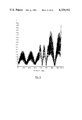
- FIGS. 13 to 29 are plots showing envelope functions for various mass spectrometer systems of the kind shown in FIG. 1;
- FIG. 30 is a block diagram of an electrical control system for use with the mass spectrometer system of FIG. 1.
- FIG. 1 shows a specific mechanical arrangement which may be used to implement the invention.
- the mechanical arrangement shown, with open structure AC-only rods, is as described in the co-pending application of J. B. French filed concurrently herewith.
- FIG. 1 shows a vacuum chamber generally indicated at 2 and which contains three mass spectrometer sections generally indicated at 4, 6, and 8 respectively.
- Spectrometer section 4 is of conventional quadrupole square pattern.
- Spectrometer section 8 is also a conventional quadrupole mass spectrometer and similarly contains four rods 12 arranged in a normal square pattern.
- Spectrometer section 6 also contains four rods 14, arranged as shown in FIG. 3 in normal quadrupole fashion. However the rods 14 have solid center portions, indicated at 14-1, and open structure end extensions, indicated at 14-2.
- the center portions 14-1 of rods 14, and also the rods 10, 12 of quadrupole sections 4, 8 are held in conventional holder plates 16 (FIG. 3).
- the plates 16 of quadrupole sections 4, 8 are located in conventional cylindrical cans or housings 18 (FIGS. 1, 3) which are normally used for mass spectrometers.
- the cans or housings 18 have apertures 20 therein to allow gas within the mass spectrometer sections 4, 8 to be pumped away.
- the center portions 14-1 of rods 14 are however housed in a cylindrical can 22 which is closed except at its ends, which are defined by end discs 24 having apertures 26 therein.
- a duct 28 carries a target gas from a source 29 into the can 22 and into the space between the centre portions 14-1 of rods 14.
- the open structure rod extensions 14-2 of the rods 14 are formed, as shown in FIGS. 4, 5 of thin stiff rods or wires 30.
- Each set of wires 30 is arranged in a curved configuration to simulate the shape of the outer portion of a normal quadrupole rod, so that the field produced by the four sets of wires 30 will correspond as closely as possible to the normal hyperbolic field 31 (FIG. 4) produced by the solid rods of a conventional quadrupole.
- the wires 30 are supported at their inner ends by welds or solder connections to the solid rod portions 14-1. At their outer ends the wires 30 are supported by a holder 32 (see especially FIG.
- the three quadrupole sections 4, 6, 8 are mounted in axial alignment, end to end along the axis of the cylindrical vacuum chamber 2, being held in position by support members not shown.
- Each rod of each of the three sets is aligned axially with each corresponding rod of each other set, so that the spaces between the rods of each set are linearly aligned, for ions to pass therethrough.
- the ends of the rods 10, 12 and 14 are DC insulated from each other by a small air gap or thin layer of insulating material, indicated at 33.
- the end wall of the vacuum chamber 2 contains an aperture 34 through which ions to be examined are supplied from an ion source 36.
- Ion source 36 may typically be the source shown in U.S. Pat. No. 4,148,196, in which a trace gas is admitted to an ionization chamber, ionized, and the resultant ions are drawn by appropriate electric potentials through a curtain gas chamber into the vacuum chamber 2.
- Curtain gas in the curtain gas chamber serves to block entry of unwanted materials into the vacuum chamber 2, and the curtain gas, which may typically be pure nitrogen, also enters the vacuum chamber where it is cryopumped thus permitting maintenance of a high vacuum in the vacuum chamber 2.
- a refrigerating mechanism 38 is provided having an inner tubular finger or cold station 40 and an outer finger or second cold station 42.
- the mechanism 38 is typically able to extract 2-4 watts of thermal energy from the inner finger 40 at 20° K., and is also typically able to extract 5-10 watts of thermal energy from the outer finger 42, at 70° to 90° K.
- a copper support tube 44 is mounted on the top of the inner finger 40, in good thermal contact therewith, and supports at each end a cylindrical shell 46, also made of a good thermal conducting material such as copper.
- the shells 46 have end walls 48 and contain slots (not shown) in their upper surfaces so that the center quadrupole section 6 may be fitted downwardly into the shells 46.
- a pair of intermediate shells 52 are connected to the outer finger 42 and serve to reduce the heat load on the inner shells 46.
- the intermediate shells 52 are mounted on an outer copper support tube 54 concentric with the inner support tube 44, the outer tube 54 being mounted on the second finger 42.
- the exterior surfaces of the intermediate shells 52 are insulated with aluminized plastic film, as indicated at 56, to reduce heat radiation to the intermediate shells 52.
- the outer end walls of the intermediate shells 52 contain inset centre sections 50 spaced by annular gaps 62 from the outer end wall sections 54 and supported thereon by support struts, not shown.
- the gaps 62 assist in cryopumping gas from the end quadrupole sections 4, 8, as will be explained.
- the intermediate shells 52 also contain slots, shown at 64, FIG. 2, in thin upper surfaces to facilitate assembly of the operations.
- ion species from a sample to be considered are supplied from ion source 36 and are focused (by conventional means not shown) to enter the first quadrupole section 4.
- ions of the desired mass are selected and enter the central quadrupole section 6.
- the ions encounter a target gas supplied via duct 28 into the space 68 between the rods 14 of the center quadrupole section.
- the resultant collisions induce dissociation of the ions into fragments or daughter ions, which are then transmitted into the third quadrupole section 8.
- the third quadrupole section 8 acts as a mass filter, selecting the desired fragments or daughter ions for detection by an ion detector 70.
- the end quadrupole sections 4, 8 are supplied with conventional AC and DC voltages, but the center quadrupole section 6, which must pass a wide range of masses, has only an AC voltage applied to its rods 14.
- the gas pressure in the first and third quadrupole sections 4, 8 must be low, typically 10 -5 torr or less for proper quadrupole operation.
- the vacuum chamber 2 is pumped either by being fitted with appropriate cryocooling surfaces, as explained in U.S. Pat. No. 4,148,196, or by vacuum pumps connected to ports 72 in the chamber 2.
- Target gas in the center quadrupole section 6, which tends to enter the space between the rods of the end quadrupole sections 4, 8, is largely pumped away by flowing through the open spaces between the wires 30 and condensing on the cooled surfaces of inner shells 46.
- the advantages of the open structure of the rod extensions 14-2, formed by wires 30, are as follows. Normally in a quadrupole section the gap d1 (FIG. 3) between the rods is relatively small compared with the diameter d2 of the rods (typically d1 may be about one third of d2). Thus if the rods are solid, relatively little gas can escape between them, and therefore a substantial gap must be left between the ends of adjacent quadrupole sections, so that the gas can exit through this gap and so it will not unduly pressurize the cans of the end quadrupole sections 4, 8. For reasons to be explained, large gaps between the quadrupole sections result in substantial ion signal losses.
- the quadrupole sections 4, 6, 8 can be placed very closely adjacent each other, the ends of the rods of each section being separated only by the small gap 33 as discussed. Since a quadrupole section having an AC-only field applied thereto requires less accuracy of manufacture than a quadrupole section having both AC and DC applied to its rods, the open structure described may be used with little or no degradation in performance. Provided that the open sections 14-2 are of reasonably substantial length, only a small proportion of the target gas entering the centre quadrupole section 6 will travel into the end sections 4, 8.
- the parameters of the system may be adjusted so that the gas density in the target region, i.e. in the space between rods 14-1, is in the range between 10 -2 torr and 10 -4 torr, and the lengths of rod extensions 14-2 are each equal to the lengths of rods 14-1 (e.g. 4 inches).
- most of the gas in the target region 68 travels outwardly through the gaps between the wires 30, as indicated by arrows 76, FIG. 5. Only a small proportion of the gas, indicated by arrows 78, is beamed directly into the space between the rods of the end quadrupole sections 4, 8.
- the gas flow entering the spaces between the rods of the end quadrupole sections 4, 8 may be only about 1/200 of the flow through duct 28.
- rods of the centre quadrupole section 6 are shown as having solid centre sections, they can be entirely of open construction, formed by thin wires stretched in tension between end discs spaced apart by support bars, as shown and described in the said copending application of J. B. French.
- the rods of the centre section can be constituted by groups of longitudinally extending wires, using the principles given in a paper published by H. Matsuda and T. Matsuo entitled "A New Method of Producing an Electric Quadrupole Field", published in the International Journal of Mass Spectrometry and In Physics, No. 24, 1977 at page 107.
- a quadrupole field can be produced using a number of wires suitably located, and not necessarily in the same locations as the usual solid rods themselves would assume.
- Such structure can be used and a gas target region created within it, provided that there is minimal interference with gas escaping from the structure.
- the groups of wires which produce a quadrupole field in effect act as rods and the term "rods" in the appended claims refers to any groups of wires or other structure which produces a quadrupole type field.
- FIG. 6 is a standard stability diagram for a quadrupole mass spectrometer.
- FIG. 6 plots "a" against "q", where ##EQU1## and where m is the mass of the ion passing through the spectrometer,
- r o is the radius of the inscribed circle between rods
- w is the angular frequency of the applied AC
- e is the electronic charge.
- a quadrupole mass spectrometer has a high mass cutoff, indicated by line 100, and a low mass cutoff, indicated by line 102.
- the shaded area 104 between the high mass and low mass cutoff lines 100, 102 is a stable region in which an ion trajectory will not touch the rods, i.e. the trajectory is limited in amplitude, i.e. it is non-divergent.
- FIG. 7 shows diagrammatically the three quadrupole sections 4, 6, 8 with the amplitude q of the AC field plotted at 110 beneath them. It will be seen that since the quadrupole sections are close coupled, the field amplitude 110 does not fall to zero and then rise up again between sections; instead the field amplitude in the transition regions 112, 114 between quadrupole sections falls directly from the higher values existing for the sections 4 and 8 to the lower value associated with section 6. Typically the value of q in the sections 4 and 8 will be at or near 0.706, so that the sections 4, 8 operate near the top of the stability diagram, for high selectivity and resolution.
- the value of q in the centre section 6 will be about 0.2, so that when ions are fragmented thereby producing daughter ions of smaller mass, q for the daughter ions will not increase to such a high value as to be outside low mass cutoff line 102 (which would cause the daughter ions not to be transmitted). Since in the transition regions the field does not fall to zero, but instead the operating conditions remain within the stability region, less ion signal is lost.
- FIG. 8 shows the x and y directions and r o for a set of rods 10.
- the x direction is the direction between the positively changed rods 10, assuming that positively charged ions are being analyzed, while the y direction is then the direction between the negatively charged rods 10.
- Ellipses 116, 118 may be either acceptance ellipses, meaning that any ions entering the rod set at a given phase of the AC field with the values of u and u contained within the ellipse will pass through the rod set, or they may be termed emittance ellipses, meaning that any ions having the values of u and u shown in the ellipse at the exit of the rod set, for a given AC phase at the exit of the rod set, have passed through the rod set.
- the emittance and acceptance ellipses are calculated by following the movement of a typical ion, using the fundamental equations of motion for the ion, and integrating them numerically to determine the path of the ion.
- a program for calculating the ellipses is contained in a publication entitled “Quadrupole Mass Spectrometry", edited and partly authored by Peter Dawson, and published in 1976 by Elsevier.
- FIG. 9 shows emittance ellipses for end quadrupole section 4 and acceptance ellipses for the center quadrupole section 6.
- the ellipses drawn are for the y direction, i.e. in the plane extending between the negatively biased rods assuming that the ions under analysis are positively biased.
- the emittance ellipses for the quadrupole section 4 are shown in solid lines at 4y0 to 4y9 for 10 different initial phases of the AC field. The ten phases are 0.1 cycles, i.e. 36°, apart. It will be seen that the axis of the initial ellipse 4y0 is rotated slightly clockwise from the horizontal and that the subsequent ellipses rotate and change in shape as they are rotated.
- the direction of rotation is not uniform and although ellipse 4y2 is rotated counterclockwise from ellipse 4y1, ellipse 4y4 is rotated clockwise from ellipse 4y3.
- Six of the acceptance ellipses for the centre quadrupole section 6, for the y direction are shown in dotted lines in FIG. 9 at 6y0 and 6y5 to 6y9. The remaining four phases are symmetrical with phases 6y8 to 6y9 and are therefore not plotted. It is found that the best overall matching of the emittance and acceptance ellipses, for maximum transmission of ions in the y direction, occurs when the frequencies and phases of the AC fields applied to all of the rod sections 4, 6, 8 are synchronized, with little or no phase shift between adjacent rod sections. The emittance ellipses are then best contained within the acceptance ellipses.
- ellipses 4y0 to 4y9 have been described as emittance ellipses for quadrupole section 4, they can, since the system is symmetrical, also be regarded as acceptance ellipses for the quadrupole section 8, and ellipses 6y0 to 6y9 can be regarded as emittance ellipses for centre quadrupole section 6. Again best matching in the y direction occurs when there is little or no phase shift between the AC voltages applied to the three rod sections, although there will be more losses in ions traveling from section 6 to section 8 since emittance ellipses 6y0 to 6y9 are larger than acceptance ellipses 8y0 to 8y9.
- FIG. 10 shows in solid lines emittance ellipses 4x0 to 4x9 for the end rod section 4 and shows in dotted lines acceptance ellipses 6x0 and 6x5 to 6x9 for the center rod section 6. (The remaining acceptance ellipses for the centre rod section 6 are symmetrical with ellipses 6x6 to 6x9.)
- FIG. 11 explains the interpretation of the envelope function diagrams.
- the envelope E is plotted on the vertical axis and the location of ions as they travel through the three tandem quadrupole spectrometers is plotted on the horizontal axis.
- the horizontal axis is divided into tenths of AC cycles, marked from 0 to 760 (76 cycles).
- the ions from the ion source 36 approach the first rod set 4, assuming a uniform speed for the ions, they pass through an entrance fringing field indicating at 130 and which typically is two cycles in length.
- the ions then travel through the first rod section 4, this process for example occupying 34 cycles, which are indicated at 132.
- the ions then pass through a 2 cycle fringing field 134 to the second rod section 6, where they spend (for example) 15 cycles in the second rod section 6. This period is indicated at 136.
- the ions then pass through another 2 cycle transition region or fringing field 138 to the third rod section 8 where they spend (for example) 19 cycles as indicated at 140.
- the ions then leave the third rod section 8, passing through another two cycle fringing field 142, and travel to the ion detector 70.
- the envelope value E which is plotted along the vertical axis represents the largest displacement of any ion at any time at the location in question, divided by r o .
- the envelope functions are calculated for the x and y directions by determining the trajectories of representative ions according to the techniques used in linear accelerator design, as explained in a book entitled "High Energy Beam Optics" by Claus G. Steffen, a Wiley & Sons publication, with reference particularly to chapter 4 section 5.
- each envelope function is actually ten different curves superimposed on each other. If the value of E exceeds 1, this indicates that some ions are being lost by contact with the rods. Of course even when E exceeds 1, ions entering at some initial phases will be transmitted although ions entering at other initial phases will be lost.
- FIG. 13 Y envelope function
- FIG. 13 illustrates the preferred case where there is zero phase shift between sections 4, 6 and 8.
- E in the Y direction does not exceed 1 and there are theoretically no losses of selected ions in the y direction during transmission through the three quadrupole sections.
- FIG. 14 Y envelope function
- FIG. 14 illustrates the Y envelope function where there is a phase shift of +0.1 cycle (36 degrees) between section 4 and section 6, but no phase shift between sections 6 and 8.
- E remains less than 1 throughout the system and there are theoretically no losses in the Y direction.
- FIG. 15 Y envelope function
- FIG. 15 illustrates the Y envelope function where there is a phase shift of -0.2 cycles (72 degrees) between sections 4 and 6, but no phase shift between sections 6 and 8. It will be seen that E slightly exceeds 1 in the centre section 6 and considerably exceeds 1 in the third section 8 even though there is no phase shift between sections 6 and 8. It will be seen that the phase shift between sections 4 and 6 strongly affects transmission between sections 6 and 8 in the y direction.
- FIG. 16 Y envelope function
- FIG. 16 illustrates the Y envelope function where there is a phase shift of -0.1 cycles (36 degrees) between sections 4 and 6 (i.e. a smaller shift than FIG. 15), and again no shift between sections 6 and 8.
- E is less than 1 in the first and second sections 4, 6 but exceeds 1 in the third section 8, indicating some losses, although not unduly large losses.
- FIG. 17 Y envelope function
- FIG. 17 illustrates the Y envelope function where there is a phase shift of +0.2 cycles (72 degrees) between sections 4 and 6 and no shift between sections 6 and 8. Again E is less than 1 in sections 4 and 6 but slightly exceeds 1 in section 8, indicating slight losses in the Y direction.
- FIG. 18 Y envelope function
- FIG. 18 illustrates the Y envelope function where there is no phase shift between stages 4 and 6 and a -0.1 cycle (-36 degrees) phase shift between stages 6 and 8.
- E is less than 1 until the third stage 8 is reached, where it then exceeds 1, indicating some ion losses.
- FIG. 19 Y envelope function
- FIG. 19 illustrates the Y envelope function where there is a phase shift of -0.05 cycle (-18 degrees) between each section, i.e. between sections 4, 6 and between sections 6, 8. Again E exceeds 1 in the third section 8, indicating some transmission losses.
- FIG. 20 Y envelope function
- FIG. 21 Y envelope function
- FIG. 21 shows the Y envelope function for the same situation as in FIG. 20 but with a phase change of 0.1 cycles (36 degrees) between sections 4 and 6 (no shift between sections 6 and 8). This reduces transmission considerably, as can be seen from the increased value of E. Detailed calculations show a reduction in transmission by a factor of about three as compared with the FIG. 20 case.
- FIG. 22 envelope function
- FIG. 22 shows the Y envelope function for the same situation as in FIG. 20 but with a phase change of only 0.03 cycles (11 degrees) between sections 6 and 8 (no shift between sections 4 and 6).
- E exceeds 1 in the first and third sections 4, 8, but not by as much as in FIG. 20 and detailed calculations show a reduction in transmission from the FIG. 20 situation by about 20 percent.
- FIGS. 23 to 26 show four different x envelope functions, as follows:
- FIG. 23 X envelope function
- the ions take 2 AC cycles to pass through each fringing field region.
- the ions spend 28 cycles in the first section 4, 15 cycles in the second section 6, and 27 cycles in the third section 8.
- FIG. 24 X envelope function
- FIG. 25 X envelope function
- FIG. 26 X envelope function
- FIG. 27 shows an x to y envelope function in which the parameters are the same as for FIG. 23 but the DC for the third section 8 is switched to give an xy combination, and the AC is synchronized in phase for all three section. It will be noted that considerable improvement in ion transmission occurs as compared with FIG. 23.
- FIG. 28 shows an x to y envelope function under the same conditions as for FIG. 27, except that there is a phase shift of -0.1 cycles between the second and third sections 6, 8.
- Detailed calculations show the average ion acceptance to decrease by 35% as compared with FIG. 27.
- FIG. 29 shows a y to x envelope function under the same conditions as for FIG. 27 but with the DC for the third stage 8 switched in the oppositive transverse direction from that of FIG. 27 (still 90 degrees out of phase with FIG. 23).
- the AC is synchronized in phase for all three sections. This results in a considerable improvement in transmission.
- the spacing should not normally exceed r o , the radius of the inscribed circle between the rods. If r o varies for the three sections, the spacing will normally not exceed the smallest r o . It will also be seen that the degree of phase shift in the y direction is important and becomes more important at high resolution. For best transmission in the y direction the phase shift should be below 0.1 cycles and preferably below 0.03 cycles, and typically will be zero or nearly zero.
- phase synchronization in the x direction depends on the operating conditions, and while a phase shift of 0.1 cycles is not always deleterious, full in-phase synchronization usually gives near optimum performance.
- FIG. 30 An electrical circuit for controlling phase relations between the quadrupole sections is shown in block diagram form in FIG. 30.
- an oscillator 180 is provided which produces an AC voltage of the frequency required for mass spectrometer operation (typically 2 to 3 MHz).
- the AC voltage is applied through a buffer amplifier 182 (which prevents feedback) to a power amplifier 184 and to the AC terminals 186 of the first quadrupole section 4.
- DC is supplied by rectifiying a portion of the power amplifier output in a rectifier 188 and applying the resultant DC to the terminals 186.
- Mass selection is controlled by a mass command unit 190, which by varying the output of buffer amplifier 182 controls the level of the AC (and hence also the DC) voltage applied to terminals 186. This changes the operating point of the first quadrupole section 4, in order to select a desired mass for transmission through the rods 10.
- the oscillator 180 is also connected through a phase shifter 192 to another buffer amplifier 194.
- the output of amplifier 192 is connected to another power amplifier 196 which applies AC to the terminals 198 of rods 14 of the centre quadrupole section 6. No DC is applied to the rods 14.
- This arrangement ensures that the AC voltage applied to rods 14 is synchronized in frequency and phase with that applied to rods 10 so that the resultant AC fields are synchronized in frequency and phase.
- the phase shift is preferably zero or nearly zero.
- the oscillator 180 is also connected through a second phase shifter 200 to another buffer amplifier 202.
- the output of buffer amplifier 202 is connected to power amplifier 204 which is connected to the AC terminals 206 of the rods 12 of the third quadrupole section 8.
- DC is again supplied by a rectifier 208, and the level of the voltages applied is controlled by a mass command unit 210 which adjusts the output of buffer amplifier 202.
- phase shifter 200 again ensures that the AC voltage applied to the rods 12 is synchronized in frequency and phase with the AC voltage applied to the rods 10, 14, again so that the AC fields will be synchronized in frequency or phase.
- the phase shift will be zero or nearly zero.
- the DC voltages applied to the rods 10, 12 are normally in phase, but as discussed, the DC voltages applied to the rods can be reversed in some applications.
Abstract
Description
Claims (6)
Priority Applications (1)
| Application Number | Priority Date | Filing Date | Title |
|---|---|---|---|
| US06/172,592 US4329582A (en) | 1980-07-28 | 1980-07-28 | Tandem mass spectrometer with synchronized RF fields |
Applications Claiming Priority (1)
| Application Number | Priority Date | Filing Date | Title |
|---|---|---|---|
| US06/172,592 US4329582A (en) | 1980-07-28 | 1980-07-28 | Tandem mass spectrometer with synchronized RF fields |
Publications (1)
| Publication Number | Publication Date |
|---|---|
| US4329582A true US4329582A (en) | 1982-05-11 |
Family
ID=22628361
Family Applications (1)
| Application Number | Title | Priority Date | Filing Date |
|---|---|---|---|
| US06/172,592 Expired - Lifetime US4329582A (en) | 1980-07-28 | 1980-07-28 | Tandem mass spectrometer with synchronized RF fields |
Country Status (1)
| Country | Link |
|---|---|
| US (1) | US4329582A (en) |
Cited By (15)
| Publication number | Priority date | Publication date | Assignee | Title |
|---|---|---|---|---|
| US5026987A (en) * | 1988-06-02 | 1991-06-25 | Purdue Research Foundation | Mass spectrometer with in-line collision surface means |
| US5089703A (en) * | 1991-05-16 | 1992-02-18 | Finnigan Corporation | Method and apparatus for mass analysis in a multipole mass spectrometer |
| US5521382A (en) * | 1994-02-24 | 1996-05-28 | Shimadzu Corporation | MS/MS type mass analyzer |
| US5998787A (en) * | 1997-10-31 | 1999-12-07 | Mds Inc. | Method of operating a mass spectrometer including a low level resolving DC input to improve signal to noise ratio |
| US6191417B1 (en) | 1998-11-10 | 2001-02-20 | University Of British Columbia | Mass spectrometer including multiple mass analysis stages and method of operation, to give improved resolution |
| US6340814B1 (en) | 1999-07-15 | 2002-01-22 | Sciex, A Division Of Mds Inc. | Mass spectrometer with multiple capacitively coupled mass analysis stages |
| US20020162959A1 (en) * | 2001-05-01 | 2002-11-07 | Shimadzu Corporation | Quadrupole mass spectrometer |
| US6525314B1 (en) * | 1999-09-15 | 2003-02-25 | Waters Investments Limited | Compact high-performance mass spectrometer |
| US6559444B2 (en) | 2000-03-07 | 2003-05-06 | Bruker Daltonik Gmbh | Tandem mass spectrometer comprising only two quadrupole filters |
| US6576897B1 (en) * | 2000-09-13 | 2003-06-10 | Varian, Inc. | Lens-free ion collision cell |
| US20040021072A1 (en) * | 2002-08-05 | 2004-02-05 | Mikhail Soudakov | Geometry for generating a two-dimensional substantially quadrupole field |
| US20040108456A1 (en) * | 2002-08-05 | 2004-06-10 | University Of British Columbia | Axial ejection with improved geometry for generating a two-dimensional substantially quadrupole field |
| US20090032697A1 (en) * | 2007-08-01 | 2009-02-05 | Masuyuki Sugiyama | Mass analyzer and mass analyzing method |
| US20090206275A1 (en) * | 2007-10-03 | 2009-08-20 | Silcon Genesis Corporation | Accelerator particle beam apparatus and method for low contaminate processing |
| JP2015228379A (en) * | 2010-03-02 | 2015-12-17 | サーモ フィニガン リミテッド ライアビリティ カンパニー | Quadrupole mass spectrometer with enhanced sensitivity and mass resolution |
Citations (3)
| Publication number | Priority date | Publication date | Assignee | Title |
|---|---|---|---|---|
| US3147445A (en) * | 1959-11-05 | 1964-09-01 | Thompson Ramo Wooldridge Inc | Quadrupole focusing means for charged particle containment |
| US3473020A (en) * | 1967-06-19 | 1969-10-14 | Bell & Howell Co | Mass analyzer having series aligned curvilinear and rectilinear analyzer sections |
| US4234791A (en) * | 1978-11-13 | 1980-11-18 | Research Corporation | Tandem quadrupole mass spectrometer for selected ion fragmentation studies and low energy collision induced dissociator therefor |
-
1980
- 1980-07-28 US US06/172,592 patent/US4329582A/en not_active Expired - Lifetime
Patent Citations (3)
| Publication number | Priority date | Publication date | Assignee | Title |
|---|---|---|---|---|
| US3147445A (en) * | 1959-11-05 | 1964-09-01 | Thompson Ramo Wooldridge Inc | Quadrupole focusing means for charged particle containment |
| US3473020A (en) * | 1967-06-19 | 1969-10-14 | Bell & Howell Co | Mass analyzer having series aligned curvilinear and rectilinear analyzer sections |
| US4234791A (en) * | 1978-11-13 | 1980-11-18 | Research Corporation | Tandem quadrupole mass spectrometer for selected ion fragmentation studies and low energy collision induced dissociator therefor |
Cited By (19)
| Publication number | Priority date | Publication date | Assignee | Title |
|---|---|---|---|---|
| US5026987A (en) * | 1988-06-02 | 1991-06-25 | Purdue Research Foundation | Mass spectrometer with in-line collision surface means |
| US5089703A (en) * | 1991-05-16 | 1992-02-18 | Finnigan Corporation | Method and apparatus for mass analysis in a multipole mass spectrometer |
| US5521382A (en) * | 1994-02-24 | 1996-05-28 | Shimadzu Corporation | MS/MS type mass analyzer |
| US5998787A (en) * | 1997-10-31 | 1999-12-07 | Mds Inc. | Method of operating a mass spectrometer including a low level resolving DC input to improve signal to noise ratio |
| US6191417B1 (en) | 1998-11-10 | 2001-02-20 | University Of British Columbia | Mass spectrometer including multiple mass analysis stages and method of operation, to give improved resolution |
| US6340814B1 (en) | 1999-07-15 | 2002-01-22 | Sciex, A Division Of Mds Inc. | Mass spectrometer with multiple capacitively coupled mass analysis stages |
| US6525314B1 (en) * | 1999-09-15 | 2003-02-25 | Waters Investments Limited | Compact high-performance mass spectrometer |
| US6559444B2 (en) | 2000-03-07 | 2003-05-06 | Bruker Daltonik Gmbh | Tandem mass spectrometer comprising only two quadrupole filters |
| US6576897B1 (en) * | 2000-09-13 | 2003-06-10 | Varian, Inc. | Lens-free ion collision cell |
| US20020162959A1 (en) * | 2001-05-01 | 2002-11-07 | Shimadzu Corporation | Quadrupole mass spectrometer |
| US6737644B2 (en) * | 2001-05-01 | 2004-05-18 | Shimadzu Corporation | Quadrupole mass spectrometer |
| US20040021072A1 (en) * | 2002-08-05 | 2004-02-05 | Mikhail Soudakov | Geometry for generating a two-dimensional substantially quadrupole field |
| US20040108456A1 (en) * | 2002-08-05 | 2004-06-10 | University Of British Columbia | Axial ejection with improved geometry for generating a two-dimensional substantially quadrupole field |
| US6897438B2 (en) * | 2002-08-05 | 2005-05-24 | University Of British Columbia | Geometry for generating a two-dimensional substantially quadrupole field |
| US7045797B2 (en) | 2002-08-05 | 2006-05-16 | The University Of British Columbia | Axial ejection with improved geometry for generating a two-dimensional substantially quadrupole field |
| US20090032697A1 (en) * | 2007-08-01 | 2009-02-05 | Masuyuki Sugiyama | Mass analyzer and mass analyzing method |
| US8164053B2 (en) * | 2007-08-01 | 2012-04-24 | Hitachi, Ltd. | Mass analyzer and mass analyzing method |
| US20090206275A1 (en) * | 2007-10-03 | 2009-08-20 | Silcon Genesis Corporation | Accelerator particle beam apparatus and method for low contaminate processing |
| JP2015228379A (en) * | 2010-03-02 | 2015-12-17 | サーモ フィニガン リミテッド ライアビリティ カンパニー | Quadrupole mass spectrometer with enhanced sensitivity and mass resolution |
Similar Documents
| Publication | Publication Date | Title |
|---|---|---|
| US4329582A (en) | Tandem mass spectrometer with synchronized RF fields | |
| US4328420A (en) | Tandem mass spectrometer with open structure AC-only rod sections, and method of operating a mass spectrometer system | |
| US8193489B2 (en) | Converging multipole ion guide for ion beam shaping | |
| CA2229070C (en) | Spectrometer with axial field | |
| EP3038134A1 (en) | Multipole ion guides utilizing segmented and helical electrodes, and related systems and methods | |
| US8299421B2 (en) | Low-pressure electron ionization and chemical ionization for mass spectrometry | |
| US9123517B2 (en) | Ion guide with different order multipolar field order distributions across like segments | |
| GB2412491A (en) | Producing a monoenergetic ion beam | |
| EP0490626B1 (en) | Mass spectrometer with electrostatic energy filter | |
| US8362421B2 (en) | Use ion guides with electrodes of small dimensions to concentrate small charged species in a gas at relatively high pressure | |
| US4814613A (en) | Collision cell for triple quadrupole tandem mass spectrometry | |
| US9449804B2 (en) | Dual field multipole converging ion guides, hyperbolic ion guides, and related methods | |
| WO2000063949A1 (en) | Mass spectrometer, including coupling of an atmospheric pressure ion source to a low pressure mass analyzer | |
| US7935922B2 (en) | Ion guide chamber | |
| EP0023826B1 (en) | Tandem quadrupole mass spectrometer system | |
| US5672870A (en) | Mass selective notch filter with quadrupole excision fields | |
| EP0024149B1 (en) | Tandem mass spectrometer and method of operating a mass spectrometer system | |
| US3925662A (en) | High-resolution focussing dipole mass spectrometer | |
| JP3730527B2 (en) | Mass spectrometer | |
| JP2000268770A (en) | Ion guide | |
| US11791149B2 (en) | Axially progressive lens for transporting charged particles | |
| CN213583697U (en) | Prismatic ion guide system | |
| Kankeleit et al. | A velocity separator for heavy ions using radiofrequency deflection | |
| CN111816543A (en) | Prismatic ion guide system | |
| Pau | Trapping and separating polar molecules by a hexapole trap |
Legal Events
| Date | Code | Title | Description |
|---|---|---|---|
| STCF | Information on status: patent grant |
Free format text: PATENTED CASE |
|
| AS | Assignment |
Owner name: MDS HEALTH GROUP LIMITED 30 MERIDIAN ROAD, REXDALE Free format text: ASSIGNMENT OF ASSIGNORS INTEREST.;ASSIGNOR:FRENCH, JOHN B.;REEL/FRAME:004126/0613 Effective date: 19830211 Owner name: CANADIAN PATENTS & DEVELOPMENT LIMITED 275 SLATER Free format text: ASSIGNMENT OF ASSIGNORS INTEREST.;ASSIGNOR:DAWSON, PETER H.;REEL/FRAME:004116/0465 Effective date: 19830211 |
|
| AS | Assignment |
Owner name: MDS HEALTH GROUP LIMITED, 30 MERIDIAN ROAD, REXDAL Free format text: LICENSE;ASSIGNOR:CANADIAN PATENT AND DEVELOPMENT LIMITED;REEL/FRAME:004156/0967 Effective date: 19830628 Owner name: CANADIAN PATENT AND DEVELOPMENT LIMITED, 275 SLATE Free format text: ASSIGNMENT OF ASSIGNORS INTEREST.;ASSIGNOR:MDS HEALTH GROUP LIMITED;REEL/FRAME:004156/0963 Effective date: 19820419 |
|
| AS | Assignment |
Owner name: NATIONAL RESEARCH COUNCIL OF CANADA, CANADA Free format text: ASSIGNMENT OF ASSIGNORS INTEREST.;ASSIGNOR:CANADIAN PATENTS AND DEVELOPMENT LIMITED/SOCIETE CANADIENNE DES BREVETS ET D'EXPLOITATION LIMITEE;REEL/FRAME:006062/0253 Effective date: 19920102 |