US4305646A - Optical system for electro-optical scanner - Google Patents
Optical system for electro-optical scanner Download PDFInfo
- Publication number
- US4305646A US4305646A US06/095,894 US9589479A US4305646A US 4305646 A US4305646 A US 4305646A US 9589479 A US9589479 A US 9589479A US 4305646 A US4305646 A US 4305646A
- Authority
- US
- United States
- Prior art keywords
- light
- scanning
- beams
- locus
- modulator
- Prior art date
- Legal status (The legal status is an assumption and is not a legal conclusion. Google has not performed a legal analysis and makes no representation as to the accuracy of the status listed.)
- Expired - Lifetime
Links
Images


Classifications
-
- B—PERFORMING OPERATIONS; TRANSPORTING
- B41—PRINTING; LINING MACHINES; TYPEWRITERS; STAMPS
- B41J—TYPEWRITERS; SELECTIVE PRINTING MECHANISMS, i.e. MECHANISMS PRINTING OTHERWISE THAN FROM A FORME; CORRECTION OF TYPOGRAPHICAL ERRORS
- B41J2/00—Typewriters or selective printing mechanisms characterised by the printing or marking process for which they are designed
- B41J2/435—Typewriters or selective printing mechanisms characterised by the printing or marking process for which they are designed characterised by selective application of radiation to a printing material or impression-transfer material
- B41J2/47—Typewriters or selective printing mechanisms characterised by the printing or marking process for which they are designed characterised by selective application of radiation to a printing material or impression-transfer material using the combination of scanning and modulation of light
- B41J2/471—Typewriters or selective printing mechanisms characterised by the printing or marking process for which they are designed characterised by selective application of radiation to a printing material or impression-transfer material using the combination of scanning and modulation of light using dot sequential main scanning by means of a light deflector, e.g. a rotating polygonal mirror
-
- B—PERFORMING OPERATIONS; TRANSPORTING
- B41—PRINTING; LINING MACHINES; TYPEWRITERS; STAMPS
- B41B—MACHINES OR ACCESSORIES FOR MAKING, SETTING, OR DISTRIBUTING TYPE; TYPE; PHOTOGRAPHIC OR PHOTOELECTRIC COMPOSING DEVICES
- B41B21/00—Common details of photographic composing machines of the kinds covered in groups B41B17/00 and B41B19/00
- B41B21/16—Optical systems
-
- G—PHYSICS
- G03—PHOTOGRAPHY; CINEMATOGRAPHY; ANALOGOUS TECHNIQUES USING WAVES OTHER THAN OPTICAL WAVES; ELECTROGRAPHY; HOLOGRAPHY
- G03G—ELECTROGRAPHY; ELECTROPHOTOGRAPHY; MAGNETOGRAPHY
- G03G15/00—Apparatus for electrographic processes using a charge pattern
- G03G15/04—Apparatus for electrographic processes using a charge pattern for exposing, i.e. imagewise exposure by optically projecting the original image on a photoconductive recording material
- G03G15/04036—Details of illuminating systems, e.g. lamps, reflectors
- G03G15/04045—Details of illuminating systems, e.g. lamps, reflectors for exposing image information provided otherwise than by directly projecting the original image onto the photoconductive recording material, e.g. digital copiers
- G03G15/04072—Details of illuminating systems, e.g. lamps, reflectors for exposing image information provided otherwise than by directly projecting the original image onto the photoconductive recording material, e.g. digital copiers by laser
-
- G—PHYSICS
- G06—COMPUTING; CALCULATING OR COUNTING
- G06K—GRAPHICAL DATA READING; PRESENTATION OF DATA; RECORD CARRIERS; HANDLING RECORD CARRIERS
- G06K15/00—Arrangements for producing a permanent visual presentation of the output data, e.g. computer output printers
- G06K15/02—Arrangements for producing a permanent visual presentation of the output data, e.g. computer output printers using printers
- G06K15/12—Arrangements for producing a permanent visual presentation of the output data, e.g. computer output printers using printers by photographic printing, e.g. by laser printers
- G06K15/1238—Arrangements for producing a permanent visual presentation of the output data, e.g. computer output printers using printers by photographic printing, e.g. by laser printers simultaneously exposing more than one point
- G06K15/1257—Arrangements for producing a permanent visual presentation of the output data, e.g. computer output printers using printers by photographic printing, e.g. by laser printers simultaneously exposing more than one point on more than one main scanning line
Definitions
- This invention relates to an apparatus for forming images by scanning a light sensitive surface with a modulated light source such as a laser. Its particular utilization is in the printing or typesetting field.
- Hotchkiss Such a system is shown in U.S. Pat. No. 3,984,171 of Hotchkiss.
- the Hotchkiss patent shows a video signal modulating a laser output.
- the modulator is placed in the light path of the laser and may switch the laser beam electro-optically or acoustic-optically in response to digitized video information.
- a beam expander is placed in the light path to expand the diameter of the beam so it may be refocused to a spot size required by the resolution of the system.
- Additional typical components used within the light path are fold mirrors to change the direction of the light path and a spherical compensator to provide the desired straight line or linear continuous scan on the recording medium from the curvilinear scan.
- a scanning mirror is mounted on a motor, such as a galvanometer motor, to drive the mirror and the reflected light beam through an arc.
- a motor such as a galvanometer motor
- the shortened optical path provides a diminished sensitivity to changes in the location of the various components of the optical path due to changes in temperature and other causes, as well as diminishing the sensitivity of any adjustments which may be required by the components and their locations. Additionally, a shortened optical path also enables a smaller, more compact unit to be built, with attendant savings in weight and space.
- a shortened light path requires less sensitive adjustment to convert the curvilinear scan of an oscillating mirror to a distortionless linear scan.
- a shortened light path also reduces light losses and scattering within the system which may reduce the quality of the system output, and minimizes energy required by the system.
- the prior art arrangement of elements within an optical light path has some of the elements arranged independently of all of the other elements, requiring individual adjustment of these independently arranged elements relative to each other. This required a multiple step assembly operation where each of the elements had to be mounted, and then critically aligned with each other so that the optical path was within desired to tolerances. In other cases where some of the elements were aligned with each other by an assembly having a common reference plane, the optical path including the photosensitive material transport was assembled separately from the optical assembly, and required individual adjustment to minimize any out of tolerance condition leading to distortion of the scan at the light sensitive surface.
- This invention relates to the field of matrix printers and display devices wherein characters such as alphanumeric characters are generated by controlling a spot forming device that traverses or scans a copy area. More particularly, this invention relates to a mechanism for controlling the spot forming device as it traverses or scans a scanning path in a raster pattern that covers the area of a page of text.
- An application of this invention may be in a printing system such as an electrophotographic typesetting system wherein type characters are generated by a modulated light spot that scans a fixed linear path on the surface of an electrophotographic material, to selectively discharge areas of the page.
- the modulated light spot, and the raster scan are controlled by a digital processor, which turns the spot forming device on and off in response to character contour data in normalized coordinates in a first digital memory, and input data on the desired locations on a page of the selected characters in a second digital memory.
- a laser beam is used for the light source which is driven through a scanning arc by a scanning means such as an oscillating mirror.
- a light source such as a laser may be used in this device, wherein characters are electronically generated by repeatedly and rapidly scanning a beam of laser light across the image receiving medium. During scanning, the light beam is electronically switched on and off thereby forming a raster line which extends either vertically perpendicular to the line of characters or horizontally parallel to the lines of characters.
- the switching device is preferably a conventional acoustical optical modulator. Light from the modulator is reflected from a scanning mirror which creates a curvilinear scanned beam.
- the output of the laser is a bundle of light rays which may be either larger or smaller than the resolution required by the system.
- the light rays must be focused to a spot compatible with the system resolution.
- a beam expander is placed in the optical path between the modulator and the scanning means.
- the beam expander as in a Kepplerian telescope or a compound microscope, focuses the entering light rays on a first real image area smaller than the area of the ray bundle entering the beam expander. Then, in accordance with known optical techniques, the image at this first real focused area is expanded through the beam expander optics and then refocused on the photosensitive material.
- the resolution, or the minimum spot size on the photosensitive surface is a function of the size of the real imaged area produced in the beam expander, and is directly proportional to the size of the real focused spot produced within the beam expander. To obtain a sufficiently small spot in the system focal plane at the photosensitive image surface, a smaller spot size is required at the above described first real focused area within the beam expander.
- an acoustical optical modulator produces light along two principle axes, a zero order axis and a first order axis.
- the first order axis corresponds to the energized or switched state of the modulator.
- An apertured stop is provided on the principle first order axis. The light of the first order then passes through the aperture, while zero order light is blocked.
- a beam expander is used to focus the light from the laser to the aforesaid first real image spot. This focused spot is then reimaged through the beam expander and refocused onto the imaging surface to a cross-sectional area consistent with the resolution of the system.
- the function of the beam expander is combined with the function of the modulator and with the apertured stop whereby the modulated light is imaged within the beam expander at its internal focal plane, and at a distance where the normally overlapping beams from the modulator have been separated by the optics of the beam expander.
- the beam expander optics separate the overlapping beams, and the apertured stop blocks the undesired beam, at a distance from the modulator where the angularly separated beams otherwise would be overlapping each other.
- the beam expander optics focus one of the beams on a blocking portion of the light stop within the beam expander.
- the apertured stop is placed within the beam expander at a focal plane of the beam expander where each bundle of light rays is imaged to a small focused area and whereby overlapping between the first and zero order light beams is eliminated.
- the use of the apertured stop within the beam expander permits the beams of the zero and first order to be separated at a distance from the modulator output, where they would otherwise be overlapping, and permits the location of the beam expander closer to the output of the modulator.
- the total light path is shortened, providing the advantage of minimizing the adjustments required to bring the light path within the angular tolerances and reducing the amount of adjustment required to minimize distortion within the light path.
- An additional feature of the invention is the use of an optical assembly which provides a plurality of mounting surfaces, referenced to a reference plane. According to the invention, portions of the light path elements, including the scanning mirror, the spherical correcting mirror and any fold mirrors are mounted on a common optical assembly, eliminating the need for any adjustments after the mounting step is completed. Additionally, and according to the principles of this invention, the photosensitive material transport is also mounted on the optical assembly and on its respective surface referenced to a common reference plane so that the optical path from the scanning mirror to the imaging surface on the photosensitive material can be aligned merely be assemblying the components. Any need for further alignment of the imaging surface and transport is eliminated.
- the shortened optical path also provides the capability of minimizing the size of the package, minimizing space and material requirements.
- the laser and modulator may be mounted on a reference machined surface, or, according to the preferred embodiment may be connected together and mounted within diametrically-opposed screw pairs, so both may be adjusted simultaneously relative to the optical path defined by the machined surfaces on the optical assembly.
- the scanning means is a scanning mirror which drives the light beam in a curvilinear path. It is mounted against the shaft of a galvanometer motor, or any other suitable driving device, by means such as a spring clip. This spring clip draws the backside surface of the mirror against the shaft, assuring that the surface of the mirror is in contact with the surface of the shaft and is aligned with the axis of the shaft.
- the system incorporates the features described above in the cross-referenced phototypesetting system applications characterized by the use of a microprocessor driven CRT display for typesetting, composition support, digital font storage, and laser raster recording.
- the system employs electrostatographic printing and produces a rapid and high quality output copy suitable for typesetting.
- the quality of the copy is compared to that produced by metal type. Producing such quality presents difficulties especially where normalized encoded character contour digital data may be greatly "magnified” in forming larger characters. Maintaining suitable quality requires the features disclosed below, are in precise alignment in a minimum space, to produce a substantially distortionless scan.
- the features disclosed and claimed contribute to a high print quality.
- the novel arrangement of the beam expander reduces the length of the optical path, reducing the opportunity for irregularities in the beam, and the alignment means provide more precise alignment of the beam with the imaging surface. These combine to reduce misalignment and degradation of print quality due to vibration, temperature differences, and random unavoidable minor irregularities in optical components, providing print quality equal to that of metal type in a production environment.
- the optical path defining the position of the scanning mirror axis of rotation, the center of curvature of the spherical compensating reflector, and the system focal plane.
- the straight line scan locus is produced at a focal plane perpendicular to the axis of rotation of the scanning device, as well as passing through the center of curvature of the spherical compensating off-axis reflector as explained below.
- FIG. 1 is a perspective view of a keyboard, display terminal, and input and output data systems in accordance with the invention.
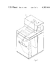
- FIG. 2 is a perspective view of a recorder according to the invention.
- FIG. 3 is a schematic side-elevational view of a recorder according to the invention.
- FIG. 4 is a side-elevational view, partially in section, of a first support structure according to the invention, showing the optical components of a recorder according to the invention.
- FIG. 5 is a fractional view of FIG. 4 taken in direction 5--5.
- FIG. 6 is a fractional front view of FIG. 4 taken in direction 6--6.
- FIG. 7 is a schematic side-elevational view of the mechanism of a recorder according to the invention.
- FIG. 8 is a sectional view of a beam expander according to the invention.
- FIG. 8a is a perspective view of an apertured stop of the device shown in FIG. 7.
- FIG. 9 is a fractional sectional view of the beam expander shown in FIG. 8.
- FIG. 10 is a schematic illustration showing the paths of light beams exiting a modulator according to the invention.
- FIG. 10a is a schematic illustration showing the normal overlap of light beam existing a modulator according to the invention.
- FIG. 10b is a front perspective view of the apertured stop shown in FIG. 7a, illustrating its function in blocking an undesired light beam.
- FIGS. 11, 11a and 11b illustrate the structure for mounting a reflecting mirror to a galvanometer motor shaft according to the invention.
- FIGS. 12, 12a and 12b are elevational views illustrating the formation and use of a spring clip for mounting a reflecting mirror to a galvanometer shaft according to the invention.
- FIG. 13 is a schematic view showing the optical system and light path in the preferred embodiment of the invention, taken in a direction equivalent to the side elevational view of FIG. 4.
- FIG. 13a is a schematic view showing the original system and the light path in the preferred embodiment of the invention, taken as a rear elevational view of the embodiment shown in FIGS. 2 and 3.
- FIGS. 1 and 2 A block diagram of the system is shown in FIGS. 1 and 2, illustrating three subsystems, a keyboard and display terminal, input and output data system, and the recorder system.
- the keyboard display terminal provides data processing facilities for job input, file creation and management, hyphenation and justification, page composition support, outline formating, font management, and typesetting control.
- the input output data system performs font and data processing, raster data conversion, raster line assembly and recorder subsystem control.
- the recorder subsystem is directed by the output data system to generate a modulated raster line, and to control the movement of paper through the loading, processing and unloading of the finished output.
- the output data system for this system is generally described in copending application U.S. Ser. No. 950,242, filed Oct. 10, 1978, and assigned to the common assignee. That application describes an electronic data processing system where a normalized character is stored in memory.
- the processing system receives digital data defining the character identity, form, font size, and placement of the characters to be typeset from the keyboard or from disc or paper storage. It receives second digital data from the font memory defining the contour of each character with respect to a normalized encoding set of first and second coordinates and produces a third set of digital data to define character boundaries intersecting a raster or scan line.
- the third digital data corresponding to the video information, is connected to an acoustical optical modulator for modulating the light directed on the imaging medium along successive raster lines.
- Coordinated drive means are also produced for moving the print medium in a direction transverse to the direction of the raster scan line.
- the second digital data defining the contour of each character comprises digital numbers defining X and Y coordinates of the start points of character outlines and digital numbers defining the length and direction of a plurality of straight line vectors extending successively along the character outline, from the start points.
- the length and direction of each vector is represented by the first coordinate distance dx and the second coordinate distance dy from one end of the vector to the other.
- the digital numbers defining the vectors are arranged such that the vectors comprising an entire string are successively defined before defining the vectors of another string. Further details are provided in the copending patent applications and are, therefore, not provided in this description.
- a keyboard 3 capable of inputting to the processing system digital data defining the identity, form, size, and placement of characters to be printed. Any other suitable input device such as paper tape, magnetic tape, disc readers, a computer, or a data transmission channel may be used.
- a floppy disc drive 5 may be provided in the system with one disc, for example, the disc of drive 7 containing the digital data corresponding to the first digital data, while the disc of drive 9 may contain the digital data corresponding to the font information or second digital data.
- a microcomputer control unit and memory space are contained with the input data subsystem 11.
- the output data processing system for computing the points on each raster line, at which the laser scanning beam must be turned off and on, is contained in the output data processing subsystem 13.
- a CRT soft display 15 is shown mounted on top of the keyboard display console.
- the microprocessor control unit located in the input data subsystem 11 may be used, for example, to display the information placed into the system by means of the keyboard terminal 3 on CRT 15.
- the recorder console is shown in FIG. 2 and In a schematic view in FIG. 3. As shown in FIG. 2, the recorder console is indicated generally by numeral 17 having an optical support subassembly 19, and a copy material transport 21 described in greater detail in the following. A copy delivery slot 23 is provided for receiving the dry finished output of the recorder.
- FIG. 3 shows the schematic diagram of the recorder console which is substantially as described in U.S. Ser. No. 37,698, filed Oct. 10, 1978 and assigned to the common assignee.
- This recorder apparatus comprises a frame 32 on which are mounted the paper transport 34 and the optical support assembly 36, as well as power supplies 38.
- the image receiving medium web 40 is supplied from a replaceable web roll 42 and passed through a pair of feed rollers 44 and 46.
- the upper feed roller 44 is normally spring biased downward against the lower feed roller 46 but may be released by pressing a lever 48.
- the lower feed roller 46 may be driven by a motor (not shown) to move the web 40 forward.
- the web 40 is passed to a cutter 52 which cuts the web into sheets approximately 19 inches (49 cm.) in length. These sheets are wrapped around a rotatable drum 54, 21 inches (53 cm.) in circumference in the preferred embodiment and held in place by vacuum applied through apertures in the outer surface of the drum and as shown in the aforementioned copending application.
- the drum is driven at the desired speed by a motor 56 acting through a work gear 58.
- a corotron 60 Surrounding the drum in a clockwise direction are a corotron 60, an exposing system comprising mirrors 61 and 62, a prewetting device 64, a developing device 66 and a drying device 68. After drying the paper sheet is passed through a chute 70 and deposited in a "basket" 72.
- the exposing system shown in greater detail in FIGS. 3-9, repeatedly and rapidly scans a beam of light across the width of the paper web 40.
- the light beam is generated by a laser 74 and is switched in response to an electronic control signal by a modulator 76.
- the modulator may be an acoustical optical modulator or any other suitable modulation device.
- the beam is then passed through a beam expander shown as the beam expander 78, and is reflected from a scanning device 80 driven through a scanning arc by drive 82. Thereafter, the beam is reflected from a spherical mirror 61 which serves as a field flattener. Finally, the beam is folded and reflected into the horizontal plane by a stationary plane mirror 62.
- the prewetting device 64 is replenished with liquid dispersants from a bottle 84, and the developing device is replenished with toner concentrates from a bottle 86.
- Finger 88 is provided adjacent the drying device 68 to remove the leading edge of the paper sheet from the drum 54.
- a vacuum pump 90 connected to draw air from the interior of the drum 54.
- a blower 92 is connected to supply air to the drying device 68.
- a toner recirculating pump 94 and a reservoir 96 are operative to pass liquid toner to, and receive toner from the developing device 66.
- FIG. 4 the optical support assembly is shown in detail in a partial cross-sectional view and to FIG. 5 where a view of the optical assembly along sectional lines 5--5 is shown.
- the casting 98 contains a cavity area 100 for locating the optical components.
- a laser 74 mounted in the cavity are a laser 74 supported at two separated locations 102-102' and 104-104' by diametrically opposed set screws, it being understood that 90° from the location of each opposed set screw pair are a second diametrically opposed pair so that the laser may be adjusted in two axes.
- a modulator 76 (shown in phantom) is integrally connected to the laser 74 but may be similarly supported by pairs of diametrically opposed screws (not shown). In the preferred embodiment of the invention, adjustment of the opposed set screws is the only adjustment made at assembly. The very small adjustment to align the output of modulator 76 with the optical axis can be accomplished more readily in this manner.
- a beam expander 78 is located with its input optical port 106 facing the output optical port of modulator 76.
- the beam expander 78 may be supported in a manner similar to the laser by opposed screw pairs 108-108' and pairs 110-110', as well as respective 90° displaced pairs (not shown).
- modulator 76 is attached directly to the output port of laser 74. This allows adjustment of the position of laser 74 to also align the first order beam from modulator 76 with the optical axis of the system, reducing the number of adjustments needed in manufacture of a device in accordance with the invention, since beam expander 78 may then be easily and conveniently aligned with the first order beam.
- a conventional, commercially available modulator 76 has an integral angular adjustment, but for adjusting an internal element so that the condition for "Bragg Angle" diffraction is satisfied, and not for alignment of the first order beam path with the optical axis. This positioning of the modulator also yields more efficient modulation, since efficiency of an acoustic optical modulator decreases as area used increases.
- the casting 98 additionally includes machined surfaces for location of certain optical components such as a spherical off-axis mirror, a scanning mirror, a fold mirror, and the paper transport. All surfaces are referenced to common surface 144.
- Surface 116 is a second reference surface perpendicular to surface 144.
- Surfaces 112, 114 are machined parallel to surface 116.
- a center line passing through the axes of dowels 144a and 144b, of the same diameter, is parallel to surface 116.
- Surfaces parallel to surface 144 are machined surfaces 118, 120, 122 and 124.
- Dowels 144a and 144b cooperate with a machined surface on step 144d on transport 21, to vertically locate the transport 21 relative to the casting 98.
- Dowel 144c cooperates with a machined surface, not shown, to laterally locate the transport 21.
- Surface 144 provides a mounting surface for the transport 21. The transport is then aligned in three alignment planes relative to the optical path.
- the reflecting surface face 126 of the diagonal fold mirror 62 can be seen in FIGS. 4 and 6.
- a set of clips shown as clips 128 are provided at each end of the diagonal mirror 62 for simultaneously holding the diagonal mirror 62 in place against machined surfaces 114 and 122.
- a set of springs 130 are shown for holding the spherical mirror 61 against reference machined surface 116.
- a set of clips shown as clips 136, mounted to the face 134 of casting 98 provides additional support for the fold mirror 62.
- a scanning means shown as rotating mirror 138 in FIG. 7 is shown mounted on a shaft 140.
- the shaft is in turn attached to a drive means, such as a galvanometer drive 82.
- the galvanometer drive 82 is mounted on machined surfaces 118 and 120 by suitable mounting means attached to the galvanometer drive 82. These mounting means are shown in greater detail in FIGS. 5, 11, 11a, and 11b.
- the optical path is from the laser 74, through the modulator 76, through beam expander 78, to the scanning mirror 138.
- the galvanometer drive 82 reciprocates scanning mirror 138 through a curvilinear path and causes the light from the modulator to scan across the spherical compensating mirror 61 in an arc corresponding to the arc 142 shown on the spherical compensating mirror surface in FIG. 6.
- the light is then reflected to the face 126 of the fold mirror 62, and out of the plane of FIG. 6, to the paper transport.
- FIG. 5 shows a detail view of the configuration of mounting surfaces 118 and 120.
- a machined mounting surface 118 is provided with apertures 118a and 118b.
- a machined mounting surface 120 is provided with apertures 120a and 120b.
- An aperture 119 is provided in casting 98.
- bolts are passed through apertures 118a, 118b, 120a and 120b to retain a machined surface of galvanometer drive 82 against surfaces 118 and 120.
- Shaft 140, carrying mirror 138 is passed through aperture 119.
- this optical assembly provides reference planes for mounting the optical components for reflecting the light towards the paper transport, as well as reference planes for mounting the paper transport itself. In this way, all of the optical components are automatically placed in alignment with each other upon assembly.
- shims are used as necessary where compensation must be added to maintain the optical portion of the system in alignment.
- such shims are not required, due to precise machining of the reference surfaces, the shortness of the optical path, and other features described herein. This is a significant advantage of the invention allowing full replacement of optical elements and the image surface transport without realignment.
- pads 144 For the purpose of mounting the image of paper transport, a set of machined pads are shown as pads 144 on the face 134 of casting 98. Located within each pad 144 is a threaded mounting hole 146 which may be used for attaching the paper transport. Other appropriate mounting means may be used.
- FIG. 7 The assembly of the paper transport on the optical assembly casting 98 is shown in FIG. 7.
- the mounting pads 144 are referenced to the other and to mounting surfaces 114, 116, 118, 120, 122, and 124.
- FIG. 6 four of the mounting surface pads 144 are shown, it being understood the other mounting surface pads may be added to the assembly casting 98.
- the rotatable drum 54 is shown within the optical path as shown by the arrow from the fold mirror 62 shown in phantom.
- the scanning mirror drive unit 82 is arranged at the top of the optical assembly casting 98 with shaft 140 and reflective surface of mirror 138 shown in phantom.
- a partial light path is shown from the beam expander to the scanning mirror 138 to the spherical compensating mirror 61, to the fold mirror 62 and to the rotating drum 54 where it is imaged on the light sensitive surface of web 40.
- FIG. 8 shows the beam expander 78 in cross-section.
- the beam expander designated by numeral 78 includes a case 148 enclosing a compound lens section 150, 152 for expanding the beam and focusing the beam on the light sensitive surface at focal point 154.
- a lens 156 is provided at the entrance port of the expander opposite the modulator 76.
- the modulator 76 has two states, an energized state and an unenergized state.
- the outputs of the modulator are light beams arranged as a first order beam 158 and a zero order beam 160.
- a majority of its light output will be directed from the modulator in its first order beam 158 and along the principle axis of the beam expander 78, and the remainder will pass undisturbed through modulator 76, in zero order beam 160.
- light In its nonenergized state, light will be directed entirely in the zero order beam 160.
- a spacer 162 is provided to hold an apertured stop 164 having an aperture shown as 166.
- first order light from the modulator is focused and imaged at the location of aperture 166 and is reimaged by lenses 150 and 152.
- the real image at aperture 166 being at the focal point of lens 156, is then expanded and refocused through the compound lens 150 and 152 to focal point 154, corresponding to a spot on the scanned surface of the light sensitive imaging material.
- the compound lenses focus the diverging beam at point 154. It should be understood that the off-axis spherical compensating mirror, the fold mirror and scanning mirrors are interposed between focal point 154 and lenses 150 and 152, but are not shown in FIG. 8, for clarity of illustration.
- the surface 168 of the apertured stop 164 shown in FIG. 8 is a light absorbing material and may be a black mat nonreflective finish or other suitable nonreflecting surface.
- a beam of light entering the lens 156 off the principal axis of beam expander 78 is focused at point 170, removed from the aperture 166 on the black nonreflective, light absorbing surface 168 of the apertured light stop 164.
- the stop 164 blocks the zero order beam, while the first order beam passes through aperture 166.
- the beam expander is aligned along the first order principal axis 174 of the modulator output, as shown in FIGS. 9 and 10.
- the output characteristic of the modulator is as shown in FIGS. 9, 10 and 10a. Up to a distance X from the output of the modulator, the zero order beam 160 and the first order beam 158 are overlapping. At distance X, as shown by FIG. 10a, the two beams contact each other at the point of tangency 172. For any location between X and the modulator output, the beams are overlapping, shown as location X/T in FIG. 10a.
- the free beam light rays along principal axis 176 and principal axis 174 are not separated from each other until a distance X from the output of the modulator.
- the free beam path as shown is without any optical elements.
- a conventional optical stop cannot be used to prevent beam 160 from passing through without blocking part of beam 158. It can be seen, therefore, that a conventional optical stop, permitting the light from beam 158 to pass without permitting any of beam 160 to pass or vice-versa, must be placed at least a distance X from the output of the modulator 76, where the beams are no longer overlapping. This would be at a distance greater than distance X where the beams were sufficiently separate due to the length of the beam and the small, approximately 7.4 milliradian angle between the beams from the zero and first order axes.
- the aperture stop may be moved closer to the output of the modulator, locating it within the distance X where the first and second order free beam paths from the modulator would otherwise be overlapping.
- FIGS. 8 through 10b the combined effect of the beam expander optics is to separate and select first and zero order beams otherwise overlapping each other as shown.
- the modulator provides coherent beams 158 and 160 along a first order axis 174 and zero order axis 176.
- FIGS. 10, 10a, and 10b show free beam paths at distance X from the output of the modulator as just touching each other at tangental points 172, and overlapping at every point along the linear distance X closer to the modulator 76.
- the effect of the optics in the beam expander is to reduce the cross-sectional area of the beams by focusing the beams at the apertured stop 164, located in the focal plane of lens 156. By deflecting and reducing the area of the beams, they may be separated at a distance less than X.
- the apertured stop 164 may now be placed at a location corresponding to a distance from the modulator where free paths would otherwise be overlapping. In this way, the beam expander 78 may be brought closer to the modulator and within the distance X where the free beam paths overlap, to minimize the length of the light path, making the total system less sensitive to any misalignments, either at assembly or misalignments developing during use.
- such a shortened light path offers the additional advantage of enabling the total package, including the light path, to be made more compact, using less material and taking up less space.
- the means for scanning the light beam is shown generally as 180, having a driver means 82 which may be a galvanometer motor or any other suitable motor capable of driving shaft 140 through an arc.
- a driver means 82 which may be a galvanometer motor or any other suitable motor capable of driving shaft 140 through an arc.
- Attached to shaft 140 is a reflecting mirror body 138 which is held to the shaft 140 at its backside 184 by means of a fastening means 186 attached to the backside of the reflective body 138 at areas 188, forcing the backside 184 of the reflective body 138 against the shaft 140 in a line of contact parallel to the axis of the shaft along the surface of the shaft.
- the surface of the reflecting body is held against the shaft and in alignment with the shaft in the direction of its principal axis.
- fastening means 186 is a spring clip glued to surface 184. This produces more accurate alignment than the previously known technique of simply gluing a mirror to a galvanometer shaft, and contributes to the ease of manufacture of the instant invention.
- a mounting means shown as threaded holes 189, 190, 191 and 192 may be used to mount the scanning means on the machined surfaces 118 and 120, by passing bolts through apertures 118a, 118b, 120a and 120b into threaded holes 189-192.
- fastening means 186 is a spring clip fabricated from a flat piece of spring material, having two strain relief holes 300 at opposite ends of a shear line 302, and a stepped shear line 304, forming an interdigitated edge of arms 306 and 308.
- arms 306 and 308 are deflected out of the plane of the remainder of spring clip 186 before spring clip 186 is heat treated to give it spring characteristics, leaving a U-shaped area of spring clip 186 in its original plane.
- this U-shaped area is identified as 188, which is the area attached by gluing to the back surface 184 of mirror 138.
- arms 306 and 308 serve as springs to hold shaft 140 against surface 184 of mirror 138, while the base portion of U-shaped area 188 serves as a stop to properly position mirror 138 axially on shaft 140, while arms 306 and 308 supply centering, as well as retaining forces, aligning shaft 140 with the center line of mirror 138.
- mirror 138 is properly positioned with respect to shaft 140 by merely sliding shaft 140 under spring clip 186. It would then be desirable, although not necessary, to apply a small amount of glue to the spring clip 186, shaft 140, and backside 184, to insure that this alignment will not be disturbed by shock and vibration while the apparatus according to the invention is in use.
- shaft 140 is received in the space between arms 306 and 308 and backside 184, and its end abuts the base portion of U-shaped area 188.
- FIGS. 13 and 13a the optical system in schematic form is shown.
- the optical system comprises a light source, which may be a laser shown as 74, directed through a modulator 76, and an optical means 78 for focusing the light source at a focal point 154.
- the focal length of the optical light path is shown by the connecting lines 193, 194 and 196, defining the optical light path.
- a means for scanning the light from the output of the optical means 78 through an arc, to produce a curvilinear scanning locus is shown as reflective mirror 67 having reflective surface 182 and rotated about its axis 198, as shown by the arrows 200.
- the scanning surface 182 directs the scanned light to the compensating spherical reflector 61, a chordal segment having reflective surface 202, which redirects the incident light at an angle.
- the light redirected from the spherical reflector through lightpath 196 is imaged on a straight line scanning locus as shown by focal point 154.
- the focal point 154 is actually a straight line locus, described by a line perpendicular to the plane of the paper, and passing through point 154.
- the curvilinear scanning locus is changed to the straight line locus through point 154 by the off-axis compensating spherical reflector 61.
- point 154 is shown on a straight line locus at the focal plane of the optical means 78, and extending between the end points 204 and 206.
- the nature of the compensating spherical reflector is to produce a straight line scanning locus from the curvilinear path produced by the scanning mirror means 67.
- the system then is capable of converting the curvilinear locus to a substantially distortion free straight line locus shown as line 204 to 206 on the imaging surface.
- the plane 207 defined by the center of curvature of the spherical mirror 61, shown as 208, and the straight line scanning locus shown as 204, 206, is perpendicular to axis of rotation 198 of the scanning mirror 67.
- the length of the curvilinear path of the light beam on mirror 61 is substantially equal to the length of the straight line scanning locus, further reducing the chance of distortion from minor mirror irregularities and the like.
- the light sensitive imaging surface may be advanced as shown by arrow 210 substantially perpendicular to the direction of the straight line scanned locus.
- the advantage of this off-axis system is that no additional lenses are needed to eliminate distortion or to shape the light beam.
- the preferred arrangement of the optical light path elements to convert the curvilinear scanned locus into a straight line locus is used without additional optical elements such as expensive cylindrical lenses to produce a substantially distortion-free straight line locus at the focal point of the optical system.
Abstract
Description
Claims (19)
Priority Applications (4)
| Application Number | Priority Date | Filing Date | Title |
|---|---|---|---|
| US06/095,894 US4305646A (en) | 1979-11-19 | 1979-11-19 | Optical system for electro-optical scanner |
| CA000364956A CA1169474A (en) | 1979-11-19 | 1980-11-18 | Optical system for electro-optical scanner |
| GB8036985A GB2064810B (en) | 1979-11-19 | 1980-11-18 | Optical scanning system for electro photographic typesetter |
| DE19803043714 DE3043714A1 (en) | 1979-11-19 | 1980-11-19 | OPTICAL SYSTEM FOR AN ELECTRO-OPTICAL SCANNER |
Applications Claiming Priority (1)
| Application Number | Priority Date | Filing Date | Title |
|---|---|---|---|
| US06/095,894 US4305646A (en) | 1979-11-19 | 1979-11-19 | Optical system for electro-optical scanner |
Publications (1)
| Publication Number | Publication Date |
|---|---|
| US4305646A true US4305646A (en) | 1981-12-15 |
Family
ID=22254078
Family Applications (1)
| Application Number | Title | Priority Date | Filing Date |
|---|---|---|---|
| US06/095,894 Expired - Lifetime US4305646A (en) | 1979-11-19 | 1979-11-19 | Optical system for electro-optical scanner |
Country Status (2)
| Country | Link |
|---|---|
| US (1) | US4305646A (en) |
| CA (1) | CA1169474A (en) |
Cited By (18)
| Publication number | Priority date | Publication date | Assignee | Title |
|---|---|---|---|---|
| US4499437A (en) * | 1981-07-08 | 1985-02-12 | Eastman Kodak Company | Apparatus and method providing improved control of a laser beam |
| US4538895A (en) * | 1983-03-07 | 1985-09-03 | International Business Machines Corporation | Scanning optical system for use with a semiconductor laser generator |
| US5136147A (en) * | 1990-08-27 | 1992-08-04 | Symbol Technologies, Inc. | Light emitting diode scanner |
| US5151580A (en) * | 1990-08-03 | 1992-09-29 | Symbol Technologies, Inc. | Light emitting diode scanner |
| US5399846A (en) * | 1990-01-05 | 1995-03-21 | Symbol Technologies, Inc. | Systems utilizing a high density two dimensional bar code symbology |
| US5408081A (en) * | 1989-06-16 | 1995-04-18 | Symbol Technologies, Inc. | Digital circuit for a laser scanner using a first derivative signal and a comparison signal |
| US5410139A (en) * | 1990-08-03 | 1995-04-25 | Symbol Technologies, Inc. | Peak detecting bar code reader |
| US5446272A (en) * | 1989-06-16 | 1995-08-29 | Symbol Technologies, Inc. | System for digitizing a scanned signal indicating changes in signal intensity |
| US5612531A (en) * | 1993-03-08 | 1997-03-18 | Symbol Technologies, Inc. | Bar code reader with multiple sensitivity modes using variable thresholding comparisons |
| US5635697A (en) * | 1989-03-01 | 1997-06-03 | Symbol Technologies, Inc. | Method and apparatus for decoding two-dimensional bar code |
| US6490072B2 (en) | 2001-01-12 | 2002-12-03 | Lexmark International, Inc. | Mirror angle adjustment and mounting system for a laser scanner device |
| US6542304B2 (en) | 1999-05-17 | 2003-04-01 | Toolz, Ltd. | Laser beam device with apertured reflective element |
| US20090116107A1 (en) * | 2007-05-17 | 2009-05-07 | David Kindler | Multilayered Screens with Light-Emitting Stripes for Scanning Beam Display Systems |
| US20110181948A1 (en) * | 2006-03-31 | 2011-07-28 | Prysm, Inc. | Multilayered Fluorescent Screens for Scanning Beam Display Systems |
| US8089425B2 (en) * | 2006-03-03 | 2012-01-03 | Prysm, Inc. | Optical designs for scanning beam display systems using fluorescent screens |
| US8232957B2 (en) | 2005-04-01 | 2012-07-31 | Prysm, Inc. | Laser displays using phosphor screens emitting visible colored light |
| US8384625B2 (en) | 2006-02-15 | 2013-02-26 | Prysm, Inc. | Servo-assisted scanning beam display systems using fluorescent screens |
| US8556430B2 (en) | 2007-06-27 | 2013-10-15 | Prysm, Inc. | Servo feedback control based on designated scanning servo beam in scanning beam display systems with light-emitting screens |
Citations (7)
| Publication number | Priority date | Publication date | Assignee | Title |
|---|---|---|---|---|
| US3694657A (en) * | 1971-03-30 | 1972-09-26 | Trw Inc | Holographic correlator with a folded path acoustic cell input |
| US3863262A (en) * | 1973-03-21 | 1975-01-28 | Datalight Inc | Laser phototypesetter |
| US3882273A (en) * | 1973-10-24 | 1975-05-06 | Rca Corp | Optical beam scanning system |
| US3900851A (en) * | 1974-01-07 | 1975-08-19 | Abex Corp | Multi-channel wideband oscillograph |
| US3984171A (en) * | 1974-08-21 | 1976-10-05 | Image Information Inc. | Linear scan system |
| US4000493A (en) * | 1971-04-12 | 1976-12-28 | Eastman Kodak Company | Acoustooptic scanner apparatus and method |
| US4170028A (en) * | 1977-04-06 | 1979-10-02 | Xerox Corporation | Facet tracking in laser scanning |
-
1979
- 1979-11-19 US US06/095,894 patent/US4305646A/en not_active Expired - Lifetime
-
1980
- 1980-11-18 CA CA000364956A patent/CA1169474A/en not_active Expired
Patent Citations (7)
| Publication number | Priority date | Publication date | Assignee | Title |
|---|---|---|---|---|
| US3694657A (en) * | 1971-03-30 | 1972-09-26 | Trw Inc | Holographic correlator with a folded path acoustic cell input |
| US4000493A (en) * | 1971-04-12 | 1976-12-28 | Eastman Kodak Company | Acoustooptic scanner apparatus and method |
| US3863262A (en) * | 1973-03-21 | 1975-01-28 | Datalight Inc | Laser phototypesetter |
| US3882273A (en) * | 1973-10-24 | 1975-05-06 | Rca Corp | Optical beam scanning system |
| US3900851A (en) * | 1974-01-07 | 1975-08-19 | Abex Corp | Multi-channel wideband oscillograph |
| US3984171A (en) * | 1974-08-21 | 1976-10-05 | Image Information Inc. | Linear scan system |
| US4170028A (en) * | 1977-04-06 | 1979-10-02 | Xerox Corporation | Facet tracking in laser scanning |
Cited By (30)
| Publication number | Priority date | Publication date | Assignee | Title |
|---|---|---|---|---|
| US4499437A (en) * | 1981-07-08 | 1985-02-12 | Eastman Kodak Company | Apparatus and method providing improved control of a laser beam |
| US4538895A (en) * | 1983-03-07 | 1985-09-03 | International Business Machines Corporation | Scanning optical system for use with a semiconductor laser generator |
| US5635697A (en) * | 1989-03-01 | 1997-06-03 | Symbol Technologies, Inc. | Method and apparatus for decoding two-dimensional bar code |
| US5619028A (en) * | 1989-06-16 | 1997-04-08 | Symbol Technologies, Inc. | Digitizer for a bar code reader utilizing a first derivative signal and an analog ground comparison signal |
| US5545888A (en) * | 1989-06-16 | 1996-08-13 | Symbol Technologies Inc. | Digitizer circuit for a bar code reader |
| US5408081A (en) * | 1989-06-16 | 1995-04-18 | Symbol Technologies, Inc. | Digital circuit for a laser scanner using a first derivative signal and a comparison signal |
| US5581072A (en) * | 1989-06-16 | 1996-12-03 | Symbol Technologies Inc. | Digitizing circuit for a laser scanner including positive peak detectors |
| US5436440A (en) * | 1989-06-16 | 1995-07-25 | Symbol Technologies, Inc. | Digitizing circuit for a laser scanner using digital and synchronizing signals |
| US5446272A (en) * | 1989-06-16 | 1995-08-29 | Symbol Technologies, Inc. | System for digitizing a scanned signal indicating changes in signal intensity |
| US5504322A (en) * | 1990-01-05 | 1996-04-02 | Symbol Technologies, Inc. | High density two dimensional bar code symbology |
| US5399846A (en) * | 1990-01-05 | 1995-03-21 | Symbol Technologies, Inc. | Systems utilizing a high density two dimensional bar code symbology |
| US5557094A (en) * | 1990-08-03 | 1996-09-17 | Symbol Technologies Inc | False-transition inhibitor circuit for a bar code reader |
| US5410139A (en) * | 1990-08-03 | 1995-04-25 | Symbol Technologies, Inc. | Peak detecting bar code reader |
| US5151580A (en) * | 1990-08-03 | 1992-09-29 | Symbol Technologies, Inc. | Light emitting diode scanner |
| US5136147A (en) * | 1990-08-27 | 1992-08-04 | Symbol Technologies, Inc. | Light emitting diode scanner |
| US5612531A (en) * | 1993-03-08 | 1997-03-18 | Symbol Technologies, Inc. | Bar code reader with multiple sensitivity modes using variable thresholding comparisons |
| US6542304B2 (en) | 1999-05-17 | 2003-04-01 | Toolz, Ltd. | Laser beam device with apertured reflective element |
| US6490072B2 (en) | 2001-01-12 | 2002-12-03 | Lexmark International, Inc. | Mirror angle adjustment and mounting system for a laser scanner device |
| US8232957B2 (en) | 2005-04-01 | 2012-07-31 | Prysm, Inc. | Laser displays using phosphor screens emitting visible colored light |
| US8384625B2 (en) | 2006-02-15 | 2013-02-26 | Prysm, Inc. | Servo-assisted scanning beam display systems using fluorescent screens |
| US8451195B2 (en) | 2006-02-15 | 2013-05-28 | Prysm, Inc. | Servo-assisted scanning beam display systems using fluorescent screens |
| US8089425B2 (en) * | 2006-03-03 | 2012-01-03 | Prysm, Inc. | Optical designs for scanning beam display systems using fluorescent screens |
| US20110181948A1 (en) * | 2006-03-31 | 2011-07-28 | Prysm, Inc. | Multilayered Fluorescent Screens for Scanning Beam Display Systems |
| US8203785B2 (en) | 2006-03-31 | 2012-06-19 | Prysm, Inc. | Multilayered fluorescent screens for scanning beam display systems |
| US8233217B2 (en) | 2006-03-31 | 2012-07-31 | Prysm, Inc. | Multilayered fluorescent screens for scanning beam display systems |
| US20090116107A1 (en) * | 2007-05-17 | 2009-05-07 | David Kindler | Multilayered Screens with Light-Emitting Stripes for Scanning Beam Display Systems |
| US8038822B2 (en) | 2007-05-17 | 2011-10-18 | Prysm, Inc. | Multilayered screens with light-emitting stripes for scanning beam display systems |
| US8556430B2 (en) | 2007-06-27 | 2013-10-15 | Prysm, Inc. | Servo feedback control based on designated scanning servo beam in scanning beam display systems with light-emitting screens |
| US8814364B2 (en) | 2007-06-27 | 2014-08-26 | Prysm, Inc. | Servo feedback control based on designated scanning servo beam in scanning beam display systems with light-emitting screens |
| US9467668B2 (en) | 2007-06-27 | 2016-10-11 | Prysm, Inc. | Feedback control of display systems with light-emitting screens having excitation light source and phosphor layer |
Also Published As
| Publication number | Publication date |
|---|---|
| CA1169474A (en) | 1984-06-19 |
Similar Documents
| Publication | Publication Date | Title |
|---|---|---|
| US4305646A (en) | Optical system for electro-optical scanner | |
| US6317244B1 (en) | Light-scanning optical system and image-forming apparatus comprising the same | |
| GB1581275A (en) | Flying-spot scanning system | |
| US6914620B2 (en) | Multi-beam scanning optical system and image forming apparatus using the same | |
| US4393411A (en) | Laser read-write system for the production of engravings | |
| US4099829A (en) | Flat field optical scanning system | |
| JPS6223844B2 (en) | ||
| US4277154A (en) | Optical system for electro-optical scanner | |
| US4884857A (en) | Scanner for use in multiple spot laser electrophotographic printer | |
| JP2001228422A (en) | Optical system for multi-beam optical scanning and image forming device using same | |
| US6366385B2 (en) | Multi-beam scanning optical system and image forming apparatus using the same | |
| CA1199057A (en) | Laser diode printer | |
| US5841567A (en) | Method and apparatus for imaging at a plurality of wavelengths | |
| US5838355A (en) | Printer system utilizing three different data rates | |
| US4633272A (en) | Laser printing apparatus having a multiple formatted output | |
| US5900963A (en) | Optical scanner system | |
| US5321435A (en) | Multi-diameter record dot light scanning apparatus | |
| US5883658A (en) | Optical scanner assembly for use in a laser imaging system | |
| GB2064810A (en) | Optical scanning system for electro photographic typesetter | |
| US6927883B1 (en) | Light-scanning optical apparatus and image forming apparatus | |
| JPH0687097B2 (en) | Passive reflective surface tracking laser raster scanner | |
| US4341459A (en) | Scanning projection apparatus | |
| US6785030B2 (en) | Optical element and optical scanning device using the same | |
| US5663554A (en) | Weak lens focus adjusting mechanism based upon thickness of scanned material and imagesetter using same | |
| JP2001159738A (en) | Multibeam scanning optical system and image forming device using the same |
Legal Events
| Date | Code | Title | Description |
|---|---|---|---|
| STCF | Information on status: patent grant |
Free format text: PATENTED CASE |
|
| AS | Assignment |
Owner name: ELTRA CORPORATION, A CORP. OF NY Free format text: CERTIFIED COPY OF MERGER FILED IN THE OFFICE OF SECRETARY OF STATE OF DELAWARE ON JUNE 6, 1980, SHOWING MERGER AND CHANGE OF NAME OF ASSIGNOR;ASSIGNOR:ATREL CORPORATION (INTO);REEL/FRAME:003992/0237 Effective date: 19811020 Owner name: ELTRA CORPORATION, OHIO Free format text: CERTIFIED COPY OF MERGER FILED IN THE OFFICE OF SECRETARY OF STATE OF DELAWARE ON JUNE 6, 1980, SHOWING MERGER AND CHANGE OF NAME OF ASSIGNOR;ASSIGNOR:ATREL CORPORATION;REEL/FRAME:003992/0237 Effective date: 19811020 |
|
| AS | Assignment |
Owner name: ALLIED CORPORATION; COLUMBIA RD. AND PARK AVE., MO Free format text: ASSIGNMENT OF ASSIGNORS INTEREST.;ASSIGNOR:ELTRA CORPORATION;REEL/FRAME:004026/0293 Effective date: 19820531 Owner name: ALLIED CORPORATION, NEW JERSEY Free format text: ASSIGNMENT OF ASSIGNORS INTEREST;ASSIGNOR:ELTRA CORPORATION;REEL/FRAME:004026/0293 Effective date: 19820531 |
|
| AS | Assignment |
Owner name: LINOTYPE COMPANY, 425 OSER AVE., HAUPPAUGE, NY 117 Free format text: ASSIGNMENT OF ASSIGNORS INTEREST.;ASSIGNOR:ALLIED CORPORATION, A CORP. OF DE;REEL/FRAME:004754/0711 Effective date: 19870806 Owner name: LINOTYPE COMPANY, NEW YORK Free format text: ASSIGNMENT OF ASSIGNORS INTEREST;ASSIGNOR:ALLIED CORPORATION;REEL/FRAME:004754/0711 Effective date: 19870806 |