US4282986A - Method for discharge of quantities of fluid or semi-fluid substances from a container - Google Patents
Method for discharge of quantities of fluid or semi-fluid substances from a container Download PDFInfo
- Publication number
- US4282986A US4282986A US05/861,843 US86184377A US4282986A US 4282986 A US4282986 A US 4282986A US 86184377 A US86184377 A US 86184377A US 4282986 A US4282986 A US 4282986A
- Authority
- US
- United States
- Prior art keywords
- dome
- container
- spout
- forcing
- paste
- Prior art date
- Legal status (The legal status is an assumption and is not a legal conclusion. Google has not performed a legal analysis and makes no representation as to the accuracy of the status listed.)
- Expired - Lifetime
Links
Images


Classifications
-
- B—PERFORMING OPERATIONS; TRANSPORTING
- B65—CONVEYING; PACKING; STORING; HANDLING THIN OR FILAMENTARY MATERIAL
- B65D—CONTAINERS FOR STORAGE OR TRANSPORT OF ARTICLES OR MATERIALS, e.g. BAGS, BARRELS, BOTTLES, BOXES, CANS, CARTONS, CRATES, DRUMS, JARS, TANKS, HOPPERS, FORWARDING CONTAINERS; ACCESSORIES, CLOSURES, OR FITTINGS THEREFOR; PACKAGING ELEMENTS; PACKAGES
- B65D83/00—Containers or packages with special means for dispensing contents
-
- A—HUMAN NECESSITIES
- A61—MEDICAL OR VETERINARY SCIENCE; HYGIENE
- A61M—DEVICES FOR INTRODUCING MEDIA INTO, OR ONTO, THE BODY; DEVICES FOR TRANSDUCING BODY MEDIA OR FOR TAKING MEDIA FROM THE BODY; DEVICES FOR PRODUCING OR ENDING SLEEP OR STUPOR
- A61M5/00—Devices for bringing media into the body in a subcutaneous, intra-vascular or intramuscular way; Accessories therefor, e.g. filling or cleaning devices, arm-rests
- A61M5/178—Syringes
- A61M5/28—Syringe ampoules or carpules, i.e. ampoules or carpules provided with a needle
- A61M5/281—Syringe ampoules or carpules, i.e. ampoules or carpules provided with a needle using emptying means to expel or eject media, e.g. pistons, deformation of the ampoule, or telescoping of the ampoule
- A61M5/282—Syringe ampoules or carpules, i.e. ampoules or carpules provided with a needle using emptying means to expel or eject media, e.g. pistons, deformation of the ampoule, or telescoping of the ampoule by compression of deformable ampoule or carpule wall
-
- B—PERFORMING OPERATIONS; TRANSPORTING
- B65—CONVEYING; PACKING; STORING; HANDLING THIN OR FILAMENTARY MATERIAL
- B65D—CONTAINERS FOR STORAGE OR TRANSPORT OF ARTICLES OR MATERIALS, e.g. BAGS, BARRELS, BOTTLES, BOXES, CANS, CARTONS, CRATES, DRUMS, JARS, TANKS, HOPPERS, FORWARDING CONTAINERS; ACCESSORIES, CLOSURES, OR FITTINGS THEREFOR; PACKAGING ELEMENTS; PACKAGES
- B65D1/00—Containers having bodies formed in one piece, e.g. by casting metallic material, by moulding plastics, by blowing vitreous material, by throwing ceramic material, by moulding pulped fibrous material, by deep-drawing operations performed on sheet material
- B65D1/32—Containers adapted to be temporarily deformed by external pressure to expel contents
-
- B—PERFORMING OPERATIONS; TRANSPORTING
- B65—CONVEYING; PACKING; STORING; HANDLING THIN OR FILAMENTARY MATERIAL
- B65D—CONTAINERS FOR STORAGE OR TRANSPORT OF ARTICLES OR MATERIALS, e.g. BAGS, BARRELS, BOTTLES, BOXES, CANS, CARTONS, CRATES, DRUMS, JARS, TANKS, HOPPERS, FORWARDING CONTAINERS; ACCESSORIES, CLOSURES, OR FITTINGS THEREFOR; PACKAGING ELEMENTS; PACKAGES
- B65D75/00—Packages comprising articles or materials partially or wholly enclosed in strips, sheets, blanks, tubes, or webs of flexible sheet material, e.g. in folded wrappers
- B65D75/28—Articles or materials wholly enclosed in composite wrappers, i.e. wrappers formed by associating or interconnecting two or more sheets or blanks
- B65D75/30—Articles or materials enclosed between two opposed sheets or blanks having their margins united, e.g. by pressure-sensitive adhesive, crimping, heat-sealing, or welding
- B65D75/32—Articles or materials enclosed between two opposed sheets or blanks having their margins united, e.g. by pressure-sensitive adhesive, crimping, heat-sealing, or welding one or both sheets or blanks being recessed to accommodate contents
- B65D75/321—Both sheets being recessed
- B65D75/322—Both sheets being recessed and forming one compartment
Definitions
- This invention relates to a container for fluid or semi-fluid substances in small quantities and to methods of discharging materials using such container.
- the substances to be packed according to the invention are mainly drugs; consequently the following description deals with such substances. However, it should be obvious that other substances can be packed in the described container.
- Tubes are sometimes intended for one-time use and sometimes for repeated use.
- the tube always is such that by squeezing, a predetermined amount of the substance can be applied on a desired location of the patient.
- experience has shown that it is completely impossible to meet this requirement by using conventional tubes.
- An object of this invention is to provide a container, which a patient, irrespective of age, can handle without difficulty.
- the container can be placed between two fingers, and a thumb can be used to squeeze the contents out of the container.
- the container has flanges such that it can be grasped by, for example, the index finger and the middle finger. Due to these flanges, it is also possible to manufacture an assembly of containers, where the containers are joined to each other by the flanges. In the joints between containers, there shall be indications of fracture, facilitating the separation of one container from the assembly and which can be used by the patient.
- the containers joined to each other they form units which can easily fit into boxes. Packages containing several boxes can have such dimensions that a number of packages can form units of multiple packages. Subsequently, the handling of containers from factory to hospital becomes simpler.
- a container according to this invention contains a top-part, a bottom-part, and protruding members forming the flanges that are gripped by the fingers when being squeezed.
- the bottom-part is normally made of rigid material and the top-part of flexible material.
- Both the top- and bottom-parts have a domed shape, preferably spherical or the like.
- both parts can be made of flexible material, but then there must be arranged a rigid envelope having the protruding members thereon and which would envelope, to a lesser or greater degree, the bottom-part.
- it is appropriate for the top-part to be fitted with some type of a member for keeping a thumb securely in place.
- a member can be a friction lining or a particular shape of the upper part.
- the top-part might also contain a member, as for example, a spring or other element of metal, arranged such that the position of the top-part remains after having been squeezed.
- a member as for example, a spring or other element of metal
- the container may also have permanent rib shaped deformations or the like, such that squeezing the top-part is made against a retaining force.
- the top-part of the container might have a circular member arranged such that when the container is squeezed, this circular member scrapes substances sticking to the walls.
- the bottom part of the container may have an opening which can be sealed with a cap.
- the bottom-part may have any kind of appropriate opening for emptying the container.
- the opening may be small or large and can be sealed by a cap having a locking device or threads.
- the container according to the invention can also be fitted in a special device having a plunger such that the contents can be squeezed out by the plunger.
- This special device can also have means such that it can be gripped by the fingers and normally can take the place of the corresponding means of the container.
- the separate containers in such a unit can be filled with substance at the same time, for example, via the bottom-parts, and when using this method it is possible for the top-parts to be initially fully depressed into the bottom-part and that the substance used for filling is preheated.
- FIG. 1 shows an embodiment of a container according to the invention, either filled or ready to be filled with a substance
- FIG. 2 shows the same container as in FIG. 1 but emptied
- FIG. 3 shows a gripped container in the form of a one-time syringe and just before the squeezing takes place
- FIG. 4 shows the container of FIG. 3 after it is emptied
- FIG. 5 shows a partial section of the container of FIG. 1,
- FIG. 6 shows a section of the container shown in FIG. 2,
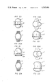
- FIG. 7 shows a closed spout of a container
- FIG. 8 shows an open spout
- FIG. 9 shows another embodiment of a closed spout
- FIG. 10 shows the spout of FIG. 9 after being opened
- FIG. 10A shows a needle and cover assembly applied to the spout
- FIG. 11 shows a perspective view of a container similar to the container in FIG. 1, however, having a more cylindrical shape and fitted with a grip for a squeezing finger,
- FIG. 12 shows partly in section a container similar to the container in FIG. 11 but modified such that it has a dished circular bead, designed to act as a member for scraping substances as may be sticking to the walls when emptying the container,
- FIG. 12A is a top view of FIG. 12,
- FIGS. 13 and 14 show details of the container of FIG. 12 in two different operational stages
- FIG. 15 shows an exploded view of the bottom part of a container having an opening with a screw cap
- FIG. 16 shows a perspective view, partly in section, of a container similar to the container of FIG. 12, where both the top-part and the bottom-part are made of flexible material and where the bottom-part is partly enclosed by an envelope of hard material,
- FIGS. 17 and 18 show modifications of the top part of a container and more particularly elements for pressing down the top-part toward the bottom-part
- FIG. 19 shows a member on the outside of the top-part of a container, said member acting as a locking device for holding the top-part in position when pressed on by a finger,
- FIG. 20 shows an elevational view of a container similar to FIG. 1 but of cylindrical configuration
- FIG. 20A is a top view of FIG. 20,
- FIG. 21 shows a cylglobid shape container having a flat bottom
- FIG. 21A is a bottom view of FIG. 21,
- FIG. 22 shows a side view of a cylovid shaped container
- FIG. 22A is a top view of FIG. 22,
- FIG. 23 shows a side view of a container having a cyleliden shape
- FIG. 23A is a top view of FIG. 23,
- FIG. 24 shows a container similar to the one shown in FIG. 11 but with a top-part having a spiral-shaped bead acting as a spring
- FIG. 24A is a top view of FIG. 24,
- FIG. 24B is a bottom view of FIG. 24,
- FIG. 25 shows the same container as in FIG. 24 but with a different spiral head
- FIG. 25A is a top view of FIG. 25,
- FIG. 25B is a bottom view of FIG. 25,
- FIG. 26 shows a perspective view of a squeezing device for a container according to one or several of shown embodiments
- FIG. 27 shows a perspective view of the same container as shown in FIG. 1 seen at an angle from the side, the grips for resting the fingers being rectangular so that a number of containers by joints between these grips can form a block,
- FIG. 27A is a top view of FIG. 27,
- FIG. 28 shows a side view of a container according to FIG. 27,
- FIG. 28A is a bottom view of FIG. 27,
- FIG. 29 shows a number of containers forming a block which can be slid into a box
- FIG. 30 shows a unit containing a number of the boxes shown in FIG. 29.
- reference numeral 1 refers to a dome-shaped part which is made of soft and ductile material.
- Numeral 2 refers also to a dome-shaped part, which is made of stiffer material and meant to retain its shape.
- the two dome-shaped parts are joined to each other at their openings as shown in FIG. 1, forming a container which is mainly spherical.
- the two joined parts can have any other shape. They could be, for example, cubical, rectangular or pyramidal; in other words the shape of the two joined parts can be varied in various ways.
- the two parts can, for example, be cylindrical and the free ends closed by hemispherical parts.
- the dome-shaped part 2 has a sealed spout 3 which can be opened when desired.
- an encircling lug which is elliptical such that the two lips or flanges 4 and 5 are formed.
- the lug can be given any suitable shape. It is suitable to minimize the size of the dome-shaped parts in order to facilitate the use of the container as shown in FIGS. 3 and 4.
- To the spout 3 any suitable means can be connected for applying the substance leaving the spout. Consequently, a hypodermic needle can be connected to the container, when it contains a liquid substance.
- a flexible or stiff tube could be connected to the container.
- FIGS. 7 and 8 there is shown a spout 3, which has a sealing 6, which together with the spout forms a single unit. This type of sealing can be cut off as shown in FIG. 8.
- FIG. 9 shows a spout 3', which is sealed by a cap 6', which is tied by a link 7a to the spout 3', alternatively, the cap could be tied by the link to the container.
- FIG. 9 shows the spout 3' sealed by the cap and FIG. 10 when the cap is removed.
- the container according to the invention is such that the dome-shaped part 1 can, by squeezing or the like, take the shape shown in FIG. 2; in other words the wall of the dome-shaped part 1 is flexible so that it can adjust to a lesser or greater extent, to the inside of the dome-shaped part 2.
- Any materials can be used which fulfill the function shown in FIGS. 1 and 2.
- a suitable material both for parts 1 and 2 would be a plastic, where the plastic in part 1 is flexible and that in part 2 be rather stiff.
- part 2 to be made of metal and part 1 of metal foil. Combinations such as stiff and thin cardboard or glass and rubber are also possible.
- part 1 It is practicable to construct the wall of part 1 in such a way that when the container has been squeezed, the wall remains as is just before the squeezing is completed.
- elements such as for example, ribs of suitable material could be molded as integral parts of part 1.
- additional elements such that the dome-shaped part 1 has a tendency to instantly switch over to the position shown in FIG. 2, when triggered by pressure on top of part 1.
- the container as described is, for example, used in the following way.
- the user opens the spout 3', eventually he connects something thereto, for example, a tube or a hypodermic needle; and then he squeezes the container as shown in FIG. 3.
- the container is fitted with a hypodermic needle 8. Holding the container as shown in FIG. 3, the needle is inserted in the part of the body to receive the injection.
- the user uses his thumb to press the top of the dome-shaped part 1 as shown in FIG. 4, the pressure being applied until part 1 is in the position shown in FIGS. 2 and 4, whereby the container is emptied.
- the flanges 4 and 5 serve as a gripping means for applying counter-pressure to the dispenser as shown in FIGS. 3 and 4.
- the counter pressure of the fingers on flanges 4 and 5 acts outside the periphery of the dome-shaped parts 1 and 2 thereby affording stability for the dispenser; also the action of the counterpressure at the level of the connection of the dome-shaped portions keeps the fingers of the user away from hypodermic needle 8 as seen in FIGS. 3 and 4; additionally, it is evident from FIGS. 3 and 4 that the presence of the flanges 4 and 5 insure that pressure application by the thumb will be limited to dome-shaped part 1.
- FIG. 10A shows a hypodermic needle and cover assembly applied to the opened spout 3.
- the spout 3 has a removable hypodermic needle unit 8" sealably pressed thereon, and a cover 6A removably engaged on needle unit 8".
- the cover 6A is removed from the needle unit and the container is emptied in the manner shown in FIG. 3.
- the assembly of needle unit 8" and cover 6A can be furnished in a sealed, sterile package which is opened to gain access to the assembly. Then the assembly is mounted on the opened spout and the cover 6A is removed.
- the needle unit 8" comprises a hypodermic needle 8A and a cuff portion 8B of flexible material, such as rubber or plastic, which can be tightly engaged on the spout.
- FIG. 11 shows a container similar to that described above where both dome-shaped parts are indicated respectively at 1' and 2'. They differ from the dome-shaped parts shown above in that they are cylindrical and one end of each part forms a hemisphere.
- the dome-shaped part 1' has on its top a protuberance 7 suitably shaped to be pressed by a finger.
- the protuberance can of course have a smooth surface, but it is preferred that the surface have such properties that a finger of the user will not slip when pressing the container.
- the container in FIG. 12 differs from that in FIG. 11 in that the dome-shaped part 1' has a recessed circular bead 8' preferably situated where the cylindrical shape turns into the hemispherical shape.
- the hemispherical part of the dome-shaped part 1' is indicated by numeral 1A.
- the circular bead 8' is designed to act as a member for scraping the substance sticking to the walls when emptying the container. This is especially shown in FIG. 14, when part 1A is pressed down. It shows how the circular bead 8' fits into the cylindrical part of the container.
- FIG. 16 shows a container made in one piece which is indicated by numeral 12.
- the shape of the container is similar to the container according to FIG. 11.
- the container 12 is made of flexible material and in order to have necessary rigidity, the end with the spout has an envelope 13 of hard material.
- the envelope has two flanges 4" and 5" for the fingers, similar to the flanges 4' and 5'.
- the envelope also has an opening 14 for the spout.
- the container has a circular bead 8' as described in connection with FIG. 11 and also a protuberance 7'.
- FIG. 17 shows how the top-part 1' can have an integrally moulded spiral 15, the objective of which is to distribute the applied pressure to a greater area of the top of part 1' when emptying the container.
- FIG. 18 shows another integrally molded element 16 having the same function as the spiral in FIG. 17.
- FIGS. 17 and 18 can be made of any material as long as they function as desired.
- FIG. 19 shows the top-part of a container according to FIG. 12 fitted with a disc 17 shaped somewhat like a plate and with its outer edge pointing out from the container.
- the disc has a hole matching and fixed to the protuberance 7 on the part 1A.
- the disc can be made of any suitable material, for example, plastic or metal and it may be resilient.
- the purpose of the disc 17 is to act as a catching device inside the cylinder being formed when part 1' is pushed. When pressure on the protuberance 7 ceases the disc 17 prevent the part 1' from springing back. How the cylinder is deformed is, for example, shown in FIG. 14.
- the containers according to FIG. 1 or to FIG. 11 naturally can be used in a device containing a plunger replacing a human thumb.
- FIG. 20 shows a container having a central part 27 of a length H, which central part preferably has a non-circular cross section.
- a container can be made having a cylindrical central part with hemispheres as top-part 1 and bottom-part 2. (See FIG. 11.)
- This embodiment, having the length H greater than zero, is referred to as a cylglobid and embodiment 1. If the length H is equal to zero, the container becomes the same as shown in FIG. 1.
- FIG. 21 shows the same container as in FIG. 20 but where the bottom-part 2" has a large opening covered by a lid 28.
- FIGS. 22 and 23 are given shapes which are optimal with regard to adaptations to fingers, when using the thumb together with the index finger and the middle finger for emptying the container.
- the top-part 1" is adopted to the shape of the thumb.
- the fingerprint of the thumb in combination with the cross-section of the tip of the thumb forms a volume similar to half an egg cut from tip to tip.
- the embodiment having the length H greater then zero, as shown in the Figure, is known as a cylovid.
- FIG. 23 shows a container having a top-part 1''' and a bottom-part 2''' each part being shaped as a semi-ellipsoid cut along the largest diameter.
- FIG. 24 shows a container corresponding to the one shown in FIG. 11.
- a spiral-shaped bead 29 On the top-part 1 IV is arranged a spiral-shaped bead 29.
- the container has, like the ones previously described, a part 7 IV for a thumb and two flanges 4 and 5, for gripping by the forefinger and the middle finger when used, and additionally a bottom-part 2 IV .
- the bottom-part has an opening 9' which can be sealed with a cap 10'.
- the spiral-shaped bead 29 gives resistance to the pressure from a thumb, facilitating conditions for a smooth and controlled application of the substance stored in the container.
- FIG. 25 shows a container having exactly the same properties as the container in FIG. 24, but where the single bead is modified such that the top-part has a number of beads as shown.
- FIG. 26 shows another device for emptying a container according to the invention.
- the device has a cylindrical cap 18, which at its open end has a circular pocket 21 formed by a double-folded corbelled rim 19 and 20.
- the circular pocket 21 is intended to surround the flanges 4' and 5' of a container 1', 2'.
- the cap 18 is fitted with a plunger 22 which has a press plate 23 and a finger part 24.
- the unit is placed between two fingers in such a way that part 20 of the rim is gripped by said fingers. The thumb is put on the fingerpart 24, and by pressing the plunger 22, the container 1', 2' is emptied.
- the spout 3 can be made cylindrical and provided with threads 9 as shown in FIG. 15.
- a cap 10 can be mounted on the spout by corresponding threads 11.
- FIGS. 27 and 28 show a container having a top-part 1 V and a bottom-part 2 V .
- the container has two flanges 4 V and 5 V together forming a rectangular surface.
- the bottom-part 2 V has an opening with a sealing member 10 V which is cylindrical and prevents the container from staying upright on a horizontal surface.
- a number of containers can be joined to each other, forming an assembly as shown in FIG. 29. Between the flanges are indications of fracture making it possible to break off one container at a time from the block.
- assemblies of containers By making assemblies of containers, these assemblies can conveniently be packed in boxes 31 which can form multiple packages enclosed in wrapping 32, such as, for example, thermoplastic foil.
- the bottom-parts together with the flanges can be made in one step in one tool, after which this part is fitted with the top-parts, separately made or equally made as one unit.
Abstract
A method of dispensing fluid or semi-fluid liquids or pastes in which the liquid or paste is contained in a container having a top flexible dome and a bottom dome connected at their open ends to each other. The method comprises pressing the top dome downwardly toward the bottom dome and forcing the top dome into the bottom dome and discharging the liquid or paste from the bottom dome under the action of the forcing of the top dome into the bottom dome. The top dome can be formed with an internal annular bead which is displaced along the inner walls of the bottom dome to scrape off material stuck to the inside walls of the bottom dome.
Description
This application is a continuation-in-part of Ser. No. 661,177 filed Feb. 25, 1976, now U.S. Pat. No. 4,072,249.
This invention relates to a container for fluid or semi-fluid substances in small quantities and to methods of discharging materials using such container. The substances to be packed according to the invention are mainly drugs; consequently the following description deals with such substances. However, it should be obvious that other substances can be packed in the described container.
In administering drugs, it is common to pack them in conventional tubes. The medical doctors Mone Hall, Percy Nordquist, Eva Palmgren and Irene Wilhelmsson have reported in a study at the National Medical Conference 1974 in Sweden that the conventional tube, irrespective of material used, is very difficult to handle, especially for older people. The test tubes used by the doctors have been of various types of existing tubes, containing substances having pharmacological effects. The study is considered to be highly representative for the kind of problems appearing in the use of tubes, and it is related in Svensk Lakartidning 1975 (Swedish Medical Journal).
Tubes are sometimes intended for one-time use and sometimes for repeated use. The tube always is such that by squeezing, a predetermined amount of the substance can be applied on a desired location of the patient. However, experience has shown that it is completely impossible to meet this requirement by using conventional tubes.
In the periodical Nord Emballage, Feb. 1975, Vol. 2, page 4, it is mentioned that it is possible to get more exact doses by using a specially designed valve. This is, of course, an improvement, but patients have difficulty in handling these tubes equipped with such valves. These kinds of tubes are also expensive, which is a serious disadvantage considering the large consumption of tubes in hospitals.
An object of this invention is to provide a container, which a patient, irrespective of age, can handle without difficulty.
According to the invention, the container can be placed between two fingers, and a thumb can be used to squeeze the contents out of the container. The container, according to the invention, has flanges such that it can be grasped by, for example, the index finger and the middle finger. Due to these flanges, it is also possible to manufacture an assembly of containers, where the containers are joined to each other by the flanges. In the joints between containers, there shall be indications of fracture, facilitating the separation of one container from the assembly and which can be used by the patient. By having the containers joined to each other, they form units which can easily fit into boxes. Packages containing several boxes can have such dimensions that a number of packages can form units of multiple packages. Subsequently, the handling of containers from factory to hospital becomes simpler.
A container according to this invention contains a top-part, a bottom-part, and protruding members forming the flanges that are gripped by the fingers when being squeezed. The bottom-part is normally made of rigid material and the top-part of flexible material. Both the top- and bottom-parts have a domed shape, preferably spherical or the like. Naturally, both parts can be made of flexible material, but then there must be arranged a rigid envelope having the protruding members thereon and which would envelope, to a lesser or greater degree, the bottom-part. According to the invention, it is appropriate for the top-part to be fitted with some type of a member for keeping a thumb securely in place. Such a member can be a friction lining or a particular shape of the upper part.
The top-part might also contain a member, as for example, a spring or other element of metal, arranged such that the position of the top-part remains after having been squeezed.
The container may also have permanent rib shaped deformations or the like, such that squeezing the top-part is made against a retaining force.
The top-part of the container might have a circular member arranged such that when the container is squeezed, this circular member scrapes substances sticking to the walls.
The bottom part of the container may have an opening which can be sealed with a cap. The bottom-part may have any kind of appropriate opening for emptying the container. The opening may be small or large and can be sealed by a cap having a locking device or threads.
The container according to the invention can also be fitted in a special device having a plunger such that the contents can be squeezed out by the plunger. This special device can also have means such that it can be gripped by the fingers and normally can take the place of the corresponding means of the container.
According to the invention, it is advantageous to make a number of bottom-parts forming one piece and then to fit the top-parts. The separate containers in such a unit can be filled with substance at the same time, for example, via the bottom-parts, and when using this method it is possible for the top-parts to be initially fully depressed into the bottom-part and that the substance used for filling is preheated.
The invention is described in greater detail in connection with the accompanying drawings, wherein:
FIG. 1 shows an embodiment of a container according to the invention, either filled or ready to be filled with a substance,
FIG. 2 shows the same container as in FIG. 1 but emptied,
FIG. 3 shows a gripped container in the form of a one-time syringe and just before the squeezing takes place,
FIG. 4 shows the container of FIG. 3 after it is emptied,
FIG. 5 shows a partial section of the container of FIG. 1,
FIG. 6 shows a section of the container shown in FIG. 2,
FIG. 7 shows a closed spout of a container,
FIG. 8 shows an open spout,
FIG. 9 shows another embodiment of a closed spout,
FIG. 10 shows the spout of FIG. 9 after being opened,
FIG. 10A shows a needle and cover assembly applied to the spout,
FIG. 11 shows a perspective view of a container similar to the container in FIG. 1, however, having a more cylindrical shape and fitted with a grip for a squeezing finger,
FIG. 12 shows partly in section a container similar to the container in FIG. 11 but modified such that it has a dished circular bead, designed to act as a member for scraping substances as may be sticking to the walls when emptying the container,
FIG. 12A is a top view of FIG. 12,
FIGS. 13 and 14 show details of the container of FIG. 12 in two different operational stages,
FIG. 15 shows an exploded view of the bottom part of a container having an opening with a screw cap,
FIG. 16 shows a perspective view, partly in section, of a container similar to the container of FIG. 12, where both the top-part and the bottom-part are made of flexible material and where the bottom-part is partly enclosed by an envelope of hard material,
FIGS. 17 and 18 show modifications of the top part of a container and more particularly elements for pressing down the top-part toward the bottom-part,
FIG. 19 shows a member on the outside of the top-part of a container, said member acting as a locking device for holding the top-part in position when pressed on by a finger,
FIG. 20 shows an elevational view of a container similar to FIG. 1 but of cylindrical configuration,
FIG. 20A is a top view of FIG. 20,
FIG. 21 shows a cylglobid shape container having a flat bottom,
FIG. 21A is a bottom view of FIG. 21,
FIG. 22 shows a side view of a cylovid shaped container,
FIG. 22A is a top view of FIG. 22,
FIG. 23 shows a side view of a container having a cyleliden shape,
FIG. 23A is a top view of FIG. 23,
FIG. 24 shows a container similar to the one shown in FIG. 11 but with a top-part having a spiral-shaped bead acting as a spring,
FIG. 24A is a top view of FIG. 24,
FIG. 24B is a bottom view of FIG. 24,
FIG. 25 shows the same container as in FIG. 24 but with a different spiral head,
FIG. 25A is a top view of FIG. 25,
FIG. 25B is a bottom view of FIG. 25,
FIG. 26 shows a perspective view of a squeezing device for a container according to one or several of shown embodiments,
FIG. 27 shows a perspective view of the same container as shown in FIG. 1 seen at an angle from the side, the grips for resting the fingers being rectangular so that a number of containers by joints between these grips can form a block,
FIG. 27A is a top view of FIG. 27,
FIG. 28 shows a side view of a container according to FIG. 27,
FIG. 28A is a bottom view of FIG. 27,
FIG. 29 shows a number of containers forming a block which can be slid into a box, and
FIG. 30 shows a unit containing a number of the boxes shown in FIG. 29.
In the drawing, reference numeral 1 refers to a dome-shaped part which is made of soft and ductile material. Numeral 2 refers also to a dome-shaped part, which is made of stiffer material and meant to retain its shape. The two dome-shaped parts are joined to each other at their openings as shown in FIG. 1, forming a container which is mainly spherical. However, it is obvious that the two joined parts can have any other shape. They could be, for example, cubical, rectangular or pyramidal; in other words the shape of the two joined parts can be varied in various ways. The two parts can, for example, be cylindrical and the free ends closed by hemispherical parts. It can be suitable to make a flat top on one of the dome-shaped parts, whereby the container can be placed on a table top or the like without rolling. The dome-shaped part 2 has a sealed spout 3 which can be opened when desired. At the joint between the two dome-shaped parts is an encircling lug which is elliptical such that the two lips or flanges 4 and 5 are formed. Naturally, the lug can be given any suitable shape. It is suitable to minimize the size of the dome-shaped parts in order to facilitate the use of the container as shown in FIGS. 3 and 4. To the spout 3 any suitable means can be connected for applying the substance leaving the spout. Consequently, a hypodermic needle can be connected to the container, when it contains a liquid substance. A flexible or stiff tube could be connected to the container.
In FIGS. 7 and 8 there is shown a spout 3, which has a sealing 6, which together with the spout forms a single unit. This type of sealing can be cut off as shown in FIG. 8.
FIG. 9 shows a spout 3', which is sealed by a cap 6', which is tied by a link 7a to the spout 3', alternatively, the cap could be tied by the link to the container. FIG. 9 shows the spout 3' sealed by the cap and FIG. 10 when the cap is removed.
The container according to the invention is such that the dome-shaped part 1 can, by squeezing or the like, take the shape shown in FIG. 2; in other words the wall of the dome-shaped part 1 is flexible so that it can adjust to a lesser or greater extent, to the inside of the dome-shaped part 2. Any materials can be used which fulfill the function shown in FIGS. 1 and 2. A suitable material both for parts 1 and 2 would be a plastic, where the plastic in part 1 is flexible and that in part 2 be rather stiff. Naturally it is also possible for part 2 to be made of metal and part 1 of metal foil. Combinations such as stiff and thin cardboard or glass and rubber are also possible.
It is practicable to construct the wall of part 1 in such a way that when the container has been squeezed, the wall remains as is just before the squeezing is completed. To this end, elements, such as for example, ribs of suitable material could be molded as integral parts of part 1. It is also possible to include additional elements such that the dome-shaped part 1 has a tendency to instantly switch over to the position shown in FIG. 2, when triggered by pressure on top of part 1.
The container as described is, for example, used in the following way. The user opens the spout 3', eventually he connects something thereto, for example, a tube or a hypodermic needle; and then he squeezes the container as shown in FIG. 3. In FIGS. 3 and 4, the container is fitted with a hypodermic needle 8. Holding the container as shown in FIG. 3, the needle is inserted in the part of the body to receive the injection. Now the user uses his thumb to press the top of the dome-shaped part 1 as shown in FIG. 4, the pressure being applied until part 1 is in the position shown in FIGS. 2 and 4, whereby the container is emptied. The flanges 4 and 5 serve as a gripping means for applying counter-pressure to the dispenser as shown in FIGS. 3 and 4. As seen in these figures, the counter pressure of the fingers on flanges 4 and 5 acts outside the periphery of the dome-shaped parts 1 and 2 thereby affording stability for the dispenser; also the action of the counterpressure at the level of the connection of the dome-shaped portions keeps the fingers of the user away from hypodermic needle 8 as seen in FIGS. 3 and 4; additionally, it is evident from FIGS. 3 and 4 that the presence of the flanges 4 and 5 insure that pressure application by the thumb will be limited to dome-shaped part 1.
FIG. 10A shows a hypodermic needle and cover assembly applied to the opened spout 3. Namely, as seen in FIG. 10A, the spout 3 has a removable hypodermic needle unit 8" sealably pressed thereon, and a cover 6A removably engaged on needle unit 8". In use, the cover 6A is removed from the needle unit and the container is emptied in the manner shown in FIG. 3. The assembly of needle unit 8" and cover 6A can be furnished in a sealed, sterile package which is opened to gain access to the assembly. Then the assembly is mounted on the opened spout and the cover 6A is removed. The needle unit 8" comprises a hypodermic needle 8A and a cuff portion 8B of flexible material, such as rubber or plastic, which can be tightly engaged on the spout.
FIG. 11 shows a container similar to that described above where both dome-shaped parts are indicated respectively at 1' and 2'. They differ from the dome-shaped parts shown above in that they are cylindrical and one end of each part forms a hemisphere. The dome-shaped part 1' has on its top a protuberance 7 suitably shaped to be pressed by a finger. The protuberance can of course have a smooth surface, but it is preferred that the surface have such properties that a finger of the user will not slip when pressing the container.
The container in FIG. 12 differs from that in FIG. 11 in that the dome-shaped part 1' has a recessed circular bead 8' preferably situated where the cylindrical shape turns into the hemispherical shape. The hemispherical part of the dome-shaped part 1' is indicated by numeral 1A. The circular bead 8' is designed to act as a member for scraping the substance sticking to the walls when emptying the container. This is especially shown in FIG. 14, when part 1A is pressed down. It shows how the circular bead 8' fits into the cylindrical part of the container.
FIG. 16 shows a container made in one piece which is indicated by numeral 12. The shape of the container is similar to the container according to FIG. 11. The container 12 is made of flexible material and in order to have necessary rigidity, the end with the spout has an envelope 13 of hard material. The envelope has two flanges 4" and 5" for the fingers, similar to the flanges 4' and 5'. The envelope also has an opening 14 for the spout. The container has a circular bead 8' as described in connection with FIG. 11 and also a protuberance 7'.
FIG. 17 shows how the top-part 1' can have an integrally moulded spiral 15, the objective of which is to distribute the applied pressure to a greater area of the top of part 1' when emptying the container.
FIG. 18 shows another integrally molded element 16 having the same function as the spiral in FIG. 17.
The two elements in FIGS. 17 and 18 can be made of any material as long as they function as desired.
FIG. 19 shows the top-part of a container according to FIG. 12 fitted with a disc 17 shaped somewhat like a plate and with its outer edge pointing out from the container. In the center, the disc has a hole matching and fixed to the protuberance 7 on the part 1A. The disc can be made of any suitable material, for example, plastic or metal and it may be resilient. The purpose of the disc 17 is to act as a catching device inside the cylinder being formed when part 1' is pushed. When pressure on the protuberance 7 ceases the disc 17 prevent the part 1' from springing back. How the cylinder is deformed is, for example, shown in FIG. 14.
The containers according to FIG. 1 or to FIG. 11 naturally can be used in a device containing a plunger replacing a human thumb.
FIG. 20 shows a container having a central part 27 of a length H, which central part preferably has a non-circular cross section. However, a container can be made having a cylindrical central part with hemispheres as top-part 1 and bottom-part 2. (See FIG. 11.) This embodiment, having the length H greater than zero, is referred to as a cylglobid and embodiment 1. If the length H is equal to zero, the container becomes the same as shown in FIG. 1.
FIG. 21 shows the same container as in FIG. 20 but where the bottom-part 2" has a large opening covered by a lid 28.
The embodiments according to the FIGS. 22 and 23 are given shapes which are optimal with regard to adaptations to fingers, when using the thumb together with the index finger and the middle finger for emptying the container.
In FIG. 22, the top-part 1" is adopted to the shape of the thumb. The fingerprint of the thumb in combination with the cross-section of the tip of the thumb forms a volume similar to half an egg cut from tip to tip. When the container is made with a central part 27 and a top-part and a bottom-part shaped like said volume, it will be easy using the thumb, the index and the middle fingers to press the top-part 1" through the central part 28 down to the corresponding bottom-part 2". The spout is preferably positioned in the lowest area of the bottom-part. If the container is made without a central part, which is the same as H=zero, it takes the shape of an egg. The embodiment having the length H greater then zero, as shown in the Figure, is known as a cylovid.
FIG. 23 shows a container having a top-part 1''' and a bottom-part 2''' each part being shaped as a semi-ellipsoid cut along the largest diameter. When such top- and bottom-parts are joined with a central part 27, an embodiment is formed called a cylelid. If the length H of the central part is equal to zero, the shape of the container will be an ellipsoid.
Common for all the embodiments according to the FIGS. 20-23 is that when H is greater than zero, the top- and bottom-parts are separated by an envelope surface forming the central part, which envelope surface is theoretically formed when a generatrix is moved perpendicular to and along all of the envelope of the maximum cross section of an end part.
FIG. 24 shows a container corresponding to the one shown in FIG. 11. On the top-part 1IV is arranged a spiral-shaped bead 29. The container has, like the ones previously described, a part 7IV for a thumb and two flanges 4 and 5, for gripping by the forefinger and the middle finger when used, and additionally a bottom-part 2IV. The bottom-part has an opening 9' which can be sealed with a cap 10'. The spiral-shaped bead 29 gives resistance to the pressure from a thumb, facilitating conditions for a smooth and controlled application of the substance stored in the container.
FIG. 25 shows a container having exactly the same properties as the container in FIG. 24, but where the single bead is modified such that the top-part has a number of beads as shown.
FIG. 26 shows another device for emptying a container according to the invention. The device has a cylindrical cap 18, which at its open end has a circular pocket 21 formed by a double-folded corbelled rim 19 and 20. The circular pocket 21 is intended to surround the flanges 4' and 5' of a container 1', 2'. The cap 18 is fitted with a plunger 22 which has a press plate 23 and a finger part 24. For emptying a container according to this invention using a device as described, the unit is placed between two fingers in such a way that part 20 of the rim is gripped by said fingers. The thumb is put on the fingerpart 24, and by pressing the plunger 22, the container 1', 2' is emptied.
The spout 3 can be made cylindrical and provided with threads 9 as shown in FIG. 15. A cap 10 can be mounted on the spout by corresponding threads 11.
Again, it should be noted that all the flanges of the container adapted to the fingers are made so that the emptying is done smoothly and controllably. This implies that the design has to be based on an empirical study of the fingers and their physiological coordination. Embodiments and sizes of said containers should be designed taking a number of parameters into consideration, such as for example, length, angle, surface and size of finger tips, finger joints, and all the fingers in order to have optimal effects and as few types as possible.
FIGS. 27 and 28 show a container having a top-part 1V and a bottom-part 2V. The container has two flanges 4V and 5V together forming a rectangular surface. The bottom-part 2V has an opening with a sealing member 10V which is cylindrical and prevents the container from staying upright on a horizontal surface. Because of the rectangular shape of the flanges, a number of containers can be joined to each other, forming an assembly as shown in FIG. 29. Between the flanges are indications of fracture making it possible to break off one container at a time from the block. By making assemblies of containers, these assemblies can conveniently be packed in boxes 31 which can form multiple packages enclosed in wrapping 32, such as, for example, thermoplastic foil.
When manufacturing the assemblies according to FIG. 29, the bottom-parts together with the flanges can be made in one step in one tool, after which this part is fitted with the top-parts, separately made or equally made as one unit.
Claims (8)
1. A method of dispensing fluid or semi-fluid liquids or pastes in which said liquid or paste is contained in a container having a top flexible dome and a bottom dome connected at their open ends to each other and a laterally projecting gripping means at the connection of the open ends of the domes, the bottom dome having a closed spout remote from the open end thereof, said method comprising: forming an opening in said spout, affixing a hypodermic needle to said spout at said opening, pressing said top dome downwardly toward said bottom dome and forcing said top dome into said bottom dome while applying counter-pressure to the gripping means, and discharging said liquid or paste from said bottom dome through the open spout and hypodermic needle under the action of the forcing of the top dome into the bottom dome and the application of the counter-pressure to the gripping means, said counter-pressure acting outside the periphery of the domes whereby to provide stability while also acting at the level of the connection of the domes whereby the fingers of the user are remote from the hypodermic needle, the gripping means also serving to limit the pressing action to the top dome.
2. The method according to claim 1 wherein the needle is removably affixed to the spout.
3. The method according to claim 1 comprising temporarily covering the needle prior to discharge of the material.
4. A method of dispensing fluid or semi-fluid liquids or pastes in which said liquid or paste is contained in a container having a top flexible dome and a bottom come connected at their open ends to each other and a laterally projecting gripping means at a connection of the open ends of the domes, the bottom dome having a closed spout remote from the open end thereof, said method comprising forming an opening in said spout, removably affixing a hypodermic needle to the spout at said opening, forming a cuff on the hypodermic needle for tightly engaging the spout, pressing said top dome downwardly toward said bottom dome and forcing said top dome into said bottom dome while applying counter-pressure to the gripping means, and discharging said liquid or paste from said bottom dome through the open spout and hypodermic needle under the action of the forcing of the top dome into the bottom dome and the application of the counter-pressure to the gripping means, said counter-pressure acting outside the periphery of the domes whereby to provide stability while also acting at the level of the connection of the domes whereby the fingers of the user are remote from the hypodermic needle, the gripping means also serving to limit the pressing action to the top dome.
5. A method of dispensing fluid or semi-fluid liquids or pastes in which said liquid or paste is contained in a container having a top flexible dome and a bottom dome connected at their open ends to each other, said method comprising: pressing said top dome downwardly toward said bottom dome and forcing said top dome into said bottom dome, and discharging said liquid or paste from said bottom dome under the action of the forcing of the top dome into the bottom dome, said step of pressing said top dome comprising scraping off material stuck to the inside walls of said bottom dome for discharge of said material.
6. The method according to claim 5 wherein said step of pressing further comprises gripping flanges mounted about the connected open ends of said top and bottom domes with two fingers, and pressing downwardly on the top of said top dome with a thumb.
7. A method of dispensing fluid or semi-fluid liquids or pastes in which said liquid or paste is contained in a container having a top flexible dome and a bottom dome connected at their open ends to each other, said method comprising: pressing said top dome downwardly toward said bottom dome and forcing said top dome into said bottom dome, and discharging said liquid or paste from said bottom dome under the action of the forcing of the top dome into the bottom dome, said top dome being formed with an internal annular bead which is displaced along the inner walls of the bottom dome to scrape material therefrom as the top dome is pressed into the bottom dome.
8. The method according to claim 7 wherein said top dome is deformed inwardly when pressure is applied thereto.
Applications Claiming Priority (2)
| Application Number | Priority Date | Filing Date | Title |
|---|---|---|---|
| SE7502318 | 1975-03-03 | ||
| SE7502318A SE7502318L (en) | 1975-03-03 | 1975-03-03 | PACKAGING FOR LIQUID FOR SEMI-SOLID MATERIAL, SUITABLE FOR SMALLER QUANTITIES |
Related Parent Applications (1)
| Application Number | Title | Priority Date | Filing Date |
|---|---|---|---|
| US05/661,177 Continuation-In-Part US4072249A (en) | 1975-03-03 | 1976-02-25 | Container suitable for smaller quantities of fluid or semi-fluid substances |
Publications (1)
| Publication Number | Publication Date |
|---|---|
| US4282986A true US4282986A (en) | 1981-08-11 |
Family
ID=20323832
Family Applications (2)
| Application Number | Title | Priority Date | Filing Date |
|---|---|---|---|
| US05/661,177 Expired - Lifetime US4072249A (en) | 1975-03-03 | 1976-02-25 | Container suitable for smaller quantities of fluid or semi-fluid substances |
| US05/861,843 Expired - Lifetime US4282986A (en) | 1975-03-03 | 1977-12-19 | Method for discharge of quantities of fluid or semi-fluid substances from a container |
Family Applications Before (1)
| Application Number | Title | Priority Date | Filing Date |
|---|---|---|---|
| US05/661,177 Expired - Lifetime US4072249A (en) | 1975-03-03 | 1976-02-25 | Container suitable for smaller quantities of fluid or semi-fluid substances |
Country Status (11)
| Country | Link |
|---|---|
| US (2) | US4072249A (en) |
| JP (1) | JPS51143481A (en) |
| CA (1) | CA1047459A (en) |
| CH (1) | CH605328A5 (en) |
| DE (1) | DE2608794A1 (en) |
| DK (1) | DK141895B (en) |
| FR (1) | FR2302936A1 (en) |
| GB (1) | GB1539598A (en) |
| IN (1) | IN145108B (en) |
| NL (1) | NL7602203A (en) |
| SE (1) | SE7502318L (en) |
Cited By (56)
| Publication number | Priority date | Publication date | Assignee | Title |
|---|---|---|---|---|
| US4397879A (en) * | 1982-07-14 | 1983-08-09 | Warren Wilson | Apparatus for and method of making funnel cakes |
| US4522622A (en) * | 1982-12-23 | 1985-06-11 | Alza Corporation | Multiple fluid pulse dispenser |
| WO1988002266A1 (en) * | 1986-09-23 | 1988-04-07 | Nastech Pharmaceutical Company, Inc. | Liquid medicine container and method |
| US4817800A (en) * | 1987-05-20 | 1989-04-04 | Surgikos, Inc. | Fluid injection system cassette and fluid packaging methods |
| US4928852A (en) * | 1983-01-28 | 1990-05-29 | Michel Guiffray | Container of flexible material for receiving a liquid |
| US4955871A (en) * | 1987-04-29 | 1990-09-11 | Path | Single-use disposable syringe |
| EP0411578A1 (en) * | 1989-08-01 | 1991-02-06 | Terumo Kabushiki Kaisha | Liquid applicator |
| US5102398A (en) * | 1990-09-18 | 1992-04-07 | Farris Barry L | Plungerless syringe |
| US5261881A (en) * | 1990-03-28 | 1993-11-16 | R. Myles Riner, M.D., Professional Corporation | Non-reusable dispensing apparatus |
| US5370626A (en) * | 1990-09-18 | 1994-12-06 | Farris; Barry | Plungerless syringe |
| US5538506A (en) * | 1993-11-03 | 1996-07-23 | Farris; Barry | Prefilled fluid syringe |
| US5582330A (en) * | 1994-12-28 | 1996-12-10 | Allergan, Inc. | Specific volume dispenser |
| US5609580A (en) * | 1994-09-16 | 1997-03-11 | Vital Signs, Inc. | Injection holder for a plungerless syringe and combination plungerless syringe and injection holder |
| US5713874A (en) * | 1995-08-01 | 1998-02-03 | Kind-R-Ject Company, Llc | Camouflaged injection needle |
| US5957895A (en) * | 1998-02-20 | 1999-09-28 | Becton Dickinson And Company | Low-profile automatic injection device with self-emptying reservoir |
| US6062413A (en) * | 1996-01-23 | 2000-05-16 | Redmond; Sanford | Reclosable dispenser package, reclosable outlet forming structure and method and apparatus for making same |
| USD432647S (en) * | 1999-02-25 | 2000-10-24 | Barry Farris | No reflux syringe |
| USD432646S (en) * | 1999-02-26 | 2000-10-24 | Barry Farris | Syringe with air trap |
| US6251098B1 (en) | 1992-01-24 | 2001-06-26 | I-Flow, Corp. | Fluid container for use with platen pump |
| US6296150B1 (en) | 1999-02-25 | 2001-10-02 | Barry Farris | Medicinal dosing apparatus and method |
| US6299012B1 (en) * | 1996-01-23 | 2001-10-09 | Sanford Redmond | Reclosable dispenser package, reclosable outlet forming structure and method and apparatus for making same |
| US6358239B1 (en) | 1992-01-24 | 2002-03-19 | I-Flow Corporation | Platen pump |
| US6391003B1 (en) | 1999-10-25 | 2002-05-21 | Antares Pharma, Inc. | Locking mechanism for a jet injector |
| US6428528B2 (en) | 1998-08-11 | 2002-08-06 | Antares Pharma, Inc. | Needle assisted jet injector |
| US20040220537A1 (en) * | 1994-08-30 | 2004-11-04 | Pharmacia Aktiebolag | Ocular treatment device |
| US20040217084A1 (en) * | 2003-04-29 | 2004-11-04 | Tetra Laval Holdings & Finance, S.A. | Collapsible semi-rigid container |
| US20050171477A1 (en) * | 2002-05-23 | 2005-08-04 | Seedlings Life Science Ventures | Apparatus and method for rapid auto-injection of medication |
| US20060169278A1 (en) * | 2002-07-09 | 2006-08-03 | Djupesland Per G | Delivery devices |
| US20070191792A1 (en) * | 2003-12-08 | 2007-08-16 | Galderma S.A. | Device for dosing a product that is intended to be applied to the skin |
| US20070260188A1 (en) * | 2006-05-03 | 2007-11-08 | Seratouch, L.L.C. | Closure container for single dose disposable pharmaceutical delivery system |
| US20080215029A1 (en) * | 1993-01-22 | 2008-09-04 | I-Flow Corporation | Platen pump |
| EP2161216A1 (en) * | 2008-03-18 | 2010-03-10 | Delo Industrieklebstoffe Gmbh & Co. Kg Aa | Container for flowable substances and method for non-porous metering of such substances |
| US20100252577A1 (en) * | 2006-06-08 | 2010-10-07 | Seaquist Perfect Dispensing Gmbh | Dispensing device |
| US20110121006A1 (en) * | 2004-08-31 | 2011-05-26 | John Nottingham | Collapsible container with stowed component |
| WO2011026050A3 (en) * | 2009-08-30 | 2011-07-28 | Aktivpak, Inc. | Dispensing device along with method for dispensing product |
| WO2014035935A1 (en) * | 2012-08-27 | 2014-03-06 | Ultradent Products, Inc. | Ampoule dispenser |
| US8915889B2 (en) | 2008-08-05 | 2014-12-23 | Antares Pharma, Inc. | Multiple dosage injector |
| US8945063B2 (en) | 2009-03-20 | 2015-02-03 | Antares Pharma, Inc. | Hazardous agent injection system |
| US20150122840A1 (en) * | 2013-11-06 | 2015-05-07 | The Procter & Gamble Company | Flexible containers having flexible valves |
| WO2015121275A1 (en) * | 2014-02-12 | 2015-08-20 | Sanofi-Aventis Deutschland Gmbh | Compressible reservoir for liquid medicament |
| WO2015121276A1 (en) * | 2014-02-12 | 2015-08-20 | Sanofi-Aventis Deutschland Gmbh | Reservoir for liquid medicament |
| US9180259B2 (en) | 2005-01-24 | 2015-11-10 | Antares Pharma, Inc. | Prefilled syringe jet injector |
| US9220660B2 (en) | 2011-07-15 | 2015-12-29 | Antares Pharma, Inc. | Liquid-transfer adapter beveled spike |
| US9333309B2 (en) | 2002-02-11 | 2016-05-10 | Antares Pharma, Inc. | Intradermal injector |
| US9364610B2 (en) | 2012-05-07 | 2016-06-14 | Antares Pharma, Inc. | Injection device with cammed ram assembly |
| US9408984B2 (en) | 2009-09-15 | 2016-08-09 | Becton, Dickinson And Company | Self-injection device |
| US9446195B2 (en) | 2011-07-15 | 2016-09-20 | Antares Pharma, Inc. | Injection device with cammed ram assembly |
| US9707354B2 (en) | 2013-03-11 | 2017-07-18 | Antares Pharma, Inc. | Multiple dosage injector with rack and pinion dosage system |
| US9744302B2 (en) | 2013-02-11 | 2017-08-29 | Antares Pharma, Inc. | Needle assisted jet injection device having reduced trigger force |
| US9808582B2 (en) | 2006-05-03 | 2017-11-07 | Antares Pharma, Inc. | Two-stage reconstituting injector |
| US9850046B2 (en) | 2013-11-06 | 2017-12-26 | The Procter & Gamble Company | Flexible containers with vent systems |
| US9849247B2 (en) | 2010-02-01 | 2017-12-26 | Becton, Dickinson And Company | Low dose prefilled drug delivery device and method |
| US9950125B2 (en) | 2012-04-06 | 2018-04-24 | Antares Pharma, Inc. | Needle assisted jet injection administration of testosterone compositions |
| US9988190B2 (en) | 2015-04-10 | 2018-06-05 | The Procter & Gamble Company | Flexible containers with biased dispensing |
| US10017300B2 (en) | 2015-04-10 | 2018-07-10 | The Procter & Gamble Company | Flexible containers with product dispensing visibility |
| US10433820B2 (en) * | 2015-10-15 | 2019-10-08 | Ronan Murphy | Biopsy transport device and method |
Families Citing this family (40)
| Publication number | Priority date | Publication date | Assignee | Title |
|---|---|---|---|---|
| GB1583157A (en) * | 1976-05-07 | 1981-01-21 | Kenova Ab | Syringes |
| DE2831913C2 (en) * | 1978-07-20 | 1985-06-13 | Müller's Mühle Schneekoppe AG, 4650 Gelsenkirchen | Storage bottle for the dosed delivery of a partial amount of the filled liquid |
| JPS5766762A (en) * | 1980-10-08 | 1982-04-23 | Kishio Nanjiyou | Syringe |
| DE3101683A1 (en) * | 1981-01-20 | 1983-02-24 | Erich Dipl.-Ing. 2190 Cuxhaven Chronz | Container to be opened by the pressure of two fingers |
| GB2120630A (en) * | 1982-05-21 | 1983-12-07 | Dey Lab Inc | Squeezable liquid-dispensing containers |
| US4758219A (en) * | 1985-05-17 | 1988-07-19 | Microvasive, Inc. | Enteral feeding device |
| US4909801A (en) * | 1986-06-16 | 1990-03-20 | Acorn Laboratories, Inc. | Eyedrop dispenser having a bumper |
| GB2208639B (en) * | 1987-02-12 | 1991-05-29 | Ici Plc | A capsule for use in introducing additive into a closed container |
| GB2200888B (en) * | 1987-02-12 | 1991-05-29 | Ici Plc | A closed container into which additive can be introduced |
| US4826481A (en) * | 1987-05-27 | 1989-05-02 | Abbott Labs. | Enteral feeding device |
| JPS6433070U (en) * | 1987-08-22 | 1989-03-01 | ||
| DE3734306A1 (en) * | 1987-10-10 | 1989-04-27 | Pfeiffer Erich Gmbh & Co Kg | DISCHARGE DEVICE FOR FLOWABLE MEDIA |
| US4890744A (en) * | 1988-10-28 | 1990-01-02 | W. A. Lane, Inc. | Easy open product pouch |
| US5033631A (en) * | 1990-02-08 | 1991-07-23 | Harold Nightingale | Method and apparatus for expelling air from a flexible liner baby nursing bottle |
| US5478315A (en) * | 1994-08-08 | 1995-12-26 | Brothers Family Investments, L.C. | Local anesthetic injection system |
| US5645527A (en) * | 1996-02-09 | 1997-07-08 | Iomed, Inc. | Hydration assembly for hydrating a bioelectrode element |
| FR2750678B1 (en) * | 1996-07-05 | 1998-10-30 | Valois | DEVICE FOR BIPHASIC DELIVERY OF A SINGLE DOSE |
| US5862949A (en) * | 1996-09-27 | 1999-01-26 | Lever Brothers Company, Division Of Conopco, Inc. | Dual container and individual chamber therefor |
| DE29618751U1 (en) * | 1996-10-29 | 1997-02-06 | Pickerd Gmbh & Co H | Sales pack for food ingredients |
| NL1005295C2 (en) * | 1997-02-17 | 1998-08-18 | Rompa Kunststofprodukten B V | Presentation element. |
| GB2351272B (en) * | 1999-06-23 | 2001-05-02 | Eu Pharma Ltd | Oral medicine dispenser |
| JP2003517348A (en) * | 1999-08-03 | 2003-05-27 | フアーマシア・アー・ベー | Liquid discharge container |
| US6730066B1 (en) | 1999-08-03 | 2004-05-04 | Pharmacia Ab | Liquid delivery container |
| US7014068B1 (en) * | 1999-08-23 | 2006-03-21 | Ben Z. Cohen | Microdispensing pump |
| AR029768A1 (en) * | 1999-10-18 | 2003-07-16 | Novartis Ag | PLASTIC PACKAGE FOR A PHARMACEUTICAL PRODUCT AND METHOD TO MANUFACTURE AND STERILIZE A PHARMACEUTICAL PACKAGE |
| US7080644B2 (en) | 2000-06-28 | 2006-07-25 | Microdose Technologies, Inc. | Packaging and delivery of pharmaceuticals and drugs |
| JP2003261174A (en) * | 2002-03-06 | 2003-09-16 | Idemitsu Unitech Co Ltd | Flowable substance package |
| WO2005100208A1 (en) * | 2004-04-15 | 2005-10-27 | Satoshi Anzai | Extrusion type container |
| US20080163610A1 (en) * | 2007-01-05 | 2008-07-10 | Matthew Thomas Baird | Method and system for regenerating exhaust system filtering and catalyst components using variable high engine idle |
| US8182683B1 (en) * | 2009-05-15 | 2012-05-22 | Allen Russell E | Portable fluid dispenser |
| ES1071029Y (en) | 2009-09-03 | 2010-03-05 | Lekue S L | PRACTICABLE FLEXIBLE APPLICATOR CONTAINER |
| MY187036A (en) | 2010-01-05 | 2021-08-27 | Microdose Therapeutx Inc | Inhalation device and method |
| DE102010033015B4 (en) * | 2010-07-31 | 2016-03-17 | Gaplast Gmbh | Single-use applicator |
| US20130292414A1 (en) * | 2012-05-02 | 2013-11-07 | Spencer D. Sutherland | Dispensing Device |
| US10010685B2 (en) * | 2012-06-26 | 2018-07-03 | Becton, Dickinson And Company | Single use delivery device having a primer element |
| US9555915B2 (en) * | 2013-08-01 | 2017-01-31 | Joshua Wettergreen | Dispenser display having a plurality of independent dispensing bodies |
| US10675452B2 (en) * | 2014-03-10 | 2020-06-09 | 3M Innovative Properties Company | Micro-needle device |
| CA3073530A1 (en) * | 2017-08-24 | 2019-02-28 | Spencer D. Sutherland | Dispensing device |
| FR3087365B1 (en) * | 2018-10-17 | 2020-11-27 | Coradin Sas | DEVICE FOR PACKING AT LEAST ONE FLUID |
| DE102020106955B4 (en) | 2020-03-13 | 2022-08-04 | Aesculap Ag | Medical packaging insert, medical packaging system and method of packaging a medical object |
Citations (6)
| Publication number | Priority date | Publication date | Assignee | Title |
|---|---|---|---|---|
| US798093A (en) * | 1904-05-11 | 1905-08-29 | Edward F Dean | Hypodermic syringe. |
| US2768623A (en) * | 1954-12-29 | 1956-10-30 | John F Marchand | Container for liquids, and more particularly to a container which incorporates therein the function of a syringe |
| GB790220A (en) * | 1954-09-14 | 1958-02-05 | Adolfo Scholcoff Elinger | Hypodermic syringe ampulla |
| US3145879A (en) * | 1961-04-03 | 1964-08-25 | Lumelite Corp | Container with self contained dispensing means |
| US3473524A (en) * | 1966-02-08 | 1969-10-21 | Britampoula Ag | Syringe ampoules |
| US4131217A (en) * | 1977-05-19 | 1978-12-26 | Landstingens Inkopscentral, L I C | Device for emptying a container |
Family Cites Families (11)
| Publication number | Priority date | Publication date | Assignee | Title |
|---|---|---|---|---|
| US2899110A (en) * | 1959-08-11 | Parker | ||
| US2428577A (en) * | 1945-09-06 | 1947-10-07 | Waddy T Mathis | Liquid-measuring dispenser |
| US2771071A (en) * | 1953-09-12 | 1956-11-20 | Mann Gerhard | Ampulla structure |
| US3155281A (en) * | 1962-04-09 | 1964-11-03 | Questron America Inc | Container |
| US3154074A (en) * | 1962-10-23 | 1964-10-27 | Lehn & Fink Products Corp | Internal medicament applicator |
| GB1095316A (en) * | 1963-08-08 | 1967-12-13 | Arthur Bane | Improvements in ampoules for surgical hypodermic syringes |
| US3295523A (en) * | 1963-10-17 | 1967-01-03 | Biolog Res Inc | Disposable syringe with novel rebounding squeeze bulb |
| US3592360A (en) * | 1967-06-28 | 1971-07-13 | Arde Inc | Cylindrical fluid storage and expulsion tank |
| US3567463A (en) * | 1969-02-06 | 1971-03-02 | Theodore M Williams | Food flavoring packet for containers |
| US3626939A (en) * | 1970-02-16 | 1971-12-14 | Harry M Sokolic | Disposable douche with nesting bellows sections |
| US3851571A (en) * | 1972-08-28 | 1974-12-03 | Nichols Prod Inc | Apparatus and method for encapsulating eggs |
-
1975
- 1975-03-03 SE SE7502318A patent/SE7502318L/en unknown
-
1976
- 1976-02-25 US US05/661,177 patent/US4072249A/en not_active Expired - Lifetime
- 1976-02-26 IN IN348/CAL/76A patent/IN145108B/en unknown
- 1976-02-27 DK DK84076AA patent/DK141895B/en unknown
- 1976-03-01 JP JP51022561A patent/JPS51143481A/en active Pending
- 1976-03-02 CA CA246,993A patent/CA1047459A/en not_active Expired
- 1976-03-02 CH CH257076A patent/CH605328A5/xx not_active IP Right Cessation
- 1976-03-02 FR FR7605805A patent/FR2302936A1/en active Granted
- 1976-03-02 GB GB8345/76A patent/GB1539598A/en not_active Expired
- 1976-03-03 NL NL7602203A patent/NL7602203A/en not_active Application Discontinuation
- 1976-03-03 DE DE19762608794 patent/DE2608794A1/en not_active Withdrawn
-
1977
- 1977-12-19 US US05/861,843 patent/US4282986A/en not_active Expired - Lifetime
Patent Citations (6)
| Publication number | Priority date | Publication date | Assignee | Title |
|---|---|---|---|---|
| US798093A (en) * | 1904-05-11 | 1905-08-29 | Edward F Dean | Hypodermic syringe. |
| GB790220A (en) * | 1954-09-14 | 1958-02-05 | Adolfo Scholcoff Elinger | Hypodermic syringe ampulla |
| US2768623A (en) * | 1954-12-29 | 1956-10-30 | John F Marchand | Container for liquids, and more particularly to a container which incorporates therein the function of a syringe |
| US3145879A (en) * | 1961-04-03 | 1964-08-25 | Lumelite Corp | Container with self contained dispensing means |
| US3473524A (en) * | 1966-02-08 | 1969-10-21 | Britampoula Ag | Syringe ampoules |
| US4131217A (en) * | 1977-05-19 | 1978-12-26 | Landstingens Inkopscentral, L I C | Device for emptying a container |
Cited By (116)
| Publication number | Priority date | Publication date | Assignee | Title |
|---|---|---|---|---|
| US4397879A (en) * | 1982-07-14 | 1983-08-09 | Warren Wilson | Apparatus for and method of making funnel cakes |
| US4522622A (en) * | 1982-12-23 | 1985-06-11 | Alza Corporation | Multiple fluid pulse dispenser |
| US4928852A (en) * | 1983-01-28 | 1990-05-29 | Michel Guiffray | Container of flexible material for receiving a liquid |
| WO1988002266A1 (en) * | 1986-09-23 | 1988-04-07 | Nastech Pharmaceutical Company, Inc. | Liquid medicine container and method |
| US4955871A (en) * | 1987-04-29 | 1990-09-11 | Path | Single-use disposable syringe |
| US4817800A (en) * | 1987-05-20 | 1989-04-04 | Surgikos, Inc. | Fluid injection system cassette and fluid packaging methods |
| EP0411578A1 (en) * | 1989-08-01 | 1991-02-06 | Terumo Kabushiki Kaisha | Liquid applicator |
| US5054948A (en) * | 1989-08-01 | 1991-10-08 | Terumo Kabushiki Kaisha | Liquid applicator |
| US5261881A (en) * | 1990-03-28 | 1993-11-16 | R. Myles Riner, M.D., Professional Corporation | Non-reusable dispensing apparatus |
| US5370626A (en) * | 1990-09-18 | 1994-12-06 | Farris; Barry | Plungerless syringe |
| US5102398A (en) * | 1990-09-18 | 1992-04-07 | Farris Barry L | Plungerless syringe |
| US6251098B1 (en) | 1992-01-24 | 2001-06-26 | I-Flow, Corp. | Fluid container for use with platen pump |
| US20040108333A1 (en) * | 1992-01-24 | 2004-06-10 | Rake Kenneth W. | Platen pump |
| US6871759B2 (en) | 1992-01-24 | 2005-03-29 | I-Flow Corporation | Platen pump |
| US6358239B1 (en) | 1992-01-24 | 2002-03-19 | I-Flow Corporation | Platen pump |
| US7337922B2 (en) | 1992-01-24 | 2008-03-04 | I-Flow Corporation | Platen pump |
| US20050211725A1 (en) * | 1992-01-24 | 2005-09-29 | Rake Kenneth W | Platen pump |
| US7083068B2 (en) | 1992-01-24 | 2006-08-01 | I-Flow Corporation | Platen pump |
| US20080215029A1 (en) * | 1993-01-22 | 2008-09-04 | I-Flow Corporation | Platen pump |
| US5538506A (en) * | 1993-11-03 | 1996-07-23 | Farris; Barry | Prefilled fluid syringe |
| US20040220537A1 (en) * | 1994-08-30 | 2004-11-04 | Pharmacia Aktiebolag | Ocular treatment device |
| US5609580A (en) * | 1994-09-16 | 1997-03-11 | Vital Signs, Inc. | Injection holder for a plungerless syringe and combination plungerless syringe and injection holder |
| US5582330A (en) * | 1994-12-28 | 1996-12-10 | Allergan, Inc. | Specific volume dispenser |
| US5713874A (en) * | 1995-08-01 | 1998-02-03 | Kind-R-Ject Company, Llc | Camouflaged injection needle |
| US20020000441A1 (en) * | 1996-01-23 | 2002-01-03 | Sanford Redmond | Reclosable dispenser package, reclosable outlet forming structure and method and apparatus for making same |
| US6299012B1 (en) * | 1996-01-23 | 2001-10-09 | Sanford Redmond | Reclosable dispenser package, reclosable outlet forming structure and method and apparatus for making same |
| US6062413A (en) * | 1996-01-23 | 2000-05-16 | Redmond; Sanford | Reclosable dispenser package, reclosable outlet forming structure and method and apparatus for making same |
| US5957895A (en) * | 1998-02-20 | 1999-09-28 | Becton Dickinson And Company | Low-profile automatic injection device with self-emptying reservoir |
| US20040220524A1 (en) * | 1998-08-11 | 2004-11-04 | Antares Pharma, Inc. | Needle assisted jet injector |
| US6428528B2 (en) | 1998-08-11 | 2002-08-06 | Antares Pharma, Inc. | Needle assisted jet injector |
| US6565553B2 (en) | 1998-08-11 | 2003-05-20 | Antares Pharma, Inc. | Needle assisted jet injector |
| US6746429B2 (en) | 1998-08-11 | 2004-06-08 | Antares Pharma, Inc. | Needle assisted jet injector |
| USRE44847E1 (en) | 1998-08-11 | 2014-04-15 | Antares Pharma, Inc. | Needle assisted jet injector |
| US7744582B2 (en) | 1998-08-11 | 2010-06-29 | Antares Pharma, Inc. | Needle assisted jet injector |
| US6547099B1 (en) | 1999-02-25 | 2003-04-15 | Barry Farris | Medicinal dosing apparatus and method |
| USD432647S (en) * | 1999-02-25 | 2000-10-24 | Barry Farris | No reflux syringe |
| US6296150B1 (en) | 1999-02-25 | 2001-10-02 | Barry Farris | Medicinal dosing apparatus and method |
| USD432646S (en) * | 1999-02-26 | 2000-10-24 | Barry Farris | Syringe with air trap |
| US6391003B1 (en) | 1999-10-25 | 2002-05-21 | Antares Pharma, Inc. | Locking mechanism for a jet injector |
| US9333309B2 (en) | 2002-02-11 | 2016-05-10 | Antares Pharma, Inc. | Intradermal injector |
| US9737670B2 (en) | 2002-02-11 | 2017-08-22 | Antares Pharma, Inc. | Intradermal injector |
| US20050171477A1 (en) * | 2002-05-23 | 2005-08-04 | Seedlings Life Science Ventures | Apparatus and method for rapid auto-injection of medication |
| US6979316B1 (en) | 2002-05-23 | 2005-12-27 | Seedlings Life Science Ventures Llc | Apparatus and method for rapid auto-injection of medication |
| US7658724B2 (en) | 2002-05-23 | 2010-02-09 | Seedings Life Science Ventures LLC | Apparatus and method for rapid auto-injection of medication |
| US20060169278A1 (en) * | 2002-07-09 | 2006-08-03 | Djupesland Per G | Delivery devices |
| US7934503B2 (en) * | 2002-07-09 | 2011-05-03 | Optinose As | Delivery devices |
| US7059487B2 (en) | 2003-04-29 | 2006-06-13 | Tetra Laval Holdings & Finance, Sa | Collapsible semi-rigid container |
| US20040217084A1 (en) * | 2003-04-29 | 2004-11-04 | Tetra Laval Holdings & Finance, S.A. | Collapsible semi-rigid container |
| US20070191792A1 (en) * | 2003-12-08 | 2007-08-16 | Galderma S.A. | Device for dosing a product that is intended to be applied to the skin |
| US7727204B2 (en) * | 2003-12-08 | 2010-06-01 | Galderma S.A. | Device for dosing a product that is intended to be applied to the skin |
| US20110121006A1 (en) * | 2004-08-31 | 2011-05-26 | John Nottingham | Collapsible container with stowed component |
| US20110121007A1 (en) * | 2004-08-31 | 2011-05-26 | John Nottingham | Collapsible container that expands when water is added |
| US20110127276A1 (en) * | 2004-08-31 | 2011-06-02 | John Nottingham | Collapsible container with z-shaped hinge |
| US11446441B2 (en) | 2005-01-24 | 2022-09-20 | Antares Pharma, Inc. | Prefilled syringe injector |
| US9629959B2 (en) | 2005-01-24 | 2017-04-25 | Antares Pharma, Inc. | Prefilled syringe jet injector |
| US9180259B2 (en) | 2005-01-24 | 2015-11-10 | Antares Pharma, Inc. | Prefilled syringe jet injector |
| US10478560B2 (en) | 2005-01-24 | 2019-11-19 | Antares Pharma, Inc. | Prefilled syringe injector |
| US7892211B2 (en) | 2006-05-03 | 2011-02-22 | Seratouch, L.L.C. | Closure container for single dose disposable pharmaceutical delivery system |
| US9808582B2 (en) | 2006-05-03 | 2017-11-07 | Antares Pharma, Inc. | Two-stage reconstituting injector |
| US20070260188A1 (en) * | 2006-05-03 | 2007-11-08 | Seratouch, L.L.C. | Closure container for single dose disposable pharmaceutical delivery system |
| US20110196338A1 (en) * | 2006-05-03 | 2011-08-11 | Seratouch, Llc | Closure container for single dose disposable pharmaceutical delivery system |
| US20090247954A1 (en) * | 2006-05-03 | 2009-10-01 | Seartouch Llc | Closure container for single dose disposable pharmaceutical delivery system |
| US10688250B2 (en) | 2006-05-03 | 2020-06-23 | Antares Pharma, Inc. | Two-stage reconstituting injector |
| US11547808B2 (en) | 2006-05-03 | 2023-01-10 | Antares Pharma, Inc. | Two-stage reconstituting injector |
| US8573449B2 (en) * | 2006-06-08 | 2013-11-05 | Aptar Dortmund Gmbh | Dispensing device having an elastically deformable section for pumping a fluid |
| US20100252577A1 (en) * | 2006-06-08 | 2010-10-07 | Seaquist Perfect Dispensing Gmbh | Dispensing device |
| EP2161216A1 (en) * | 2008-03-18 | 2010-03-10 | Delo Industrieklebstoffe Gmbh & Co. Kg Aa | Container for flowable substances and method for non-porous metering of such substances |
| US8955720B2 (en) | 2008-03-18 | 2015-02-17 | DELO Industrieklebstoffe GmbH & Co. KGaA | Container for flowable substances and dispensing apparatus |
| US20100308075A1 (en) * | 2008-03-18 | 2010-12-09 | DELO Industrieklebstoffe GmbH & Co. KGaA | Container for flowable substances and dispensing apparatus |
| US8915889B2 (en) | 2008-08-05 | 2014-12-23 | Antares Pharma, Inc. | Multiple dosage injector |
| US10555954B2 (en) | 2009-03-20 | 2020-02-11 | Antares Pharma, Inc. | Hazardous agent injection system |
| US8945063B2 (en) | 2009-03-20 | 2015-02-03 | Antares Pharma, Inc. | Hazardous agent injection system |
| US11497753B2 (en) | 2009-03-20 | 2022-11-15 | Antares Pharma, Inc. | Hazardous agent injection system |
| US9750881B2 (en) | 2009-03-20 | 2017-09-05 | Antares Pharma, Inc. | Hazardous agent injection system |
| CN102712408A (en) * | 2009-08-30 | 2012-10-03 | 阿克蒂弗派克股份有限公司 | Dispensing device along with method for dispensing product |
| WO2011026050A3 (en) * | 2009-08-30 | 2011-07-28 | Aktivpak, Inc. | Dispensing device along with method for dispensing product |
| US9408984B2 (en) | 2009-09-15 | 2016-08-09 | Becton, Dickinson And Company | Self-injection device |
| US10898648B2 (en) | 2010-02-01 | 2021-01-26 | Becton, Dickinson And Company | Low dose prefilled drug delivery device and method |
| US9849247B2 (en) | 2010-02-01 | 2017-12-26 | Becton, Dickinson And Company | Low dose prefilled drug delivery device and method |
| US11738150B2 (en) | 2010-02-01 | 2023-08-29 | Becton, Dickinson And Company | Low dose prefilled drug delivery device and method |
| US9446195B2 (en) | 2011-07-15 | 2016-09-20 | Antares Pharma, Inc. | Injection device with cammed ram assembly |
| US10568809B2 (en) | 2011-07-15 | 2020-02-25 | Ferring B.V. | Liquid-transfer adapter beveled spike |
| US10279131B2 (en) | 2011-07-15 | 2019-05-07 | Antares Pharma, Inc. | Injection device with cammed RAM assembly |
| US9220660B2 (en) | 2011-07-15 | 2015-12-29 | Antares Pharma, Inc. | Liquid-transfer adapter beveled spike |
| US11185642B2 (en) | 2011-07-15 | 2021-11-30 | Antares Pharma, Inc. | Injection device with cammed ram assembly |
| US10821072B2 (en) | 2012-04-06 | 2020-11-03 | Antares Pharma, Inc. | Needle assisted jet injection administration of testosterone compositions |
| US9950125B2 (en) | 2012-04-06 | 2018-04-24 | Antares Pharma, Inc. | Needle assisted jet injection administration of testosterone compositions |
| US11771646B2 (en) | 2012-04-06 | 2023-10-03 | Antares Pharma, Inc. | Needle assisted jet injection administration of testosterone compositions |
| US9364610B2 (en) | 2012-05-07 | 2016-06-14 | Antares Pharma, Inc. | Injection device with cammed ram assembly |
| US11446440B2 (en) | 2012-05-07 | 2022-09-20 | Antares Pharma, Inc. | Needle assisted injection device having reduced trigger force |
| US9364611B2 (en) | 2012-05-07 | 2016-06-14 | Antares Pharma, Inc. | Needle assisted jet injection device having reduced trigger force |
| US10357609B2 (en) | 2012-05-07 | 2019-07-23 | Antares Pharma, Inc. | Needle assisted jet injection device having reduced trigger force |
| US10905827B2 (en) | 2012-05-07 | 2021-02-02 | Antares Pharma, Inc. | Injection device with cammed ram assembly |
| WO2014035935A1 (en) * | 2012-08-27 | 2014-03-06 | Ultradent Products, Inc. | Ampoule dispenser |
| US11813435B2 (en) | 2013-02-11 | 2023-11-14 | Antares Pharma, Inc. | Needle assisted injection device having reduced trigger force |
| US10881798B2 (en) | 2013-02-11 | 2021-01-05 | Antares Pharma, Inc. | Needle assisted injection device having reduced trigger force |
| US9744302B2 (en) | 2013-02-11 | 2017-08-29 | Antares Pharma, Inc. | Needle assisted jet injection device having reduced trigger force |
| US11628260B2 (en) | 2013-03-11 | 2023-04-18 | Antares Pharma, Inc. | Multiple dosage injector with rack and pinion dosage system |
| US9707354B2 (en) | 2013-03-11 | 2017-07-18 | Antares Pharma, Inc. | Multiple dosage injector with rack and pinion dosage system |
| US10610649B2 (en) | 2013-03-11 | 2020-04-07 | Antares Pharma, Inc. | Multiple dosage injector with rack and pinion dosage system |
| US9694965B2 (en) * | 2013-11-06 | 2017-07-04 | The Procter & Gamble Company | Flexible containers having flexible valves |
| US20150122840A1 (en) * | 2013-11-06 | 2015-05-07 | The Procter & Gamble Company | Flexible containers having flexible valves |
| US20170259984A1 (en) * | 2013-11-06 | 2017-09-14 | The Procter & Gamble Company | Flexible containers having flexible valves |
| US10138049B2 (en) * | 2013-11-06 | 2018-11-27 | The Procter & Gamble Company | Flexible containers having flexible valves |
| US9850046B2 (en) | 2013-11-06 | 2017-12-26 | The Procter & Gamble Company | Flexible containers with vent systems |
| US20170007500A1 (en) * | 2014-02-12 | 2017-01-12 | Sanofi-Aventis Deutschland Gmbh | Reservoir for liquid medicament |
| CN105979923A (en) * | 2014-02-12 | 2016-09-28 | 赛诺菲-安万特德国有限公司 | Reservoir for liquid medicament |
| US11419984B2 (en) * | 2014-02-12 | 2022-08-23 | Sanofi-Aventis Deutschland Gmbh | Compressible reservoir for liquid medicament |
| CN105979981A (en) * | 2014-02-12 | 2016-09-28 | 赛诺菲-安万特德国有限公司 | Compressible reservoir for liquid medicament |
| US10874588B2 (en) * | 2014-02-12 | 2020-12-29 | Sanofi-Aventis Deutschland Gmbh | Reservoir for liquid medicament |
| US20170007767A1 (en) * | 2014-02-12 | 2017-01-12 | Sanofi-Aventis Deutschland Gmbh | Compressible reservoir for liquid medicament |
| WO2015121276A1 (en) * | 2014-02-12 | 2015-08-20 | Sanofi-Aventis Deutschland Gmbh | Reservoir for liquid medicament |
| WO2015121275A1 (en) * | 2014-02-12 | 2015-08-20 | Sanofi-Aventis Deutschland Gmbh | Compressible reservoir for liquid medicament |
| US10017300B2 (en) | 2015-04-10 | 2018-07-10 | The Procter & Gamble Company | Flexible containers with product dispensing visibility |
| US9988190B2 (en) | 2015-04-10 | 2018-06-05 | The Procter & Gamble Company | Flexible containers with biased dispensing |
| US10433820B2 (en) * | 2015-10-15 | 2019-10-08 | Ronan Murphy | Biopsy transport device and method |
Also Published As
| Publication number | Publication date |
|---|---|
| FR2302936A1 (en) | 1976-10-01 |
| CA1047459A (en) | 1979-01-30 |
| US4072249A (en) | 1978-02-07 |
| DE2608794A1 (en) | 1976-09-16 |
| DK84076A (en) | 1976-09-04 |
| CH605328A5 (en) | 1978-09-29 |
| SE7502318L (en) | 1976-09-06 |
| DK141895C (en) | 1980-11-24 |
| GB1539598A (en) | 1979-01-31 |
| FR2302936B1 (en) | 1979-04-20 |
| NL7602203A (en) | 1976-09-07 |
| JPS51143481A (en) | 1976-12-09 |
| IN145108B (en) | 1978-08-26 |
| DK141895B (en) | 1980-07-14 |
Similar Documents
| Publication | Publication Date | Title |
|---|---|---|
| US4282986A (en) | Method for discharge of quantities of fluid or semi-fluid substances from a container | |
| EP0196288B1 (en) | Dosage package | |
| JP2983192B2 (en) | Icing set | |
| US5012956A (en) | Squeeze bottle with bag, dispensing system | |
| US7597497B2 (en) | Single dose tooth whitener dispenser and applicator, and method of tooth whitening | |
| US5588563A (en) | Quantitative dispenser | |
| US4169547A (en) | Ointment container with finger actuated piston | |
| JPH02180278A (en) | Applying implement and packing assembly therefor | |
| JPH05270577A (en) | Dosing dispenser | |
| US2814420A (en) | Sealed package and container providing the same | |
| JPH02233384A (en) | Distributor for viscous material | |
| US1592584A (en) | Collapsible container | |
| JP2571710B2 (en) | Dispensing container | |
| US4657159A (en) | Meniscus-shaped container | |
| US3135302A (en) | Bottle dropper and closure | |
| US3954207A (en) | Dosage dispenser | |
| CN215460210U (en) | Leakage-proof liquid weight bottle | |
| JPH074216Y2 (en) | Container | |
| JPS6132700Y2 (en) | ||
| CN214711040U (en) | Ann bottle is pressed to liquid powder | |
| EP4094844A1 (en) | Dispenser | |
| WO1998034581A1 (en) | Closed simple tubular container | |
| WO1999051184A1 (en) | Easily opened elongated tubular container | |
| US20230192346A1 (en) | Assembly composed of a container for a fluid and a dispenser packaging | |
| US20210380328A1 (en) | Device for packaging at least one fluid |
Legal Events
| Date | Code | Title | Description |
|---|---|---|---|
| STCF | Information on status: patent grant |
Free format text: PATENTED CASE |
|
| AS | Assignment |
Owner name: ESTATE OF PERCY NORDQVIST C/O PER NORDQVIST, LAMME Free format text: ASSIGNMENT OF ASSIGNORS INTEREST.;ASSIGNOR:LANDSTINGENS INKOPSCENTRAL;REEL/FRAME:004982/0627 Effective date: 19880803 Owner name: BO THURESSON AF EKENSTAM, AKERGATAN 5,431 39 MOLND Free format text: ASSIGNMENT OF ASSIGNORS INTEREST.;ASSIGNOR:LANDSTINGENS INKOPSCENTRAL;REEL/FRAME:004982/0627 Effective date: 19880803 |