US4281680A - Swing check valve construction - Google Patents
Swing check valve construction Download PDFInfo
- Publication number
- US4281680A US4281680A US06/067,325 US6732579A US4281680A US 4281680 A US4281680 A US 4281680A US 6732579 A US6732579 A US 6732579A US 4281680 A US4281680 A US 4281680A
- Authority
- US
- United States
- Prior art keywords
- seat
- clapper
- hub member
- check valve
- swing check
- Prior art date
- Legal status (The legal status is an assumption and is not a legal conclusion. Google has not performed a legal analysis and makes no representation as to the accuracy of the status listed.)
- Expired - Lifetime
Links
Images

Classifications
-
- F—MECHANICAL ENGINEERING; LIGHTING; HEATING; WEAPONS; BLASTING
- F16—ENGINEERING ELEMENTS AND UNITS; GENERAL MEASURES FOR PRODUCING AND MAINTAINING EFFECTIVE FUNCTIONING OF MACHINES OR INSTALLATIONS; THERMAL INSULATION IN GENERAL
- F16K—VALVES; TAPS; COCKS; ACTUATING-FLOATS; DEVICES FOR VENTING OR AERATING
- F16K27/00—Construction of housing; Use of materials therefor
- F16K27/10—Welded housings
-
- F—MECHANICAL ENGINEERING; LIGHTING; HEATING; WEAPONS; BLASTING
- F16—ENGINEERING ELEMENTS AND UNITS; GENERAL MEASURES FOR PRODUCING AND MAINTAINING EFFECTIVE FUNCTIONING OF MACHINES OR INSTALLATIONS; THERMAL INSULATION IN GENERAL
- F16K—VALVES; TAPS; COCKS; ACTUATING-FLOATS; DEVICES FOR VENTING OR AERATING
- F16K1/00—Lift valves or globe valves, i.e. cut-off apparatus with closure members having at least a component of their opening and closing motion perpendicular to the closing faces
- F16K1/16—Lift valves or globe valves, i.e. cut-off apparatus with closure members having at least a component of their opening and closing motion perpendicular to the closing faces with pivoted closure-members
- F16K1/18—Lift valves or globe valves, i.e. cut-off apparatus with closure members having at least a component of their opening and closing motion perpendicular to the closing faces with pivoted closure-members with pivoted discs or flaps
- F16K1/20—Lift valves or globe valves, i.e. cut-off apparatus with closure members having at least a component of their opening and closing motion perpendicular to the closing faces with pivoted closure-members with pivoted discs or flaps with axis of rotation arranged externally of valve member
- F16K1/2042—Special features or arrangements of the sealing
- F16K1/2057—Special features or arrangements of the sealing the sealing being arranged on the valve seat
-
- F—MECHANICAL ENGINEERING; LIGHTING; HEATING; WEAPONS; BLASTING
- F16—ENGINEERING ELEMENTS AND UNITS; GENERAL MEASURES FOR PRODUCING AND MAINTAINING EFFECTIVE FUNCTIONING OF MACHINES OR INSTALLATIONS; THERMAL INSULATION IN GENERAL
- F16K—VALVES; TAPS; COCKS; ACTUATING-FLOATS; DEVICES FOR VENTING OR AERATING
- F16K15/00—Check valves
- F16K15/02—Check valves with guided rigid valve members
- F16K15/03—Check valves with guided rigid valve members with a hinged closure member or with a pivoted closure member
- F16K15/034—Check valves with guided rigid valve members with a hinged closure member or with a pivoted closure member weight-loaded
-
- F—MECHANICAL ENGINEERING; LIGHTING; HEATING; WEAPONS; BLASTING
- F16—ENGINEERING ELEMENTS AND UNITS; GENERAL MEASURES FOR PRODUCING AND MAINTAINING EFFECTIVE FUNCTIONING OF MACHINES OR INSTALLATIONS; THERMAL INSULATION IN GENERAL
- F16K—VALVES; TAPS; COCKS; ACTUATING-FLOATS; DEVICES FOR VENTING OR AERATING
- F16K27/00—Construction of housing; Use of materials therefor
- F16K27/02—Construction of housing; Use of materials therefor of lift valves
- F16K27/0209—Check valves or pivoted valves
- F16K27/0227—Check valves or pivoted valves with the valve members swinging around an axis located at the edge of or outside the valve member
-
- Y—GENERAL TAGGING OF NEW TECHNOLOGICAL DEVELOPMENTS; GENERAL TAGGING OF CROSS-SECTIONAL TECHNOLOGIES SPANNING OVER SEVERAL SECTIONS OF THE IPC; TECHNICAL SUBJECTS COVERED BY FORMER USPC CROSS-REFERENCE ART COLLECTIONS [XRACs] AND DIGESTS
- Y10—TECHNICAL SUBJECTS COVERED BY FORMER USPC
- Y10T—TECHNICAL SUBJECTS COVERED BY FORMER US CLASSIFICATION
- Y10T137/00—Fluid handling
- Y10T137/7504—Removable valve head and seat unit
-
- Y—GENERAL TAGGING OF NEW TECHNOLOGICAL DEVELOPMENTS; GENERAL TAGGING OF CROSS-SECTIONAL TECHNOLOGIES SPANNING OVER SEVERAL SECTIONS OF THE IPC; TECHNICAL SUBJECTS COVERED BY FORMER USPC CROSS-REFERENCE ART COLLECTIONS [XRACs] AND DIGESTS
- Y10—TECHNICAL SUBJECTS COVERED BY FORMER USPC
- Y10T—TECHNICAL SUBJECTS COVERED BY FORMER US CLASSIFICATION
- Y10T137/00—Fluid handling
- Y10T137/7722—Line condition change responsive valves
- Y10T137/7837—Direct response valves [i.e., check valve type]
- Y10T137/7898—Pivoted valves
- Y10T137/7901—Valve head movably connected for accommodation to seat
-
- Y—GENERAL TAGGING OF NEW TECHNOLOGICAL DEVELOPMENTS; GENERAL TAGGING OF CROSS-SECTIONAL TECHNOLOGIES SPANNING OVER SEVERAL SECTIONS OF THE IPC; TECHNICAL SUBJECTS COVERED BY FORMER USPC CROSS-REFERENCE ART COLLECTIONS [XRACs] AND DIGESTS
- Y10—TECHNICAL SUBJECTS COVERED BY FORMER USPC
- Y10T—TECHNICAL SUBJECTS COVERED BY FORMER US CLASSIFICATION
- Y10T137/00—Fluid handling
- Y10T137/7722—Line condition change responsive valves
- Y10T137/7837—Direct response valves [i.e., check valve type]
- Y10T137/7898—Pivoted valves
- Y10T137/7903—Weight biased
Definitions
- Swing check valves are currently available for installation into large pipelines 24 inches in diameter and larger.
- One such check valve is shown in U.S. Pat. No. 3,897,804.
- the valve body is formed of spherical configuration, and separately formed cylindrical hubs, one of which carries a seat ring, are welded into body openings.
- the valve clapper is hinged to the valve body so as to swing down into closed position and seat firmly against the seat ring.
- attaining the accurate relationship between the clapper shaft center line and the sealing face between the seat and the clapper in order to insure proper seating, requires extremely tedious and accurate machine work while handling a heavy, bulky and unwieldy member, i.e. the complete valve body.
- the swing check valve is provided with a clapper, which in closed position seats firmly against a seat ring carried on a hub member welded into the valve body around a flow passage.
- the clapper is pivoted, not on the valve body, but on the hub member which carries the seat ring, and the positioning of the valve shaft is accomplished with the seat hub separate and apart from the valve body. After, proper adjustments are made, the valve clapper and the seat hub are inserted in the body and the seat hub is welded in place.
- FIG. 1 is a vertical section view of a swing check valve including an embodiment of this invention
- FIG. 2 is a partial vertical section view of a swing check valve including another embodiment of this invention.
- FIG. 3 is a section view taken along line 3--3 of FIG. 2.
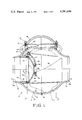
- the swing check valve 10 of this invention includes a spherical main body section 12 which may be fabricated from hemispherical sections, which are formed from steel plates or the like and welded together at 14 along a vertical great circle.
- the hemispherical sections are formed with upstream and downstream openings 16 and 18 which may be swaged outward to form hubs 20 and 22 of the ultimate pipeline diameter.
- the hubs 20 and 22 are finished at their ends 20a and 22a for welding into a pipeline, but is to be understood that they may be provided with flanges or otherwise prepared for pipeline installation.
- Suitable legs 24 may be welded to the spherical body 12 to support the valve erectly, particularly during manufacturing and shipping.
- a seat hub 26 is welded into the upstream hub 20 and an annular recess 28 is formed in the inner end thereof in order to accommodate a seat ring 30.
- the seat ring 30 is secured in place by set screws 32 and an O-ring 34 is provided to seal around the outer surface.
- a resilient seal ring such as an O-ring 36 is also provided as the main seal for sealing engagement with a clapper 38.
- the clapper 38 is preferably of spherical, dished configuration with a substantially radial outer border 40 that seats against the seat ring 30 when the clapper is in its closed position, as shown.
- the clapper may be reinforced with a disc 42, which is welded across the concave portion thereof, the disc being provided with openings 44 to balance fluid pressure across it.
- a cylindrical hub or boss 46 is welded to the back of the clapper 38 and slidably receives the clapper arm 48 which is keyed to a shaft 50.
- the shaft 50 is rotatable in a complementary fixed hinge member 52, which is welded at 54 directly to the seat hub 26.
- a retainer ring 56 is welded to the boss 46 to limit the amount of play of the clapper 38 on the arm 48, but allows enough movement to enable the clapper 38 to accommodate itself to the seat ring 30 and seat firmly thereagainst.
- a stop 58 at the lower end of the arm 48 engages the interior surface of the body 12 to define the full-open position of the clapper, as shown in phantom.
- a partial sleeve 60 which is mounted on legs 62 embraces the clapper 38 and extends across the spherical body 12 to improve flow characteristics and facilitate the passage of pigs and the like, as disclosed in U.S. Pat. No. 3,897,804.
- an opening 64 is provided in the top of the spherical body 12, and this is closed by a dome 66 reinforced by a disc 68 and bolted at 70 to a vertical cylindrical flange 72.
- the fixed hinge 52 is welded directly to the seat hub 26, it is not necessary to handle the complete valve body 12 while the clapper is being mounted. In fact, the clapper 12 may be mounted, and the fixed hinge 52 welded to the hub 26, entirely apart from the valve body 12 and then the hub 26 and clapper 38 may be inserted through the opening 64 as a unit and welded in place.
- the seat hub 26 is welded into the body shell 12.
- the shaft 50 is provided merely to suspend the clapper and does not extend outside of the body 12 for selective operation, it may also be practical to assemble the seat, clapper and shaft after the seat hub has been welded in place, but before the body shells 12 have been welded together at 14.
- the seat hub 126 is recessed at 128 at its inner end to receive a seat ring 130, which is secured to the end of the seat hub 126 by means of cap screws 132.
- O-rings 134 and 136 are provided to seal around the seat ring 130 and to engage with the clapper 138.
- the fixed hinge component 152 is positioned precisely and welded to the seat ring 130 apart from the valve body and prior to finishing either part.
- the seat faces and O-ring grooves are machined and, using the seat face as a reference, the hinge pin hole is bored.
- the shaft is removed; the seat ring 130 is inserted through the opening 64 and bolted in place; and then the clapper is again positioned and the shaft 150 replaced. This may be done before the body shells 12 are welded together at 14.
- the clapper 138 may be operated from outside the valve by rotating the shaft 150 with the wrench or the like applied at the end 74, the shaft being keyed to the clapper at 153.
- a sleeve 76 extends into the valve body 12 and is welded in place to freely accommodate the shaft 150 and outer bearing collar 80 rotatably receives the outer end of the shaft 150 as provided with a bushing 82 and a suitable seal ring 84.
- a flange 86 on the collar 80 is secured by a clamping ring 88, as by tightening bolts 90, carried in the plate 92 and threaded into the sleeve flange 78.
- the clapper assembly 138, 148 is bolted in place with the seat ring 130, with the shaft 150 extending freely through the sleeve 76. Because of the free fit, no adjustment with respect to the complete valve body 12 is required. Whatever position it assumes, the bearing collar 80 is clamped in place by tightening the screws 90.
Abstract
A pipeline swing check valve comprising a fabricated valve body with a fabricated cylindrical hub member welded therein. The clapper is hinged, not to the body, but directly to the hub member or some part thereon so that it can be mounted and adjusted for proper seating without handling the entire valve, and then installed with the hub member as a unit.
Description
Swing check valves are currently available for installation into large pipelines 24 inches in diameter and larger. One such check valve is shown in U.S. Pat. No. 3,897,804. The valve body is formed of spherical configuration, and separately formed cylindrical hubs, one of which carries a seat ring, are welded into body openings. The valve clapper is hinged to the valve body so as to swing down into closed position and seat firmly against the seat ring. However, attaining the accurate relationship between the clapper shaft center line and the sealing face between the seat and the clapper, in order to insure proper seating, requires extremely tedious and accurate machine work while handling a heavy, bulky and unwieldy member, i.e. the complete valve body.
It is an object of this invention to provide a method of mounting a clapper in a swing check valve that does not require handling the complete valve body.
It is a further object of this invention to provide a swing check valve with a clapper which is easily and precisely mounted with respect to the valve seat.
Other objects and advantages of this invention will become apparent from the description to follow, particularly when read in conjunction with the accompanying drawings.
In carrying out this invention, the swing check valve is provided with a clapper, which in closed position seats firmly against a seat ring carried on a hub member welded into the valve body around a flow passage. The clapper is pivoted, not on the valve body, but on the hub member which carries the seat ring, and the positioning of the valve shaft is accomplished with the seat hub separate and apart from the valve body. After, proper adjustments are made, the valve clapper and the seat hub are inserted in the body and the seat hub is welded in place.
In the drawings:
FIG. 1 is a vertical section view of a swing check valve including an embodiment of this invention;
FIG. 2 is a partial vertical section view of a swing check valve including another embodiment of this invention;
FIG. 3 is a section view taken along line 3--3 of FIG. 2.
Referring now to FIG. 1 with greater particularity, the swing check valve 10 of this invention includes a spherical main body section 12 which may be fabricated from hemispherical sections, which are formed from steel plates or the like and welded together at 14 along a vertical great circle. The hemispherical sections are formed with upstream and downstream openings 16 and 18 which may be swaged outward to form hubs 20 and 22 of the ultimate pipeline diameter. The hubs 20 and 22 are finished at their ends 20a and 22a for welding into a pipeline, but is to be understood that they may be provided with flanges or otherwise prepared for pipeline installation. Suitable legs 24 may be welded to the spherical body 12 to support the valve erectly, particularly during manufacturing and shipping.
A seat hub 26 is welded into the upstream hub 20 and an annular recess 28 is formed in the inner end thereof in order to accommodate a seat ring 30. The seat ring 30 is secured in place by set screws 32 and an O-ring 34 is provided to seal around the outer surface. A resilient seal ring such as an O-ring 36 is also provided as the main seal for sealing engagement with a clapper 38.
The clapper 38 is preferably of spherical, dished configuration with a substantially radial outer border 40 that seats against the seat ring 30 when the clapper is in its closed position, as shown. The clapper may be reinforced with a disc 42, which is welded across the concave portion thereof, the disc being provided with openings 44 to balance fluid pressure across it.
A cylindrical hub or boss 46 is welded to the back of the clapper 38 and slidably receives the clapper arm 48 which is keyed to a shaft 50. The shaft 50, in turn, is rotatable in a complementary fixed hinge member 52, which is welded at 54 directly to the seat hub 26. A retainer ring 56 is welded to the boss 46 to limit the amount of play of the clapper 38 on the arm 48, but allows enough movement to enable the clapper 38 to accommodate itself to the seat ring 30 and seat firmly thereagainst. A stop 58 at the lower end of the arm 48 engages the interior surface of the body 12 to define the full-open position of the clapper, as shown in phantom.
A partial sleeve 60, which is mounted on legs 62 embraces the clapper 38 and extends across the spherical body 12 to improve flow characteristics and facilitate the passage of pigs and the like, as disclosed in U.S. Pat. No. 3,897,804.
In order to facilitate the introduction and assembly of the clapper 38 and to enable seat replacement, an opening 64 is provided in the top of the spherical body 12, and this is closed by a dome 66 reinforced by a disc 68 and bolted at 70 to a vertical cylindrical flange 72.
Since the fixed hinge 52 is welded directly to the seat hub 26, it is not necessary to handle the complete valve body 12 while the clapper is being mounted. In fact, the clapper 12 may be mounted, and the fixed hinge 52 welded to the hub 26, entirely apart from the valve body 12 and then the hub 26 and clapper 38 may be inserted through the opening 64 as a unit and welded in place.
After checking to ensure that the seat/clapper assembly and shaft fit nicely together, they are disassembled and the seat hub 26 is welded into the body shell 12. Where the shaft 50 is provided merely to suspend the clapper and does not extend outside of the body 12 for selective operation, it may also be practical to assemble the seat, clapper and shaft after the seat hub has been welded in place, but before the body shells 12 have been welded together at 14.
In describing this embodiment, components which are substantially unchanged from the embodiment of FIG. 1 will bear the same numbers; substitutes and corresponding components will bear the same numbers with a hundreds digit added. Hence, the seat hub 126 is recessed at 128 at its inner end to receive a seat ring 130, which is secured to the end of the seat hub 126 by means of cap screws 132. As in the first embodiment, O- rings 134 and 136 are provided to seal around the seat ring 130 and to engage with the clapper 138. In this embodiment, the fixed hinge component 152 is positioned precisely and welded to the seat ring 130 apart from the valve body and prior to finishing either part. Then, the seat faces and O-ring grooves are machined and, using the seat face as a reference, the hinge pin hole is bored. Finally, the shaft is removed; the seat ring 130 is inserted through the opening 64 and bolted in place; and then the clapper is again positioned and the shaft 150 replaced. This may be done before the body shells 12 are welded together at 14.
The clapper 138 may be operated from outside the valve by rotating the shaft 150 with the wrench or the like applied at the end 74, the shaft being keyed to the clapper at 153. A sleeve 76 extends into the valve body 12 and is welded in place to freely accommodate the shaft 150 and outer bearing collar 80 rotatably receives the outer end of the shaft 150 as provided with a bushing 82 and a suitable seal ring 84. A flange 86 on the collar 80 is secured by a clamping ring 88, as by tightening bolts 90, carried in the plate 92 and threaded into the sleeve flange 78. Hence, the clapper assembly 138, 148 is bolted in place with the seat ring 130, with the shaft 150 extending freely through the sleeve 76. Because of the free fit, no adjustment with respect to the complete valve body 12 is required. Whatever position it assumes, the bearing collar 80 is clamped in place by tightening the screws 90.
While this invention has been described in conjunction with preferred embodiments thereof, it is obvious that modifications and changes therein may be made by those skilled in the art without departing from the spirit and scope of this invention, as defined by the claims appended hereto.
Claims (4)
1. A swing check valve for a large diameter oil and gas transmission pipeline comprising;
a generally spherical valve body fabricated from rolled steel;
outer generally cylindrical hub members integral with said body and formed therefrom with flow passages therethrough, the inner diameters of said outer hub members reducing gradually to the inner diameter of the pipeline at their outer ends;
a separate cylindrical seat hub member of said inner pipeline diameter welded in said body to extend inward thereof around one of said flow passages and generally axially aligned therewith;
a seat ring recess cut in the inner end of said seat hub member;
a valve clapper;
a seal ring positioned by said seat hub member for engagement by said clapper in the closed position;
a fixed hinge member having a rotary bearing therethrough mounted on the top portion of said seat hub member without valve body engagement;
an arm secured at one end to the back of said valve clapper and having a transverse bore through the other end coaxial with said bearing;
a shaft rotatable in said bearing and secured in said bore; and
internal access means;
whereby the clapper may be mounted and adjusted for proper seating with the seat hub member prior to installation of the seat hub member within the valve body.
2. The swing check valve defined by claim 1 including:
a sleeve extending from said body; substantially coaxially with said bearing and bore;
said shaft extending through said sleeve with annular clearance to the exterior of said body;
a bearing collar rotatably receiving said shaft; and
means clamping said bearing collar to the end of said sleeve.
3. The swing check valve defined by claim 1 including:
a seat ring secured on the inner end of said seat hub member;
said seal ring being carried on said seat ring and said fixed hinge member being mounted on said seat ring.
4. The swing check valve defined by claim 1 including:
a generally cylindrical boss extending generally coaxially from the back of said clapper;
said arm being axially slidable on said boss and extending upwardly therefrom; and
restraining means carried on the end of said boss to enable limited axial sliding movement thereof.
Priority Applications (7)
| Application Number | Priority Date | Filing Date | Title |
|---|---|---|---|
| US06/067,325 US4281680A (en) | 1979-08-17 | 1979-08-17 | Swing check valve construction |
| CA000358236A CA1150134A (en) | 1979-08-17 | 1980-08-14 | Check valve construction |
| JP11261880A JPS5659069A (en) | 1979-08-17 | 1980-08-15 | Swing check valve and its manufacture |
| DE8080302854T DE3067347D1 (en) | 1979-08-17 | 1980-08-18 | Swing check valve |
| DE8181200422T DE3065221D1 (en) | 1979-08-17 | 1980-08-18 | Valve closure and check valve embodying the same |
| EP81200422A EP0039112B1 (en) | 1979-08-17 | 1980-08-18 | Valve closure and check valve embodying the same |
| EP80302854A EP0024213B1 (en) | 1979-08-17 | 1980-08-18 | Swing check valve |
Applications Claiming Priority (1)
| Application Number | Priority Date | Filing Date | Title |
|---|---|---|---|
| US06/067,325 US4281680A (en) | 1979-08-17 | 1979-08-17 | Swing check valve construction |
Publications (1)
| Publication Number | Publication Date |
|---|---|
| US4281680A true US4281680A (en) | 1981-08-04 |
Family
ID=22075243
Family Applications (1)
| Application Number | Title | Priority Date | Filing Date |
|---|---|---|---|
| US06/067,325 Expired - Lifetime US4281680A (en) | 1979-08-17 | 1979-08-17 | Swing check valve construction |
Country Status (5)
| Country | Link |
|---|---|
| US (1) | US4281680A (en) |
| EP (2) | EP0039112B1 (en) |
| JP (1) | JPS5659069A (en) |
| CA (1) | CA1150134A (en) |
| DE (1) | DE3067347D1 (en) |
Cited By (14)
| Publication number | Priority date | Publication date | Assignee | Title |
|---|---|---|---|---|
| US4660599A (en) * | 1986-02-19 | 1987-04-28 | The United States Of America As Represented By The United States Department Of Energy | Relief device for a vacuum vessel |
| US4706706A (en) * | 1984-11-19 | 1987-11-17 | Corrotex Limited | Check valve and a seal for a check valve |
| US4893654A (en) * | 1988-07-08 | 1990-01-16 | Feuz John G | Double check valve backflow preventer assembly |
| US6513700B2 (en) * | 2000-07-28 | 2003-02-04 | Komatsu Ltd. | Welded structure and welding method for boss and bracket |
| US6648013B1 (en) | 2001-06-20 | 2003-11-18 | Watts Industries, Inc. | Check valve having variable opening-force threshold |
| WO2006133803A1 (en) | 2005-06-17 | 2006-12-21 | Linde Aktiengesellschaft | Shut-off device |
| WO2011110057A1 (en) * | 2010-03-12 | 2011-09-15 | Zeng Xiangwei | Shuttle-typed high-temperature and high-pressure weldable check valve |
| CN102345760A (en) * | 2011-09-08 | 2012-02-08 | 潘正平 | Unimpeded foot valve |
| US20140264122A1 (en) * | 2013-03-15 | 2014-09-18 | Cummins Inc. | Fluid valve |
| US9464726B2 (en) | 2006-05-30 | 2016-10-11 | Metso Flow Control Oy | Shut-off device for pipelines |
| US20170297041A1 (en) * | 2016-04-18 | 2017-10-19 | Score (Europe) Limited | Injector |
| CN107654664A (en) * | 2017-09-18 | 2018-02-02 | 珠海市华远自动化科技有限公司 | A kind of lower resistance is low to disturb flow resistance regulating valve |
| US10400901B2 (en) | 2016-05-17 | 2019-09-03 | Henry Barkley Salem | Valves and methods of access |
| US11339882B1 (en) | 2020-12-24 | 2022-05-24 | Agf Manufacturing, Inc. | Butterfly check valve |
Families Citing this family (4)
| Publication number | Priority date | Publication date | Assignee | Title |
|---|---|---|---|---|
| DE8706251U1 (en) * | 1987-04-30 | 1987-09-17 | Westark-Gmbh Armaturenfabrik, 4620 Castrop-Rauxel, De | |
| DE4302666A1 (en) * | 1993-01-30 | 1994-08-04 | Abb Management Ag | Quick-closing flap |
| DE102006028800B4 (en) * | 2006-06-23 | 2022-07-14 | Bayerische Motoren Werke Aktiengesellschaft | Exhaust gas turbocharger with a bypass |
| DE102011117339B4 (en) * | 2011-10-31 | 2023-09-28 | Bmw Ag | Exhaust gas turbocharger with a wastegate valve |
Citations (6)
| Publication number | Priority date | Publication date | Assignee | Title |
|---|---|---|---|---|
| US2282532A (en) * | 1940-06-13 | 1942-05-12 | J A Zurn Mfg Company | Back water valve |
| US3144876A (en) * | 1962-04-25 | 1964-08-18 | Halliburton Co | Swing-type check valve |
| US3478778A (en) * | 1967-05-25 | 1969-11-18 | Hersey Sparling Meter Co | Clapper valve with changing bias |
| US3522929A (en) * | 1968-01-04 | 1970-08-04 | Westinghouse Electric Corp | Valve for controlling elastic fluid |
| US3819150A (en) * | 1971-08-16 | 1974-06-25 | Saab Scania Ab | Ball plug valve |
| US3875963A (en) * | 1973-07-27 | 1975-04-08 | Valve Syst Int Inc | Swing check valve |
Family Cites Families (10)
| Publication number | Priority date | Publication date | Assignee | Title |
|---|---|---|---|---|
| DE549574C (en) * | 1931-01-18 | 1932-04-29 | Armaturen & Maschinenfabrik A | Foot or intermediate valve |
| US2112630A (en) * | 1935-09-11 | 1938-03-29 | Chain Belt Co | Valve |
| US2414751A (en) * | 1944-05-13 | 1947-01-21 | Skinner Engine Co | Valve |
| US2654388A (en) * | 1944-11-07 | 1953-10-06 | Glass Ann Thesing | Backflow preventer |
| US2514838A (en) * | 1946-11-18 | 1950-07-11 | Charles J Callahan | Nonsticking back-pressure valve |
| US2699318A (en) * | 1952-02-28 | 1955-01-11 | American Instr Co Inc | Flap valve |
| US3131719A (en) * | 1961-12-18 | 1964-05-05 | Crane Co | Clamp retained seat rings |
| US3521659A (en) * | 1967-05-18 | 1970-07-28 | Blaw Knox Co | High temperature valve for throttling or three-way application |
| US3897804A (en) * | 1973-06-27 | 1975-08-05 | Valve Syst Int Inc | Swing check valve |
| GB1489578A (en) * | 1975-01-06 | 1977-10-19 | Imp Metal Ind Kynoch Ltd | Check valve |
-
1979
- 1979-08-17 US US06/067,325 patent/US4281680A/en not_active Expired - Lifetime
-
1980
- 1980-08-14 CA CA000358236A patent/CA1150134A/en not_active Expired
- 1980-08-15 JP JP11261880A patent/JPS5659069A/en active Pending
- 1980-08-18 DE DE8080302854T patent/DE3067347D1/en not_active Expired
- 1980-08-18 EP EP81200422A patent/EP0039112B1/en not_active Expired
- 1980-08-18 EP EP80302854A patent/EP0024213B1/en not_active Expired
Patent Citations (6)
| Publication number | Priority date | Publication date | Assignee | Title |
|---|---|---|---|---|
| US2282532A (en) * | 1940-06-13 | 1942-05-12 | J A Zurn Mfg Company | Back water valve |
| US3144876A (en) * | 1962-04-25 | 1964-08-18 | Halliburton Co | Swing-type check valve |
| US3478778A (en) * | 1967-05-25 | 1969-11-18 | Hersey Sparling Meter Co | Clapper valve with changing bias |
| US3522929A (en) * | 1968-01-04 | 1970-08-04 | Westinghouse Electric Corp | Valve for controlling elastic fluid |
| US3819150A (en) * | 1971-08-16 | 1974-06-25 | Saab Scania Ab | Ball plug valve |
| US3875963A (en) * | 1973-07-27 | 1975-04-08 | Valve Syst Int Inc | Swing check valve |
Cited By (21)
| Publication number | Priority date | Publication date | Assignee | Title |
|---|---|---|---|---|
| US4706706A (en) * | 1984-11-19 | 1987-11-17 | Corrotex Limited | Check valve and a seal for a check valve |
| US4660599A (en) * | 1986-02-19 | 1987-04-28 | The United States Of America As Represented By The United States Department Of Energy | Relief device for a vacuum vessel |
| US4893654A (en) * | 1988-07-08 | 1990-01-16 | Feuz John G | Double check valve backflow preventer assembly |
| US6513700B2 (en) * | 2000-07-28 | 2003-02-04 | Komatsu Ltd. | Welded structure and welding method for boss and bracket |
| US6648013B1 (en) | 2001-06-20 | 2003-11-18 | Watts Industries, Inc. | Check valve having variable opening-force threshold |
| US20090166572A1 (en) * | 2005-06-17 | 2009-07-02 | Metin Gerceker | Shut-off device |
| CN101198816B (en) * | 2005-06-17 | 2010-10-06 | 美卓自动化Mapag有限公司 | Shut-off device |
| WO2006133803A1 (en) | 2005-06-17 | 2006-12-21 | Linde Aktiengesellschaft | Shut-off device |
| NO340850B1 (en) * | 2005-06-17 | 2017-06-26 | Metso Flow Control Oy | Barring Fitting / avsperringsinnretning |
| US9464726B2 (en) | 2006-05-30 | 2016-10-11 | Metso Flow Control Oy | Shut-off device for pipelines |
| WO2011110057A1 (en) * | 2010-03-12 | 2011-09-15 | Zeng Xiangwei | Shuttle-typed high-temperature and high-pressure weldable check valve |
| EP2546559A4 (en) * | 2010-03-12 | 2015-08-12 | Xiangwei Zeng | Shuttle-typed high-temperature and high-pressure weldable check valve |
| CN102345760A (en) * | 2011-09-08 | 2012-02-08 | 潘正平 | Unimpeded foot valve |
| US20140264122A1 (en) * | 2013-03-15 | 2014-09-18 | Cummins Inc. | Fluid valve |
| US9004450B2 (en) * | 2013-03-15 | 2015-04-14 | Cummins Ip, Inc. | Fluid valve |
| US20170297041A1 (en) * | 2016-04-18 | 2017-10-19 | Score (Europe) Limited | Injector |
| US10166554B2 (en) * | 2016-04-18 | 2019-01-01 | Score (Europe) Limited | Injector |
| US10400901B2 (en) | 2016-05-17 | 2019-09-03 | Henry Barkley Salem | Valves and methods of access |
| CN107654664A (en) * | 2017-09-18 | 2018-02-02 | 珠海市华远自动化科技有限公司 | A kind of lower resistance is low to disturb flow resistance regulating valve |
| US11339882B1 (en) | 2020-12-24 | 2022-05-24 | Agf Manufacturing, Inc. | Butterfly check valve |
| WO2022140106A1 (en) * | 2020-12-24 | 2022-06-30 | Agf Manufacturing, Inc. | Butterfly check valve |
Also Published As
| Publication number | Publication date |
|---|---|
| EP0024213B1 (en) | 1984-04-04 |
| DE3067347D1 (en) | 1984-05-10 |
| EP0024213A1 (en) | 1981-02-25 |
| EP0039112B1 (en) | 1983-10-05 |
| CA1150134A (en) | 1983-07-19 |
| EP0039112A1 (en) | 1981-11-04 |
| JPS5659069A (en) | 1981-05-22 |
Similar Documents
| Publication | Publication Date | Title |
|---|---|---|
| US4281680A (en) | Swing check valve construction | |
| US4586534A (en) | Check valve mechanism | |
| US3817277A (en) | Wafer unit check valve | |
| US3902697A (en) | Butterfly valve | |
| US5941266A (en) | Angle entry rotary valve | |
| US3737145A (en) | Fabricated valve ball | |
| GB919297A (en) | Rotary fluid control valves | |
| KR100497604B1 (en) | Method of manufacturing ball valve | |
| FI61081C (en) | ANALNING VENTILER | |
| JPS6123429B2 (en) | ||
| US3819150A (en) | Ball plug valve | |
| US3974855A (en) | Check valve having self energizing seal | |
| US3323537A (en) | Rotary valve of welded tube and plate construction and method of making | |
| US3081792A (en) | Ball valve with removable cartridge unit | |
| KR100468304B1 (en) | Ball segment valve | |
| US3006602A (en) | Offset stem ball valve | |
| US3792835A (en) | Trunnion type rotary valve of welded tube and plate construction | |
| US4038734A (en) | Method of manufacturing a butterfly valve | |
| US3961405A (en) | Method of fabricating a butterfly valve | |
| US3599933A (en) | Rotary valve bearing assembly | |
| US3262671A (en) | Adjustable support for rotating equipment | |
| CA1084476A (en) | Butterfly valve and method of making same | |
| US3216696A (en) | Lubricated ball plug valve with relieved surface on seat ring | |
| US3624804A (en) | Fabricated valve body construction | |
| US3666237A (en) | Welded fabricated ball valve |
Legal Events
| Date | Code | Title | Description |
|---|---|---|---|
| STCF | Information on status: patent grant |
Free format text: PATENTED CASE |