US4280533A - Low pressure, low cost accumulator - Google Patents
Low pressure, low cost accumulator Download PDFInfo
- Publication number
- US4280533A US4280533A US06/093,041 US9304179A US4280533A US 4280533 A US4280533 A US 4280533A US 9304179 A US9304179 A US 9304179A US 4280533 A US4280533 A US 4280533A
- Authority
- US
- United States
- Prior art keywords
- skirt
- vessel
- bladder
- cap
- side wall
- Prior art date
- Legal status (The legal status is an assumption and is not a legal conclusion. Google has not performed a legal analysis and makes no representation as to the accuracy of the status listed.)
- Expired - Lifetime
Links
- 238000003466 welding Methods 0.000 abstract description 10
- 238000000034 method Methods 0.000 abstract description 4
- 238000003780 insertion Methods 0.000 abstract description 3
- 230000037431 insertion Effects 0.000 abstract description 3
- 230000000694 effects Effects 0.000 abstract description 2
- 239000007789 gas Substances 0.000 description 13
- 238000009987 spinning Methods 0.000 description 6
- 230000015572 biosynthetic process Effects 0.000 description 5
- 239000012530 fluid Substances 0.000 description 3
- 238000004519 manufacturing process Methods 0.000 description 3
- 238000013021 overheating Methods 0.000 description 3
- 239000002184 metal Substances 0.000 description 2
- 238000005096 rolling process Methods 0.000 description 2
- 238000007789 sealing Methods 0.000 description 2
- 238000004873 anchoring Methods 0.000 description 1
- 230000000712 assembly Effects 0.000 description 1
- 238000000429 assembly Methods 0.000 description 1
- 238000005266 casting Methods 0.000 description 1
- 238000004891 communication Methods 0.000 description 1
- 238000010276 construction Methods 0.000 description 1
- 238000001816 cooling Methods 0.000 description 1
- 239000000112 cooling gas Substances 0.000 description 1
- 239000013536 elastomeric material Substances 0.000 description 1
- 238000004146 energy storage Methods 0.000 description 1
- 238000005242 forging Methods 0.000 description 1
- 230000017525 heat dissipation Effects 0.000 description 1
- 238000003754 machining Methods 0.000 description 1
- 239000000463 material Substances 0.000 description 1
- 238000003825 pressing Methods 0.000 description 1
- 230000010349 pulsation Effects 0.000 description 1
- 230000002787 reinforcement Effects 0.000 description 1
- 238000003860 storage Methods 0.000 description 1
- XLYOFNOQVPJJNP-UHFFFAOYSA-N water Substances O XLYOFNOQVPJJNP-UHFFFAOYSA-N 0.000 description 1
Images
Classifications
-
- F—MECHANICAL ENGINEERING; LIGHTING; HEATING; WEAPONS; BLASTING
- F15—FLUID-PRESSURE ACTUATORS; HYDRAULICS OR PNEUMATICS IN GENERAL
- F15B—SYSTEMS ACTING BY MEANS OF FLUIDS IN GENERAL; FLUID-PRESSURE ACTUATORS, e.g. SERVOMOTORS; DETAILS OF FLUID-PRESSURE SYSTEMS, NOT OTHERWISE PROVIDED FOR
- F15B1/00—Installations or systems with accumulators; Supply reservoir or sump assemblies
- F15B1/02—Installations or systems with accumulators
- F15B1/04—Accumulators
- F15B1/08—Accumulators using a gas cushion; Gas charging devices; Indicators or floats therefor
- F15B1/10—Accumulators using a gas cushion; Gas charging devices; Indicators or floats therefor with flexible separating means
- F15B1/12—Accumulators using a gas cushion; Gas charging devices; Indicators or floats therefor with flexible separating means attached at their periphery
- F15B1/14—Accumulators using a gas cushion; Gas charging devices; Indicators or floats therefor with flexible separating means attached at their periphery by means of a rigid annular supporting member
-
- F—MECHANICAL ENGINEERING; LIGHTING; HEATING; WEAPONS; BLASTING
- F15—FLUID-PRESSURE ACTUATORS; HYDRAULICS OR PNEUMATICS IN GENERAL
- F15B—SYSTEMS ACTING BY MEANS OF FLUIDS IN GENERAL; FLUID-PRESSURE ACTUATORS, e.g. SERVOMOTORS; DETAILS OF FLUID-PRESSURE SYSTEMS, NOT OTHERWISE PROVIDED FOR
- F15B2201/00—Accumulators
- F15B2201/20—Accumulator cushioning means
- F15B2201/205—Accumulator cushioning means using gas
-
- F—MECHANICAL ENGINEERING; LIGHTING; HEATING; WEAPONS; BLASTING
- F15—FLUID-PRESSURE ACTUATORS; HYDRAULICS OR PNEUMATICS IN GENERAL
- F15B—SYSTEMS ACTING BY MEANS OF FLUIDS IN GENERAL; FLUID-PRESSURE ACTUATORS, e.g. SERVOMOTORS; DETAILS OF FLUID-PRESSURE SYSTEMS, NOT OTHERWISE PROVIDED FOR
- F15B2201/00—Accumulators
- F15B2201/30—Accumulator separating means
- F15B2201/315—Accumulator separating means having flexible separating means
- F15B2201/3152—Accumulator separating means having flexible separating means the flexible separating means being bladders
-
- F—MECHANICAL ENGINEERING; LIGHTING; HEATING; WEAPONS; BLASTING
- F15—FLUID-PRESSURE ACTUATORS; HYDRAULICS OR PNEUMATICS IN GENERAL
- F15B—SYSTEMS ACTING BY MEANS OF FLUIDS IN GENERAL; FLUID-PRESSURE ACTUATORS, e.g. SERVOMOTORS; DETAILS OF FLUID-PRESSURE SYSTEMS, NOT OTHERWISE PROVIDED FOR
- F15B2201/00—Accumulators
- F15B2201/30—Accumulator separating means
- F15B2201/315—Accumulator separating means having flexible separating means
- F15B2201/3156—Accumulator separating means having flexible separating means characterised by their attachment
-
- F—MECHANICAL ENGINEERING; LIGHTING; HEATING; WEAPONS; BLASTING
- F15—FLUID-PRESSURE ACTUATORS; HYDRAULICS OR PNEUMATICS IN GENERAL
- F15B—SYSTEMS ACTING BY MEANS OF FLUIDS IN GENERAL; FLUID-PRESSURE ACTUATORS, e.g. SERVOMOTORS; DETAILS OF FLUID-PRESSURE SYSTEMS, NOT OTHERWISE PROVIDED FOR
- F15B2201/00—Accumulators
- F15B2201/40—Constructional details of accumulators not otherwise provided for
- F15B2201/41—Liquid ports
- F15B2201/411—Liquid ports having valve means
-
- F—MECHANICAL ENGINEERING; LIGHTING; HEATING; WEAPONS; BLASTING
- F15—FLUID-PRESSURE ACTUATORS; HYDRAULICS OR PNEUMATICS IN GENERAL
- F15B—SYSTEMS ACTING BY MEANS OF FLUIDS IN GENERAL; FLUID-PRESSURE ACTUATORS, e.g. SERVOMOTORS; DETAILS OF FLUID-PRESSURE SYSTEMS, NOT OTHERWISE PROVIDED FOR
- F15B2201/00—Accumulators
- F15B2201/40—Constructional details of accumulators not otherwise provided for
- F15B2201/415—Gas ports
- F15B2201/4155—Gas ports having valve means
-
- F—MECHANICAL ENGINEERING; LIGHTING; HEATING; WEAPONS; BLASTING
- F15—FLUID-PRESSURE ACTUATORS; HYDRAULICS OR PNEUMATICS IN GENERAL
- F15B—SYSTEMS ACTING BY MEANS OF FLUIDS IN GENERAL; FLUID-PRESSURE ACTUATORS, e.g. SERVOMOTORS; DETAILS OF FLUID-PRESSURE SYSTEMS, NOT OTHERWISE PROVIDED FOR
- F15B2201/00—Accumulators
- F15B2201/40—Constructional details of accumulators not otherwise provided for
- F15B2201/43—Anti-extrusion means
- F15B2201/435—Anti-extrusion means being fixed to the separating means
-
- F—MECHANICAL ENGINEERING; LIGHTING; HEATING; WEAPONS; BLASTING
- F15—FLUID-PRESSURE ACTUATORS; HYDRAULICS OR PNEUMATICS IN GENERAL
- F15B—SYSTEMS ACTING BY MEANS OF FLUIDS IN GENERAL; FLUID-PRESSURE ACTUATORS, e.g. SERVOMOTORS; DETAILS OF FLUID-PRESSURE SYSTEMS, NOT OTHERWISE PROVIDED FOR
- F15B2201/00—Accumulators
- F15B2201/60—Assembling or methods for making accumulators
- F15B2201/61—Assembling or methods for making separating means therefor
Definitions
- the present invention is in the field of accumulator devices and is directed more particularly to a low cost, low pressure accumulator device and method of making the same.
- Such devices typically are comprised of a pressure vessel having an oil port at one end communicated with a hydraulic line, and a gas charging valve at the other end, the interior of the vessel being divided into two discrete chambers in communication, respectively, with the gas charging valve and the oil port by a distensible bladder.
- the cast or forged pressure vessels must be machined to provide threaded connections for facilitating mounting of the concomitantly threaded end cap.
- the bladder portion includes a thickened rim surrounding the mouth, which rim is clampingly engaged between the elements of the pressure vessel which are threaded into position.
- the present invention may be summarized as directed to a low cost, low pressure hydraulic accumulator device, the components of which are formed of relatively thin walled material and hence subject to formation by spinning operations without the necessity for complex machining, such as threading, fine finishing etc.
- a pressure vessel having an open mouth portion at one end is provided at the other end with an oil port.
- a bladder subassembly is provided, such subassembly including an axially elongated cylindrical skirt, one end of which is secured to the open mouth portion of a bladder.
- a cap assembly is provided, said assembly including a gas charging valve, the cap assembly being insertible into the skirt of the bladder subassembly.
- the cap assembly itself includes an axially outwardly directed skirt.
- Assembly of the components is effected by first forming an annular weld between the skirts at a position displaced from connection with the bladder.
- Such weld may be formed by a resistance welding operation.
- the combined bladder and cap assemblies are inserted endwisely through the open mouth portion of the vessel into the interior thereof.
- a further annular weld connection is defined between the bladder support ring or skirt and the pressure vessel, such further connection being effected at a position closer to the end of the pressure vessel than the first formed weld between the cap assembly and the bladder support ring or skirt.
- the noted welds provide dependable seals against the passage of gas or hydraulic fluid.
- the juxtaposed ends of the pressure vessel and the bladder support ring are inwardly deformed to overlie the cap member, preferably by a swaging or spinning operation, utilizing the outer end of the cap member as a fulcrum, to complete formation of the device.
- a further object of the invention is the provision of an accumulator device of the type described having relatively thin walled metal components comprising a pressure vessel, a bladder support member including a ring or skirt, and a cap assembly, which are interconnected by annular resistance welds, the weld between the cap assembly and the bladder support skirt being effected in advance of insertion of the cap and bladder subassembly into the interior of the pressure vessel, whereby the heat of welding is effectively dissipated to preclude damage to the bladder.
- a further object of the invention is the provision of a device of the type described wherein the parts are dependably secured in a desired orientation by a final swaging or spinning step.
- Still a further object of the invention is the provision of a method of forming an accumulator device of the type described.
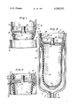
- FIG. 1 is a fragmentary vertical sectional view through the components of the device following an initial assembly step
- FIG. 2 is a vertical sectional view of the accumulator device at a further step of its formation
- FIG. 3 is a view similar to FIG. 1 showing the parts in their final disposition after assembly has been completed.
- an accumulator device comprising a pressure vessel 10, the lower end 11 of which is generally hemispherical and includes an oil port 12 preferably having a beveled valve seat 13 formed at the junction with the oil port.
- Means, such as an internal threaded area 14, may be provided to effect connection of the oil port with a hydraulic system.
- the uppermost end 15 of the pressure vessel defines an open mouth portion.
- the device includes a bladder subassembly 16 including a generally cylindrical metallic skirt 17, the lowermost or bladder retainer portion 18 of which is inturned to provide an annular anchoring area for the thickened rim portion 19 of a bladder member 20.
- the bladder member 20, which is made of a distensible elastomeric material preferably includes a button or valve 20' at its lower end.
- the thickened rim portion 19 of the bladder may be bonded to or molded insitu over the portion 18 of the bladder retainer skirt 17.
- a cap member 21 is provided, which cap member defines the uppermost wall of the accumulator device.
- the cap member may include a gas charging valve assembly, shown diagrammatically at 22, extending through the circular wall 23 of the cap.
- the cap assembly 21 includes a cylindrical, outwardly directed short skirt portion 24, the outer circumference of which forms an intimate fit with the inner circumference of the bladder retainer ring or skirt 17.
- the cap member 21 is sleeved inwardly into the ring or skirt 17 and an annular resistance weld 25 is formed between the juxtaposed skirts 17 and 24.
- the method of forming a resistance weld is essentially conventional, involving pressing the opposed electrodes against the opposite faces of the members 17 and 24 while progressively relatively rotating the side members in the noted contact with the electrodes while passing a welding current between the electrodes.
- annular weld 25 provides an effective gas-tight seal between the ring 17 and the skirt 24.
- FIG. 1 discloses the components after formation of the weld 25.
- the next step in assembly involves advancing the bladder subassembly and attached cap 21 into the interior of the pressure vessel through the open mouth portion 15.
- the external circumference of the ring 17 closely interfits with the circumference of the internal diameter of the pressure vessel 10.
- Axial movement of the ring 17 is effected until the outer edge portion 26 is in alignment with the open mouth or end portion 15 of the pressure vessel. Thereafter, a second annular weld 27 is effected, as previously described, between the pressure vessel and the ring 17, such weld providing a dependable seal against the escape of oil between the superimposed parts.
- weld 27 similarly forms an effective seal against the leakage of oil.
- weld 27 is effected after the bladder is positioned within the pressure vessel, the weld is formed in such manner that both connected surfaces are likewise exposed to the atmosphere for efficient cooling. Additionally, the weld 27 is formed at a position further from the bladder than the weld 25, providing additional assurance against damage to the bladder.
Abstract
Description
Claims (4)
Priority Applications (14)
| Application Number | Priority Date | Filing Date | Title |
|---|---|---|---|
| US06/093,041 US4280533A (en) | 1979-11-13 | 1979-11-13 | Low pressure, low cost accumulator |
| CA352,919A CA1123312A (en) | 1979-11-13 | 1980-05-28 | Low pressure, low cost accumulator and method of making the same |
| JP10104580A JPS5670101A (en) | 1979-11-13 | 1980-07-23 | Accumulator device and production thereof |
| FR8023813A FR2469585A1 (en) | 1979-11-13 | 1980-11-07 | PRESSURE TANK AND MANUFACTURING METHOD THEREOF |
| GB8036092A GB2062761A (en) | 1979-11-13 | 1980-11-10 | Pressure vessel assemblies |
| CH839780A CH638872A5 (en) | 1979-11-13 | 1980-11-12 | PRESSURE ACCUMULATOR AND MANUFACTURING METHOD THEREOF. |
| SE8007937A SE448393B (en) | 1979-11-13 | 1980-11-12 | ACCUMULATOR DEVICE AND WAY TO MANUFACTURE IT |
| NL8006175A NL8006175A (en) | 1979-11-13 | 1980-11-12 | ACCUMULATOR AND METHOD FOR MANUFACTURING THAT. |
| DE19803042641 DE3042641A1 (en) | 1979-11-13 | 1980-11-12 | HYDRO STORAGE AND METHOD FOR THE PRODUCTION THEREOF |
| BE0/202769A BE886119A (en) | 1979-11-13 | 1980-11-12 | PRESSURE TANK AND MANUFACTURING METHOD THEREOF |
| IT25943/80A IT1134250B (en) | 1979-11-13 | 1980-11-13 | LOW COST LOW PRESSURE ACCUMULATOR AND METHOD FOR ITS MANUFACTURE |
| AU64346/80A AU545985B2 (en) | 1979-11-13 | 1980-11-13 | Accumulator vessel |
| US06/248,858 US4352231A (en) | 1979-11-13 | 1981-03-30 | Method of forming a low pressure low cost accumulator |
| US06/332,456 US4427028A (en) | 1979-11-13 | 1981-12-21 | Resistance welded accumulator device |
Applications Claiming Priority (1)
| Application Number | Priority Date | Filing Date | Title |
|---|---|---|---|
| US06/093,041 US4280533A (en) | 1979-11-13 | 1979-11-13 | Low pressure, low cost accumulator |
Related Child Applications (2)
| Application Number | Title | Priority Date | Filing Date |
|---|---|---|---|
| US06/248,858 Division US4352231A (en) | 1979-11-13 | 1981-03-30 | Method of forming a low pressure low cost accumulator |
| US25083381A Continuation-In-Part | 1979-11-13 | 1981-04-03 |
Publications (1)
| Publication Number | Publication Date |
|---|---|
| US4280533A true US4280533A (en) | 1981-07-28 |
Family
ID=22236560
Family Applications (1)
| Application Number | Title | Priority Date | Filing Date |
|---|---|---|---|
| US06/093,041 Expired - Lifetime US4280533A (en) | 1979-11-13 | 1979-11-13 | Low pressure, low cost accumulator |
Country Status (12)
| Country | Link |
|---|---|
| US (1) | US4280533A (en) |
| JP (1) | JPS5670101A (en) |
| AU (1) | AU545985B2 (en) |
| BE (1) | BE886119A (en) |
| CA (1) | CA1123312A (en) |
| CH (1) | CH638872A5 (en) |
| DE (1) | DE3042641A1 (en) |
| FR (1) | FR2469585A1 (en) |
| GB (1) | GB2062761A (en) |
| IT (1) | IT1134250B (en) |
| NL (1) | NL8006175A (en) |
| SE (1) | SE448393B (en) |
Cited By (5)
| Publication number | Priority date | Publication date | Assignee | Title |
|---|---|---|---|---|
| US4413653A (en) * | 1981-10-08 | 1983-11-08 | Halliburton Company | Inflation anchor |
| US5560513A (en) * | 1995-12-26 | 1996-10-01 | Jarrell; Teddy W. | Spill-proof drink container assembly |
| EP1106277A2 (en) * | 1999-12-01 | 2001-06-13 | MAN Nutzfahrzeuge Aktiengesellschaft | Method of making a compressed-air vessel |
| US20050171477A1 (en) * | 2002-05-23 | 2005-08-04 | Seedlings Life Science Ventures | Apparatus and method for rapid auto-injection of medication |
| US20120037253A1 (en) * | 2009-05-15 | 2012-02-16 | Norbert Weber | Hydraulic accumulator |
Families Citing this family (1)
| Publication number | Priority date | Publication date | Assignee | Title |
|---|---|---|---|---|
| UA119134C2 (en) | 2012-08-08 | 2019-05-10 | Аарон Фьюстел | Rotary expansible chamber devices having adjustable working-fluid ports, and systems incorporating the same |
Citations (5)
| Publication number | Priority date | Publication date | Assignee | Title |
|---|---|---|---|---|
| US3420273A (en) * | 1965-11-30 | 1969-01-07 | Greer Hydraulics Inc | Pressure accumulator |
| US3494378A (en) * | 1966-11-17 | 1970-02-10 | Greer Hydraulics Inc | Pressure vessels |
| US3500866A (en) * | 1967-08-01 | 1970-03-17 | Greer Hydraulics Inc | Pressure vessel |
| US4010773A (en) * | 1973-05-22 | 1977-03-08 | Daimler-Benz Aktiengesellschaft | Hydropneumatic pressure storage device |
| US4045861A (en) * | 1975-02-24 | 1977-09-06 | Greer Hydraulics, Inc. | Method of forming a pressure accumulator |
Family Cites Families (4)
| Publication number | Priority date | Publication date | Assignee | Title |
|---|---|---|---|---|
| US3690347A (en) * | 1970-12-16 | 1972-09-12 | Greer Hydraulics Inc | Pressure vessel |
| US3881519A (en) * | 1973-04-23 | 1975-05-06 | Greer Hydraulics Inc | Pressure vessel |
| US3847182A (en) * | 1973-06-18 | 1974-11-12 | E Greer | Hydro-pneumatic flexible bladder accumulator |
| US3907000A (en) * | 1974-04-25 | 1975-09-23 | Teledyne Sprague Eng | Hydro-pneumatic flexible bladder accumulator |
-
1979
- 1979-11-13 US US06/093,041 patent/US4280533A/en not_active Expired - Lifetime
-
1980
- 1980-05-28 CA CA352,919A patent/CA1123312A/en not_active Expired
- 1980-07-23 JP JP10104580A patent/JPS5670101A/en active Pending
- 1980-11-07 FR FR8023813A patent/FR2469585A1/en active Granted
- 1980-11-10 GB GB8036092A patent/GB2062761A/en not_active Withdrawn
- 1980-11-12 BE BE0/202769A patent/BE886119A/en not_active IP Right Cessation
- 1980-11-12 DE DE19803042641 patent/DE3042641A1/en not_active Ceased
- 1980-11-12 CH CH839780A patent/CH638872A5/en not_active IP Right Cessation
- 1980-11-12 NL NL8006175A patent/NL8006175A/en not_active Application Discontinuation
- 1980-11-12 SE SE8007937A patent/SE448393B/en not_active IP Right Cessation
- 1980-11-13 AU AU64346/80A patent/AU545985B2/en not_active Ceased
- 1980-11-13 IT IT25943/80A patent/IT1134250B/en active
Patent Citations (5)
| Publication number | Priority date | Publication date | Assignee | Title |
|---|---|---|---|---|
| US3420273A (en) * | 1965-11-30 | 1969-01-07 | Greer Hydraulics Inc | Pressure accumulator |
| US3494378A (en) * | 1966-11-17 | 1970-02-10 | Greer Hydraulics Inc | Pressure vessels |
| US3500866A (en) * | 1967-08-01 | 1970-03-17 | Greer Hydraulics Inc | Pressure vessel |
| US4010773A (en) * | 1973-05-22 | 1977-03-08 | Daimler-Benz Aktiengesellschaft | Hydropneumatic pressure storage device |
| US4045861A (en) * | 1975-02-24 | 1977-09-06 | Greer Hydraulics, Inc. | Method of forming a pressure accumulator |
Cited By (7)
| Publication number | Priority date | Publication date | Assignee | Title |
|---|---|---|---|---|
| US4413653A (en) * | 1981-10-08 | 1983-11-08 | Halliburton Company | Inflation anchor |
| US5560513A (en) * | 1995-12-26 | 1996-10-01 | Jarrell; Teddy W. | Spill-proof drink container assembly |
| EP1106277A2 (en) * | 1999-12-01 | 2001-06-13 | MAN Nutzfahrzeuge Aktiengesellschaft | Method of making a compressed-air vessel |
| EP1106277A3 (en) * | 1999-12-01 | 2002-12-18 | MAN Nutzfahrzeuge Aktiengesellschaft | Method of making a compressed-air vessel |
| US20050171477A1 (en) * | 2002-05-23 | 2005-08-04 | Seedlings Life Science Ventures | Apparatus and method for rapid auto-injection of medication |
| US20120037253A1 (en) * | 2009-05-15 | 2012-02-16 | Norbert Weber | Hydraulic accumulator |
| US8746286B2 (en) * | 2009-05-15 | 2014-06-10 | Hydac Tehnology GmbH | Hydraulic accumulator |
Also Published As
| Publication number | Publication date |
|---|---|
| SE448393B (en) | 1987-02-16 |
| AU6434680A (en) | 1981-05-21 |
| FR2469585B1 (en) | 1985-02-15 |
| BE886119A (en) | 1981-03-02 |
| DE3042641A1 (en) | 1981-05-21 |
| SE8007937L (en) | 1981-05-14 |
| IT1134250B (en) | 1986-08-13 |
| NL8006175A (en) | 1981-06-01 |
| IT8025943A0 (en) | 1980-11-13 |
| CA1123312A (en) | 1982-05-11 |
| GB2062761A (en) | 1981-05-28 |
| CH638872A5 (en) | 1983-10-14 |
| AU545985B2 (en) | 1985-08-08 |
| FR2469585A1 (en) | 1981-05-22 |
| JPS5670101A (en) | 1981-06-11 |
Similar Documents
| Publication | Publication Date | Title |
|---|---|---|
| US4448217A (en) | Accumulator having bladder in expansion limiting contact with casing | |
| US3674054A (en) | Pressure vessel | |
| US4280533A (en) | Low pressure, low cost accumulator | |
| US3500866A (en) | Pressure vessel | |
| US4352231A (en) | Method of forming a low pressure low cost accumulator | |
| CN102428283A (en) | Hydraulic accumulator | |
| US4288894A (en) | Method of manufacturing pressure vessels by heat forming | |
| US4425698A (en) | Method of assembling a pressure vessel | |
| US4098297A (en) | Pressure accumulator and method of forming the same | |
| US4192350A (en) | Pressure vessel | |
| US4427028A (en) | Resistance welded accumulator device | |
| US4113006A (en) | Two-piece tube plug for repairing tubes in heat exchangers and the like | |
| US2779095A (en) | Method of making a bellows assembly | |
| US5453195A (en) | High strength filter | |
| US4045861A (en) | Method of forming a pressure accumulator | |
| CA1138301A (en) | Low cost accumulator device | |
| US3690347A (en) | Pressure vessel | |
| US4177836A (en) | Disposable pressure vessel | |
| US4429718A (en) | Pressure resistant accumulator device | |
| JPS628401Y2 (en) | ||
| US4852615A (en) | Hydropneumatic accumulator | |
| US4328836A (en) | Pressure vessel | |
| JPS5921334Y2 (en) | safety valve | |
| JP3818353B2 (en) | accumulator | |
| WO1996005493A1 (en) | Explosion welded transition joint for a pressure transmitter |
Legal Events
| Date | Code | Title | Description |
|---|---|---|---|
| STCF | Information on status: patent grant |
Free format text: PATENTED CASE |
|
| AS | Assignment |
Owner name: GREER HYDRAULICS, INCORPORATED Free format text: CHANGE OF NAME;ASSIGNOR:LIQUIDONICS INDUSTRIES, INC.,;REEL/FRAME:003855/0836 Effective date: 19791203 Owner name: GREER HYDRAULICS, INCORPORATED, STATELESS Free format text: CHANGE OF NAME;ASSIGNOR:LIQUIDONICS INDUSTRIES, INC.,;REEL/FRAME:003855/0836 Effective date: 19791203 |
|
| AS | Assignment |
Owner name: GREE HYDRAULICS OF CALIFORNIA, INC., A CORP. OF CA Free format text: MERGER;ASSIGNOR:GREER HYDRAULICS, INCORPORATED, GREER HYDRAULICS OF CALIFORNIA, INC.;REEL/FRAME:004014/0964 Effective date: 19811218 |
|
| AS | Assignment |
Owner name: VSI CORPORATION Free format text: MERGER;ASSIGNOR:GREER HYDRAULICS, INCORPORATED;REEL/FRAME:004013/0645 Effective date: 19820204 |
|
| AS | Assignment |
Owner name: FIGGIE INTERNATIONAL INC., 1000 VIRGINIA CENTER PA Free format text: ASSIGNMENT OF ASSIGNORS INTEREST.;ASSIGNOR:VSI CORPORATION;REEL/FRAME:004822/0665 Effective date: 19871218 Owner name: FIGGIE INTERNATIONAL INC., A CORP. OF DE,VIRGINIA Free format text: ASSIGNMENT OF ASSIGNORS INTEREST;ASSIGNOR:VSI CORPORATION;REEL/FRAME:004822/0665 Effective date: 19871218 |
|
| AS | Assignment |
Owner name: S-P MANUFACTURING CORPORATION, THE, A CORP. OF OHI Free format text: ASSIGNMENT OF ASSIGNORS INTEREST.;ASSIGNOR:FIGGIE INTERNATIONAL INC.;REEL/FRAME:005017/0972 Effective date: 19890106 |
|
| AS | Assignment |
Owner name: FIRST NATIONAL BANK OF BOSTON, AS COLLATERAL AGENT Free format text: SECURITY INTEREST;ASSIGNOR:FIGGIE INTERNATIONAL INC. A DE CORP.;REEL/FRAME:007072/0851 Effective date: 19940630 |
|
| AS | Assignment |
Owner name: FIGGIE INTERNATIONAL INC. Free format text: ASSIGNMENT OF ASSIGNORS INTEREST;ASSIGNOR:SP/SHEFFER INTERNATIONAL INC.;REEL/FRAME:007403/0237 Effective date: 19940908 Owner name: SP/SHEFFER INTERNATIONAL INC., OHIO Free format text: CHANGE OF NAME;ASSIGNOR:S-P MANUFACTURING CORPORATION, THE;REEL/FRAME:007372/0398 Effective date: 19911215 |
|
| AS | Assignment |
Owner name: FIGGIE INTERNATIONAL INC., OHIO Free format text: RELEASE OF SECURITY INTEREST;ASSIGNOR:FIRST NATIONAL BANK OF BOSTON, THE;REEL/FRAME:007435/0396 Effective date: 19950329 |