US4261501A - Laminated insulated hot drink cup - Google Patents
Laminated insulated hot drink cup Download PDFInfo
- Publication number
- US4261501A US4261501A US06/089,762 US8976279A US4261501A US 4261501 A US4261501 A US 4261501A US 8976279 A US8976279 A US 8976279A US 4261501 A US4261501 A US 4261501A
- Authority
- US
- United States
- Prior art keywords
- sidewall
- cup
- overwrap
- major surface
- set forth
- Prior art date
- Legal status (The legal status is an assumption and is not a legal conclusion. Google has not performed a legal analysis and makes no representation as to the accuracy of the status listed.)
- Expired - Lifetime
Links
Images
Classifications
-
- B—PERFORMING OPERATIONS; TRANSPORTING
- B65—CONVEYING; PACKING; STORING; HANDLING THIN OR FILAMENTARY MATERIAL
- B65D—CONTAINERS FOR STORAGE OR TRANSPORT OF ARTICLES OR MATERIALS, e.g. BAGS, BARRELS, BOTTLES, BOXES, CANS, CARTONS, CRATES, DRUMS, JARS, TANKS, HOPPERS, FORWARDING CONTAINERS; ACCESSORIES, CLOSURES, OR FITTINGS THEREFOR; PACKAGING ELEMENTS; PACKAGES
- B65D81/00—Containers, packaging elements, or packages, for contents presenting particular transport or storage problems, or adapted to be used for non-packaging purposes after removal of contents
- B65D81/38—Containers, packaging elements, or packages, for contents presenting particular transport or storage problems, or adapted to be used for non-packaging purposes after removal of contents with thermal insulation
- B65D81/3876—Containers, packaging elements, or packages, for contents presenting particular transport or storage problems, or adapted to be used for non-packaging purposes after removal of contents with thermal insulation insulating sleeves or jackets for cans, bottles, barrels, etc.
-
- B—PERFORMING OPERATIONS; TRANSPORTING
- B65—CONVEYING; PACKING; STORING; HANDLING THIN OR FILAMENTARY MATERIAL
- B65D—CONTAINERS FOR STORAGE OR TRANSPORT OF ARTICLES OR MATERIALS, e.g. BAGS, BARRELS, BOTTLES, BOXES, CANS, CARTONS, CRATES, DRUMS, JARS, TANKS, HOPPERS, FORWARDING CONTAINERS; ACCESSORIES, CLOSURES, OR FITTINGS THEREFOR; PACKAGING ELEMENTS; PACKAGES
- B65D1/00—Containers having bodies formed in one piece, e.g. by casting metallic material, by moulding plastics, by blowing vitreous material, by throwing ceramic material, by moulding pulped fibrous material, by deep-drawing operations performed on sheet material
- B65D1/22—Boxes or like containers with side walls of substantial depth for enclosing contents
- B65D1/26—Thin-walled containers, e.g. formed by deep-drawing operations
- B65D1/265—Drinking cups
-
- Y—GENERAL TAGGING OF NEW TECHNOLOGICAL DEVELOPMENTS; GENERAL TAGGING OF CROSS-SECTIONAL TECHNOLOGIES SPANNING OVER SEVERAL SECTIONS OF THE IPC; TECHNICAL SUBJECTS COVERED BY FORMER USPC CROSS-REFERENCE ART COLLECTIONS [XRACs] AND DIGESTS
- Y10—TECHNICAL SUBJECTS COVERED BY FORMER USPC
- Y10S—TECHNICAL SUBJECTS COVERED BY FORMER USPC CROSS-REFERENCE ART COLLECTIONS [XRACs] AND DIGESTS
- Y10S220/00—Receptacles
- Y10S220/918—Spacing element for separating the walls of a spaced-wall container
Definitions
- the present invention is concerned with an improved, decorative cup especially adapted for use in drinking of hot liquids such as coffee or tea without causing discomfort to or injuring the hands of the user by virtue of heat transmitted from the hot liquid through the cup sidewall. More particularly, it is concerned with such an improved cup which is characterized by a series of elongated, side-by-side, discrete dead air cells in the sidewall thereof for thermal insulation purposes.
- Disposable paper or synthetic resin drinking cups are of course extremely common. Simple paper cups are quite acceptable for holding cold or lukewarm beverages, but they present problems when used for hot drinks such as coffee or tea, which may be 170-175° F. in temperature. In such cases the user tends to grasp the cup between thumb and forefinger at the upper and lower extremities of the cup, so as to avoid grasping the cup sidewall. While this alleviates the problem to some extent, it is extremely awkward and may result in spillage of the hot liquid onto the user.
- Another type of hot drink cup in widespread use is formed of a foamed synthetic resin material.
- foamed synthetic resin material Such cups have excellent thermal insulation characteristics and adequately protect the hands of a user even when an extremely hot beverage is being drunk.
- the foamed cups cannot generally be provided with matched sets of party goods, inasmuch as such sets must include decorative hot drink cups.
- the preferred hot drink cup of the invention broadly includes a synthetic resin cup member having a decorative, paper overwrap permanently disposed about the sidewall thereof in order to create a laminated unit.
- the cup also includes structure defining a series of elongated, upright, discrete, dead air chambers or cells between the synthetic resin sidewall and overwrap, so as to give desirable insulative qualities.
- the synthetic resin cup member includes, on the exterior face thereof, a pair of annular, continuous bands extending about the member sidewall and located adjacent the upper and lower extremities thereof.
- the bands are spaced outwardly a short distance from the major surface of the sidewall, and are adapted to engage the corresponding margins of the paper overwrap.
- a series of elongated, spaced, juxtaposed spacer ribs are further provided on the exterior face of the cup member sidewall and present, on the outermost extremities thereof, respective, relatively sharp pointed contact lines.
- the overwrap is adhesively secured to the spaced, annular bands, and is in contact with the respective, longituidinally extending, sharp contact lines. In this fashion thermal contact between the synthetic resin sidewall of the cup member and the overwrap is minimized.
- the preferred cup of the invention also includes an uppermost, circumferential, circular bead which extends outwardly and engages the upper margin of the paper overwrap for preventing passage of liquid between the cup member sidewall and overwrap.
- an uppermost, circumferential, circular bead which extends outwardly and engages the upper margin of the paper overwrap for preventing passage of liquid between the cup member sidewall and overwrap.
- a series of spaced, circularly arranged, upstanding nibs are formed at the junction between the sidewall and bottom wall of the cup member, in order to facilitate the separation of a series of nested cups.
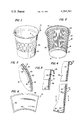
- FIG. 1 is a perspective view of a completed hot drink cup in accordance with the invention
- FIG. 2 is a perspective view of a synthetic resin cup member forming a part of the overall cup of the invention
- FIG. 3 is a fragmentary vertical sectional view illustrating the orientation of the paper overwrap relative to the cup member sidewall and prior to the formation of the circumferential bead;
- FIG. 4 is a view similar to that of FIG. 3, but showing the complete cup having an uppermost circumferential bead;
- FIG. 5 is a sectional view taken along line 5--5 of FIG. 4 which further illustrates the sidewall construction of the overall cup.
- FIG. 6 is an elevational view of an overwrap to be applied to the sidewall of a cup member in accordance with the invention.
- a hot drink cup 10 in accordance with the invention is illustrated perspectively in FIG. 1 and broadly includes an inner, liquid-holding synthetic resin cup member 12 and an outer, decorated paper overwrap 14 applied to the sidewall of the cup member 12.
- cup member 12 is an integral unit preferably formed of impact grade polystyrene material having an izod impact strength of from about 0.5 to 1.5.
- the member 12 includes a circular, concaval-convex bottom wall 16 and an upwardly extending, generally frustoconical sidewall 18.
- the sidewall 18 is formed to present a circular in cross section major surface 20 which is bounded at top and bottom by respective annular bands 22, 24.
- the bands are spaced outwardly a short distance (from about 0.012 to 0.025 inches, most preferably about 0.018 inches) from the major surface 20.
- annular band 24 directly connects to bottom wall 16, whereas the uppermost end of the band 22 merges into a circumferential bead-forming lip section 26 (see Fig. 3).
- the exterior surface of the sidewall 18 is further provided with a series of elongated, spaced, longitudinally extending, side-by-side spacer ribs 28 which are equally circumferentially spaced about the sidewall 18.
- the ribs 28 merge into and are connected to the annular bands 22, 24, as best seen in FIG. 2, and moreover extend outwardly from the major surface 20 a distance equal to the distance of the bands 22, 24 from the major surface 20.
- each of the ribs 28 is substantially triangular in cross section, and presents, at the outermost extremity thereof, a relatively sharp pointed contact line 30.
- a series of circumferentially spaced, upstanding, block-like projections or nibs 32 are formed in the cup member 12 at the point of interconnection between bottom wall 16 and sidewall 18.
- the purpose of the nibs 32 is to facilitate one-by-one detachment of cups from a nested stack thereof.
- Overwrap 14 is formed of conventional die cut paper stock and normallly is provided with a printed decoration 34 on the outer surface thereof.
- the overwrap 14 is sized to wrap about and engage the outermost surface of the sidewall 18 as will be explained; furthermore, the inner face of the overwrap 14 may be provided with three glue lines 36, 38 and 40 for the purpose of securely connecting the overwrap to the sidewall 18 of cup member 12.
- overwrap 14 is in direct, adhesive contact with the annular bands 22, 24 (adhesive strip 36 being secured to the upper band 22, whereas adhesive strip 40 connects to the lower band 24).
- the outermost contact lines 30 of the ribs 28 are in essentially line contact with the paper overwrap 40. This is important inasmuch as only minimal thermal contact is thus established between the sidewall 18 of cup member 12, and the overwrap 14.
- the finished cup 10 in accordance with the invention includes a circumferential, uppermost bead 42 formed from the section 26 and extending downwardly and turned in for engagement with the upper margin of the overwrap 14.
- a bead is of course known, but it will be observed in this connection that the bead effectively presents a seal which precludes the passage of liquid between the sidewall 18 and overwrap 14.
- cup member 12 When a polystyrene material of the type described above is used for the formation of cup member 12, it has been found that the thickness thereof should be from about 0.015 to 0.020 inches. In this fashion adequate strength is imparted to the cup member, without wastage of material. Furthermore, spacer ribs 28 are advantageously formed to present an included angle of about 60° at their apices, and with the sharpest contact line presently available through a molding process, i.e., about a 0.005 inch radius.
- the paper employed for the liner 14 is preferably 11 point stock (0.011 inches in thickness) clay coated bleached paper; such has been found advantageous for printing purposes and is also relatively opaque and has sufficient strength for normal handling.
- the overwrap 14 may be wrapped about the sidewall 18 of cup member 12, and a permanent connection effected by means of the glue lines 36, 38 and 40.
- a preprinted, die cut blank can be wrapped about an appropriately shaped mandrel with the overlapping edges thereof glued so as to present a frustoconical sleeve.
- Respective strips of adhesive material can then be placed around the bands 22, 24 of the cup member 12, whereupon the latter can be inserted into the frustoconical sleeve with the uppermost margin of the latter coming into close proximity with the outwardly extending circumferential lip-forming portion 26 (see FIG. 3).
- the final step of cup manufacture involves formation of the bead 42. This is accomplished by heating the section 26 to soften the polystyrene material, and a finished bead 42 is formed about the uppermost margin of the cup in the manner illustrated in FIG. 4.
- the thermal insulating qualities of the laminated cup hereof are substantially equal to that of known foamed synthetic resin cups.
- the cups of the invention can be provided with virtually any surface decoration, so that they can be used in matched party sets or the like.
Abstract
An insulated, decorative hot drink cup for hot coffee or the like is provided which can be grasped and drunk from without fear that the user's fingers will be burned. The cup includes an inner, integral, synthetic resin cup member having a series of spaced, exterior, longitudinally extending, triangular in cross section ribs on the sidewall thereof, and an outer decorative paper overwrap permanently applied over and in contact with the ribs. This structure defines a series of discrete, juxtaposed, dead air chambers or cells in the cup assembly sidewall for maximum heat insulation, and the thermally minimal, essentially line contact between the rib apices and overwrap enhances this effect. An uppermost circumferential bead formed on the cup member provides a further seal and prevents passage of liquid between the overwrap and member sidewall.
Description
1. Field of the Invention
The present invention is concerned with an improved, decorative cup especially adapted for use in drinking of hot liquids such as coffee or tea without causing discomfort to or injuring the hands of the user by virtue of heat transmitted from the hot liquid through the cup sidewall. More particularly, it is concerned with such an improved cup which is characterized by a series of elongated, side-by-side, discrete dead air cells in the sidewall thereof for thermal insulation purposes.
2. Description of the Prior Art
Disposable paper or synthetic resin drinking cups are of course extremely common. Simple paper cups are quite acceptable for holding cold or lukewarm beverages, but they present problems when used for hot drinks such as coffee or tea, which may be 170-175° F. in temperature. In such cases the user tends to grasp the cup between thumb and forefinger at the upper and lower extremities of the cup, so as to avoid grasping the cup sidewall. While this alleviates the problem to some extent, it is extremely awkward and may result in spillage of the hot liquid onto the user.
Another expedient resorted to in the past with paper cups has been the provision of a paper handle secured to the cup sidewall. These handles do provide a means of cup manipulation without directly grasping the cup sidewall; nevertheless, they present significant problems inasmuch as manufacturing costs are increased and because such handles tend to break away from the cup body during use thereof.
Another type of hot drink cup in widespread use is formed of a foamed synthetic resin material. Such cups have excellent thermal insulation characteristics and adequately protect the hands of a user even when an extremely hot beverage is being drunk. However, it is very difficult to decorate such foamed, insulative cups, and for the most part these are simply sold and used in an undecorated condition. Thus, the foamed cups cannot generally be provided with matched sets of party goods, inasmuch as such sets must include decorative hot drink cups.
Accordingly, there is a real need in the art for an insulated hot drink cup which can be provided with high quality, aesthetically pleasing decorations, and which can be used for the drinking of very hot liquids.
The preferred hot drink cup of the invention broadly includes a synthetic resin cup member having a decorative, paper overwrap permanently disposed about the sidewall thereof in order to create a laminated unit. The cup also includes structure defining a series of elongated, upright, discrete, dead air chambers or cells between the synthetic resin sidewall and overwrap, so as to give desirable insulative qualities.
Preferably, the synthetic resin cup member includes, on the exterior face thereof, a pair of annular, continuous bands extending about the member sidewall and located adjacent the upper and lower extremities thereof. The bands are spaced outwardly a short distance from the major surface of the sidewall, and are adapted to engage the corresponding margins of the paper overwrap. A series of elongated, spaced, juxtaposed spacer ribs are further provided on the exterior face of the cup member sidewall and present, on the outermost extremities thereof, respective, relatively sharp pointed contact lines. The overwrap is adhesively secured to the spaced, annular bands, and is in contact with the respective, longituidinally extending, sharp contact lines. In this fashion thermal contact between the synthetic resin sidewall of the cup member and the overwrap is minimized.
The preferred cup of the invention also includes an uppermost, circumferential, circular bead which extends outwardly and engages the upper margin of the paper overwrap for preventing passage of liquid between the cup member sidewall and overwrap. In addition, a series of spaced, circularly arranged, upstanding nibs are formed at the junction between the sidewall and bottom wall of the cup member, in order to facilitate the separation of a series of nested cups.
FIG. 1 is a perspective view of a completed hot drink cup in accordance with the invention;
FIG. 2 is a perspective view of a synthetic resin cup member forming a part of the overall cup of the invention;
FIG. 3 is a fragmentary vertical sectional view illustrating the orientation of the paper overwrap relative to the cup member sidewall and prior to the formation of the circumferential bead;
FIG. 4 is a view similar to that of FIG. 3, but showing the complete cup having an uppermost circumferential bead;
FIG. 5 is a sectional view taken along line 5--5 of FIG. 4 which further illustrates the sidewall construction of the overall cup; and
FIG. 6 is an elevational view of an overwrap to be applied to the sidewall of a cup member in accordance with the invention.
Turning now to the drawing, a hot drink cup 10 in accordance with the invention is illustrated perspectively in FIG. 1 and broadly includes an inner, liquid-holding synthetic resin cup member 12 and an outer, decorated paper overwrap 14 applied to the sidewall of the cup member 12.
In more detail, cup member 12 is an integral unit preferably formed of impact grade polystyrene material having an izod impact strength of from about 0.5 to 1.5. The member 12 includes a circular, concaval-convex bottom wall 16 and an upwardly extending, generally frustoconical sidewall 18. As best seen in FIG. 4, the sidewall 18 is formed to present a circular in cross section major surface 20 which is bounded at top and bottom by respective annular bands 22, 24. The bands are spaced outwardly a short distance (from about 0.012 to 0.025 inches, most preferably about 0.018 inches) from the major surface 20.
The lowermost end of annular band 24 directly connects to bottom wall 16, whereas the uppermost end of the band 22 merges into a circumferential bead-forming lip section 26 (see Fig. 3).
The exterior surface of the sidewall 18 is further provided with a series of elongated, spaced, longitudinally extending, side-by-side spacer ribs 28 which are equally circumferentially spaced about the sidewall 18. The ribs 28 merge into and are connected to the annular bands 22, 24, as best seen in FIG. 2, and moreover extend outwardly from the major surface 20 a distance equal to the distance of the bands 22, 24 from the major surface 20. Referring to FIG. 5, it will be seen that each of the ribs 28 is substantially triangular in cross section, and presents, at the outermost extremity thereof, a relatively sharp pointed contact line 30.
A series of circumferentially spaced, upstanding, block-like projections or nibs 32 are formed in the cup member 12 at the point of interconnection between bottom wall 16 and sidewall 18. The purpose of the nibs 32 is to facilitate one-by-one detachment of cups from a nested stack thereof.
Referring to FIGS. 3 and 4, it will be seen that overwrap 14 is in direct, adhesive contact with the annular bands 22, 24 (adhesive strip 36 being secured to the upper band 22, whereas adhesive strip 40 connects to the lower band 24).
Furthermore, it will be appreciated that the outermost contact lines 30 of the ribs 28 are in essentially line contact with the paper overwrap 40. This is important inasmuch as only minimal thermal contact is thus established between the sidewall 18 of cup member 12, and the overwrap 14.
The finished cup 10 in accordance with the invention includes a circumferential, uppermost bead 42 formed from the section 26 and extending downwardly and turned in for engagement with the upper margin of the overwrap 14. Such a bead is of course known, but it will be observed in this connection that the bead effectively presents a seal which precludes the passage of liquid between the sidewall 18 and overwrap 14.
When a polystyrene material of the type described above is used for the formation of cup member 12, it has been found that the thickness thereof should be from about 0.015 to 0.020 inches. In this fashion adequate strength is imparted to the cup member, without wastage of material. Furthermore, spacer ribs 28 are advantageously formed to present an included angle of about 60° at their apices, and with the sharpest contact line presently available through a molding process, i.e., about a 0.005 inch radius.
The paper employed for the liner 14 is preferably 11 point stock (0.011 inches in thickness) clay coated bleached paper; such has been found advantageous for printing purposes and is also relatively opaque and has sufficient strength for normal handling.
In constructing the cup 10 of the invention, the overwrap 14 may be wrapped about the sidewall 18 of cup member 12, and a permanent connection effected by means of the glue lines 36, 38 and 40. Optionally, a preprinted, die cut blank can be wrapped about an appropriately shaped mandrel with the overlapping edges thereof glued so as to present a frustoconical sleeve. Respective strips of adhesive material can then be placed around the bands 22, 24 of the cup member 12, whereupon the latter can be inserted into the frustoconical sleeve with the uppermost margin of the latter coming into close proximity with the outwardly extending circumferential lip-forming portion 26 (see FIG. 3).
The final step of cup manufacture involves formation of the bead 42. This is accomplished by heating the section 26 to soften the polystyrene material, and a finished bead 42 is formed about the uppermost margin of the cup in the manner illustrated in FIG. 4.
Actual thermal tests of a cup 10 in accordance with the invention have demonstrated that the thermal insulating qualities of the laminated cup hereof are substantially equal to that of known foamed synthetic resin cups. At the same time, the cups of the invention can be provided with virtually any surface decoration, so that they can be used in matched party sets or the like.
Claims (9)
1. A hot drink cup, comprising:
a cup member formed of synthetic resin material and having a bottom wall and an upwardly extending, continuous sidewall connected to the bottom wall for cooperatively presenting a liquid-holding cavity;
said sidewall including structure which defines, on the exterior face thereof,
(1) a pair of annular, continuous bands respectively extending about said sidewall, being located adjacent the upper and lower extremities of said sidewall, and spaced outwardly from the major surface presented by said sidewall; and
(2) a series of elongated, spaced, side-by-side spacer ribs disposed in an upright relation, extending between said bands and outwardly from said major surface, and presenting, on the outermost extremities thereof, respective, relatively sharp, pointed contact lines; and
an overlap disposed about said sidewall, and in engagement with said bands and contact lines,
said ribs, member sidewall and overwrap cooperatively defining a series of elongated, discrete dead air cells for creating a heat insulation barrier between hot liquid in said cavity and a person's hand in engagement with the exterior surface of said overlay.
2. The cup as set forth in claim 1 including a circular bead formed at the upper end of said member sidewall which extends outwardly and engages the upper margin of said overwrap.
3. The cup as set forth in claim 1 wherein said overwrap is adhesively secured to said bands.
4. The cup as set forth in claim 1 wherein said cup member is formed of impact grade polystyrene having an izod impact strength of from about 0.5 to 1.5.
5. The cup as set forth in claim 4 wherein said major surface of said member sidewall has a thickness of from about 0.015 to 0.020 inches.
6. The cup as set forth in claim 1 wherein said bands are spaced a distance of from about 0.012 to 0.025 inches from said major surface.
7. The cup as set forth in claim 1 wherein said ribs extend outwardly from said major surface a distance equal to the distance of said bands from said major surface.
8. The cup as set forth in claim 1 wherein said ribs are of triangular cross-section.
9. A hot drink cup, comprising:
a cup member formed of synthetic resin material and having a bottom wall and an upwardly extending, continuous sidewall connected to the bottom wall for cooperatively presenting a liquid-holding cavity;
said sidewall including structure which defines, on the exterior face thereof,
(1) an annular, continuous band extending about said sidewall, located adjacent the upper extremity of said sidewall, and spaced outwardly from the major surface presented by said sidewall; and
(2) a series of elongated, spaced, side-by-side spacer ribs disposed in an upright relation, extending from said band and outwardly from said major surface, and presenting, on the outermost extremities thereof, respective, relatively sharp, pointed contact lines; and
an overlap disposed about said sidewall and in engagement with said band and contact lines.
Priority Applications (1)
| Application Number | Priority Date | Filing Date | Title |
|---|---|---|---|
| US06/089,762 US4261501A (en) | 1979-10-31 | 1979-10-31 | Laminated insulated hot drink cup |
Applications Claiming Priority (1)
| Application Number | Priority Date | Filing Date | Title |
|---|---|---|---|
| US06/089,762 US4261501A (en) | 1979-10-31 | 1979-10-31 | Laminated insulated hot drink cup |
Publications (1)
| Publication Number | Publication Date |
|---|---|
| US4261501A true US4261501A (en) | 1981-04-14 |
Family
ID=22219463
Family Applications (1)
| Application Number | Title | Priority Date | Filing Date |
|---|---|---|---|
| US06/089,762 Expired - Lifetime US4261501A (en) | 1979-10-31 | 1979-10-31 | Laminated insulated hot drink cup |
Country Status (1)
| Country | Link |
|---|---|
| US (1) | US4261501A (en) |
Cited By (88)
| Publication number | Priority date | Publication date | Assignee | Title |
|---|---|---|---|---|
| US4380188A (en) * | 1981-01-28 | 1983-04-19 | Barber-Colman Company | Heat-retarding air distribution unit |
| US4439403A (en) * | 1980-03-08 | 1984-03-27 | Herbert Brunner | Apparatus for conditioning bioinjurious waste |
| US4872569A (en) * | 1984-01-31 | 1989-10-10 | Brown Bolte | Drinking vessels |
| US4927050A (en) * | 1985-09-12 | 1990-05-22 | Palazzo David T | Method of making double wall storage tank for liquids from a metal tank having a patterned surface |
| EP0371918A1 (en) * | 1988-11-29 | 1990-06-06 | Rundpack Ag | Container |
| US5071060A (en) * | 1991-03-29 | 1991-12-10 | Defelice Amedio | Plastic tumbler |
| US5326019A (en) * | 1993-05-03 | 1994-07-05 | Wolff Steven K | Double walled paper cup |
| US5363982A (en) * | 1994-03-07 | 1994-11-15 | Sadlier Claus E | Multi-layered insulated cup formed of one continuous sheet |
| US5415339A (en) * | 1993-04-21 | 1995-05-16 | Howard; Jeremy C. | Drinking cup with open ribbed sidewall |
| US5460323A (en) * | 1995-01-10 | 1995-10-24 | California Environmental Cup, Inc. | Disposable insulated container |
| US5524817A (en) * | 1995-04-04 | 1996-06-11 | Paper Machinery Corporation | Dual walled container |
| US5660326A (en) * | 1995-08-18 | 1997-08-26 | Sherwood Tool Incorporated | Multi-layered insulated cup formed from folded sheet |
| US5713512A (en) * | 1996-09-03 | 1998-02-03 | Polytainers, Inc. | Polymeric insulated container |
| US5746372A (en) * | 1996-12-12 | 1998-05-05 | American Excelsior Company | Biodegradable cup holder |
| US5820016A (en) * | 1996-05-13 | 1998-10-13 | Dunkin' Donuts Incorporated | Cup and lid |
| US5975336A (en) * | 1998-02-13 | 1999-11-02 | Hart; David Alan | Containing device with removable thermal insulating layer |
| USD427009S (en) * | 1992-01-24 | 2000-06-27 | Ekco Housewares, Inc. | Baking pan |
| US6152363A (en) * | 1999-05-03 | 2000-11-28 | Westvaco Corporation | Sleeve construction for improved paperboard cup insulation |
| US20020144769A1 (en) * | 2001-04-05 | 2002-10-10 | Debraal John Charles | Insulated beverage or food container |
| US6536657B2 (en) * | 2001-07-20 | 2003-03-25 | Fort James Corporation | Disposable thermally insulated cup and method for manufacturing the same |
| US6598786B1 (en) * | 2002-03-05 | 2003-07-29 | Tzer-Huang Guo | Melioration of insulating paper container |
| US20030186605A1 (en) * | 1997-03-26 | 2003-10-02 | Fort James Corporation | Insulating stock material and containers and methods of making the same |
| US6655159B1 (en) * | 2002-08-16 | 2003-12-02 | Delphi Technologies, Inc. | Accumulator dehydrator assembly |
| US20040251262A1 (en) * | 2003-06-11 | 2004-12-16 | Laurent Hechmati | Foldable air insulating sleeve |
| US20050006449A1 (en) * | 2003-07-10 | 2005-01-13 | D'amato Gianfranco | Container |
| US20050029337A1 (en) * | 2001-07-20 | 2005-02-10 | Fort James Corporation | Liquid container with uninterrupted comfort band and method of forming same |
| US20050029273A1 (en) * | 2003-06-11 | 2005-02-10 | Laurent Hechmati | Foldable air insulating sleeve |
| US20050115975A1 (en) * | 2003-11-26 | 2005-06-02 | Smith Stephen A. | Two-piece insulated cup |
| US20050189361A1 (en) * | 2004-02-17 | 2005-09-01 | Wincup Holdings, Inc. | Beverage cup for placement in holder |
| US20060076395A1 (en) * | 2004-10-12 | 2006-04-13 | Hayes Thomas J | Container having textured grip and enhanced wall integrity |
| US20060095151A1 (en) * | 2004-11-02 | 2006-05-04 | Mannlein Dean J | Computer controlled cup forming machine |
| US20060094577A1 (en) * | 2004-11-02 | 2006-05-04 | Mannlein Dean J | Bottom sealing assembly for cup forming machine |
| US20060124719A1 (en) * | 2004-11-02 | 2006-06-15 | Dean Joseph Mannlein | Folding wing assembly for cup forming machine |
| US20060131316A1 (en) * | 2004-12-17 | 2006-06-22 | Lewis Bresler | Paper-wrapped polystyrene foam beverage container |
| WO2006066036A1 (en) * | 2004-12-17 | 2006-06-22 | Wincup Holdings, Inc. | Paper-wrapped polymer beverage container |
| US20060144915A1 (en) * | 2004-04-22 | 2006-07-06 | Insulair, Inc. | Insulating cup wrapper and insulated container formed with wrapper |
| US20060196923A1 (en) * | 2005-03-01 | 2006-09-07 | Tedford Richard A Jr | Insulated container |
| US20070000931A1 (en) * | 2005-06-30 | 2007-01-04 | Hartjes Timothy P | Container employing an inner liner for thermal insulation |
| US20070228134A1 (en) * | 2006-04-03 | 2007-10-04 | Cook Matthew R | Thermally activatable insulating packaging |
| US20080078825A1 (en) * | 2006-09-29 | 2008-04-03 | Puls Craig R | Double wall container with internal spacer |
| US20080087715A1 (en) * | 2006-10-12 | 2008-04-17 | Robertson Ronald D | Multi walled container and method |
| US20080087716A1 (en) * | 2006-10-12 | 2008-04-17 | Dixie Consumer Products Llc | Multi-layered container having interrupted corrugated insulating liner |
| US20080164268A1 (en) * | 2006-12-05 | 2008-07-10 | D Amato Gianfranco | Package |
| US20080264937A1 (en) * | 2005-09-08 | 2008-10-30 | D Amato Gianfranco | Double-Walled Cup |
| US20090014507A1 (en) * | 2005-09-19 | 2009-01-15 | Seda S.P.A. | Container and blank for the production thereof |
| US20090020597A1 (en) * | 2005-11-11 | 2009-01-22 | D Amato Gianfranco | Insulated cup |
| WO2009012521A1 (en) * | 2007-07-22 | 2009-01-29 | Xiaoming Li | Disposable container |
| US7536767B2 (en) | 2005-05-27 | 2009-05-26 | Prairie Packaging, Inc. | Method of manufacturing a reinforced plastic foam cup |
| US20090152336A1 (en) * | 2005-09-19 | 2009-06-18 | Seda S.P.A. A Corporation | Container |
| US7552841B2 (en) | 2005-05-27 | 2009-06-30 | Prairie Packaging, Inc. | Reinforced plastic foam cup, method of and apparatus for manufacturing same |
| US20090166402A1 (en) * | 2005-04-15 | 2009-07-02 | Seda S.P.A. | Insulated container, method of fabricating same and apparatus for fabricating |
| US20090321508A1 (en) * | 2006-04-03 | 2009-12-31 | Thomas Fu | Insulating packaging |
| WO2010014832A1 (en) * | 2008-07-30 | 2010-02-04 | Outer Aspect, Ltd. | Thermally insulated optical effect container and method of forming the same |
| US7694843B2 (en) | 2005-05-27 | 2010-04-13 | Prairie Packaging, Inc. | Reinforced plastic foam cup, method of and apparatus for manufacturing same |
| US7704347B2 (en) | 2005-05-27 | 2010-04-27 | Prairie Packaging, Inc. | Reinforced plastic foam cup, method of and apparatus for manufacturing same |
| WO2010098990A1 (en) * | 2009-02-27 | 2010-09-02 | Khowaylo Alex I | Thermally broken beverage container and method of fabrication |
| US20100247830A1 (en) * | 2009-03-24 | 2010-09-30 | Pactiv Corporation | Blank for a container having a rolled rim, and method of making the same |
| US7814647B2 (en) | 2005-05-27 | 2010-10-19 | Prairie Packaging, Inc. | Reinforced plastic foam cup, method of and apparatus for manufacturing same |
| US7818866B2 (en) | 2005-05-27 | 2010-10-26 | Prairie Packaging, Inc. | Method of reinforcing a plastic foam cup |
| EP2377766A1 (en) * | 2010-04-19 | 2011-10-19 | Optipack GmbH | Container |
| US8146796B2 (en) | 2001-01-30 | 2012-04-03 | Seda S.P.A. | Cardboard container for drinks and process therefor |
| US20120318858A1 (en) * | 2011-06-20 | 2012-12-20 | Power Source & Associates Corp. | Heat isolation collar for paper cup |
| US8393886B2 (en) | 2005-11-14 | 2013-03-12 | Seda S.P.A. | Device for producing a stacking projection and container with same |
| CN103241457A (en) * | 2013-05-24 | 2013-08-14 | 蔡襄酒业(福建)有限公司 | Water stored wine bottle |
| US8529723B2 (en) | 2010-09-01 | 2013-09-10 | Lbp Manufacturing, Inc. | Process of expediting activation of heat-expandable adhesives/coatings used in making packaging substrates |
| GB2501397A (en) * | 2012-04-20 | 2013-10-23 | Innavisions Ltd | Microwavable Container with Ribs and a Label |
| US8622232B2 (en) | 2005-06-30 | 2014-01-07 | Dixie Consumer Products Llc | Method of making a container employing inner liner and vents for thermal insulation |
| US8828170B2 (en) | 2010-03-04 | 2014-09-09 | Pactiv LLC | Apparatus and method for manufacturing reinforced containers |
| US20140272020A1 (en) * | 2013-03-15 | 2014-09-18 | Mccormick & Company, Incorporated | Flavor shot container system |
| US9168714B2 (en) | 2005-06-30 | 2015-10-27 | Dixie Consumer Products Llc | Methods for making paperboard blanks and paperboard products therefrom |
| US9522772B2 (en) | 2006-04-03 | 2016-12-20 | Lbp Manufacturing Llc | Insulating packaging |
| US20170099970A1 (en) * | 2015-10-08 | 2017-04-13 | Iwona Szymecka | Disposable Drip Collar |
| US9926098B2 (en) | 2012-06-25 | 2018-03-27 | Gpcp Ip Holdings Llc | Paperboard blanks having a shrinkable film adhered thereto and paperboard container made therefrom |
| US10183458B2 (en) | 2006-04-03 | 2019-01-22 | Lbp Manufacturing Llc | Insulated packaging and method of making same |
| USD844387S1 (en) * | 2016-09-07 | 2019-04-02 | Huhtamaki, Inc. | Insulating cup sleeve |
| USD882343S1 (en) * | 2017-03-17 | 2020-04-28 | Yeti Coolers, Llc | Cup |
| USD888505S1 (en) | 2014-08-29 | 2020-06-30 | Yeti Coolers, Llc | Beverage holder |
| USD899862S1 (en) | 2017-12-08 | 2020-10-27 | Yeti Coolers, Llc | Cup |
| US10835067B2 (en) | 2017-02-27 | 2020-11-17 | Yeti Coolers, Llc | Beverage holder |
| USD909818S1 (en) | 2018-08-03 | 2021-02-09 | Yeti Coolers, Llc | Mug |
| USD911779S1 (en) | 2018-08-03 | 2021-03-02 | Yeti Coolers, Llc | Mug |
| USD934633S1 (en) | 2018-11-08 | 2021-11-02 | Yeti Coolers, Llc | Cup |
| USD935278S1 (en) | 2018-11-09 | 2021-11-09 | Yeti Coolers, Llc | Cup |
| WO2021258161A1 (en) * | 2020-06-25 | 2021-12-30 | Sophinity Pty Ltd (Atf Wellman Consolidated Trust) | Cup and method of use |
| CN114803165A (en) * | 2022-03-22 | 2022-07-29 | 范卓一 | Paper cup |
| US11401100B2 (en) | 2018-04-13 | 2022-08-02 | Graphic Packaging International, Llc | Container with scalable features |
| US11945641B2 (en) | 2018-04-13 | 2024-04-02 | Graphic Packaging International, Llc | Container with insulating features |
| USD1022602S1 (en) | 2021-02-04 | 2024-04-16 | Yeti Coolers, Llc | Mug |
Citations (8)
| Publication number | Priority date | Publication date | Assignee | Title |
|---|---|---|---|---|
| US2266828A (en) * | 1939-01-05 | 1941-12-23 | Milwaukee Lace Paper Company | Paper cup |
| US2675954A (en) * | 1952-03-03 | 1954-04-20 | Frank W Vogel | Drinking cup |
| CA613857A (en) * | 1961-02-07 | J. Brunn Otto | Containers | |
| US3169689A (en) * | 1963-05-13 | 1965-02-16 | Traders Leasing Ltd | Thin walled container |
| US3237834A (en) * | 1963-07-29 | 1966-03-01 | Sweetheart Plastics | Laminated container and method of making the same |
| GB1085536A (en) * | 1964-03-24 | 1967-10-04 | Billingsfors Langed Ab | Disposable cup |
| US3456860A (en) * | 1968-01-09 | 1969-07-22 | Illinois Tool Works | Double wall cup |
| US3759437A (en) * | 1971-07-14 | 1973-09-18 | Owens Illinois Inc | Composite container |
-
1979
- 1979-10-31 US US06/089,762 patent/US4261501A/en not_active Expired - Lifetime
Patent Citations (8)
| Publication number | Priority date | Publication date | Assignee | Title |
|---|---|---|---|---|
| CA613857A (en) * | 1961-02-07 | J. Brunn Otto | Containers | |
| US2266828A (en) * | 1939-01-05 | 1941-12-23 | Milwaukee Lace Paper Company | Paper cup |
| US2675954A (en) * | 1952-03-03 | 1954-04-20 | Frank W Vogel | Drinking cup |
| US3169689A (en) * | 1963-05-13 | 1965-02-16 | Traders Leasing Ltd | Thin walled container |
| US3237834A (en) * | 1963-07-29 | 1966-03-01 | Sweetheart Plastics | Laminated container and method of making the same |
| GB1085536A (en) * | 1964-03-24 | 1967-10-04 | Billingsfors Langed Ab | Disposable cup |
| US3456860A (en) * | 1968-01-09 | 1969-07-22 | Illinois Tool Works | Double wall cup |
| US3759437A (en) * | 1971-07-14 | 1973-09-18 | Owens Illinois Inc | Composite container |
Cited By (164)
| Publication number | Priority date | Publication date | Assignee | Title |
|---|---|---|---|---|
| US4439403A (en) * | 1980-03-08 | 1984-03-27 | Herbert Brunner | Apparatus for conditioning bioinjurious waste |
| US4380188A (en) * | 1981-01-28 | 1983-04-19 | Barber-Colman Company | Heat-retarding air distribution unit |
| US4872569A (en) * | 1984-01-31 | 1989-10-10 | Brown Bolte | Drinking vessels |
| US4927050A (en) * | 1985-09-12 | 1990-05-22 | Palazzo David T | Method of making double wall storage tank for liquids from a metal tank having a patterned surface |
| EP0371918A1 (en) * | 1988-11-29 | 1990-06-06 | Rundpack Ag | Container |
| CH676352A5 (en) * | 1988-11-29 | 1991-01-15 | Sandherr Packungen Ag | |
| US5071060A (en) * | 1991-03-29 | 1991-12-10 | Defelice Amedio | Plastic tumbler |
| USD427009S (en) * | 1992-01-24 | 2000-06-27 | Ekco Housewares, Inc. | Baking pan |
| US5415339A (en) * | 1993-04-21 | 1995-05-16 | Howard; Jeremy C. | Drinking cup with open ribbed sidewall |
| US5326019A (en) * | 1993-05-03 | 1994-07-05 | Wolff Steven K | Double walled paper cup |
| US5363982A (en) * | 1994-03-07 | 1994-11-15 | Sadlier Claus E | Multi-layered insulated cup formed of one continuous sheet |
| USRE35830E (en) * | 1994-03-07 | 1998-06-30 | Insul-Air Holdings, Inc. | Multi-layered insulated cup formed of one continuous sheet |
| US5460323A (en) * | 1995-01-10 | 1995-10-24 | California Environmental Cup, Inc. | Disposable insulated container |
| US5524817A (en) * | 1995-04-04 | 1996-06-11 | Paper Machinery Corporation | Dual walled container |
| US5660326A (en) * | 1995-08-18 | 1997-08-26 | Sherwood Tool Incorporated | Multi-layered insulated cup formed from folded sheet |
| US5964400A (en) * | 1995-08-18 | 1999-10-12 | Sherwood Tool Inc | Multi-layered insulated cup formed from folded sheet |
| US5820016A (en) * | 1996-05-13 | 1998-10-13 | Dunkin' Donuts Incorporated | Cup and lid |
| US5713512A (en) * | 1996-09-03 | 1998-02-03 | Polytainers, Inc. | Polymeric insulated container |
| US5746372A (en) * | 1996-12-12 | 1998-05-05 | American Excelsior Company | Biodegradable cup holder |
| US20030186605A1 (en) * | 1997-03-26 | 2003-10-02 | Fort James Corporation | Insulating stock material and containers and methods of making the same |
| US5975336A (en) * | 1998-02-13 | 1999-11-02 | Hart; David Alan | Containing device with removable thermal insulating layer |
| US6152363A (en) * | 1999-05-03 | 2000-11-28 | Westvaco Corporation | Sleeve construction for improved paperboard cup insulation |
| US8146796B2 (en) | 2001-01-30 | 2012-04-03 | Seda S.P.A. | Cardboard container for drinks and process therefor |
| US20020144769A1 (en) * | 2001-04-05 | 2002-10-10 | Debraal John Charles | Insulated beverage or food container |
| US7811644B2 (en) * | 2001-04-05 | 2010-10-12 | Appleton Papers Inc. | Insulated beverage or food container |
| US20100044424A1 (en) * | 2001-07-20 | 2010-02-25 | Dixie Consumer Products Llc | Liquid container with uninterrupted comfort band and method of forming same |
| US6536657B2 (en) * | 2001-07-20 | 2003-03-25 | Fort James Corporation | Disposable thermally insulated cup and method for manufacturing the same |
| US20040170814A1 (en) * | 2001-07-20 | 2004-09-02 | Van Handel Gerald J. | Blank for a disposable thermally insulated container |
| US7938313B1 (en) | 2001-07-20 | 2011-05-10 | Dixie Consumer Products Llc | Disposable thermally insulated cup and blank therefor |
| US20080093434A1 (en) * | 2001-07-20 | 2008-04-24 | Dixie Consumer Products Llc | Blank For Disposable Thermally Insulated Container |
| US20050029337A1 (en) * | 2001-07-20 | 2005-02-10 | Fort James Corporation | Liquid container with uninterrupted comfort band and method of forming same |
| US20110108615A9 (en) * | 2001-07-20 | 2011-05-12 | Van Handel Gerald J | Disposable thermally insulated cup and blank therefor |
| US7913873B2 (en) * | 2001-07-20 | 2011-03-29 | Dixie Consumer Products Llc | Liquid container with uninterrupted comfort band and method of forming same |
| US7464856B2 (en) | 2001-07-20 | 2008-12-16 | Dixie Consumer Products Llc | Blank for a disposable thermally insulated container |
| US20070114271A1 (en) * | 2001-07-20 | 2007-05-24 | Dixie Consumer Products Llc. | Blank for a disposable thermally insulated container |
| US7464857B2 (en) | 2001-07-20 | 2008-12-16 | Dixie Consumer Products Llc | Blank for disposable thermally insulated container |
| US7614993B2 (en) | 2001-07-20 | 2009-11-10 | Dixie Consumer Products Llc | Liquid container with uninterrupted comfort band and method of forming same |
| US7600669B2 (en) * | 2001-07-20 | 2009-10-13 | Dixie Consumer Products Llc | Blank for a disposable thermally insulated container |
| US6729534B2 (en) | 2001-07-20 | 2004-05-04 | Fort James Corporation | Blank for a disposable thermally insulated container |
| US20090121007A1 (en) * | 2001-07-20 | 2009-05-14 | Van Handel Gerald J | Disposable thermally insulated cup and blank therefor |
| US6598786B1 (en) * | 2002-03-05 | 2003-07-29 | Tzer-Huang Guo | Melioration of insulating paper container |
| US6655159B1 (en) * | 2002-08-16 | 2003-12-02 | Delphi Technologies, Inc. | Accumulator dehydrator assembly |
| US9022251B2 (en) | 2003-06-11 | 2015-05-05 | Laurent Hechmati | Foldable air insulating sleeve |
| US20040251262A1 (en) * | 2003-06-11 | 2004-12-16 | Laurent Hechmati | Foldable air insulating sleeve |
| US20090223984A1 (en) * | 2003-06-11 | 2009-09-10 | Laurent Hechmati | Foldable Air Insulating Sleeve |
| US20050029273A1 (en) * | 2003-06-11 | 2005-02-10 | Laurent Hechmati | Foldable air insulating sleeve |
| US7290679B2 (en) | 2003-06-11 | 2007-11-06 | Laurent Hechmati | Foldable air insulating sleeve |
| US7537136B2 (en) | 2003-06-11 | 2009-05-26 | Laurent Hechmati | Foldable air insulating sleeve |
| US20050006449A1 (en) * | 2003-07-10 | 2005-01-13 | D'amato Gianfranco | Container |
| US7699216B2 (en) | 2003-11-26 | 2010-04-20 | Solo Cup Operating Corporation | Two-piece insulated cup |
| GB2426045A (en) * | 2003-11-26 | 2006-11-15 | Solo Cup Co | Two-piece insulated cup |
| US20050115975A1 (en) * | 2003-11-26 | 2005-06-02 | Smith Stephen A. | Two-piece insulated cup |
| WO2005054082A1 (en) * | 2003-11-26 | 2005-06-16 | Solo Cup Operating Corporation | Two-piece insulated cup |
| US20100264201A1 (en) * | 2003-11-26 | 2010-10-21 | Stephen Alan Smith | Two-piece insulated cup |
| US20050189361A1 (en) * | 2004-02-17 | 2005-09-01 | Wincup Holdings, Inc. | Beverage cup for placement in holder |
| US20100317500A1 (en) * | 2004-04-22 | 2010-12-16 | Dixie Consumer Products Llc | Method of producing an insulated container |
| US8960528B2 (en) | 2004-04-22 | 2015-02-24 | Dixie Consumer Products Llc | Insulating cup wrapper and insulated container formed with wrapper |
| US20060144915A1 (en) * | 2004-04-22 | 2006-07-06 | Insulair, Inc. | Insulating cup wrapper and insulated container formed with wrapper |
| US20060076395A1 (en) * | 2004-10-12 | 2006-04-13 | Hayes Thomas J | Container having textured grip and enhanced wall integrity |
| US20060095151A1 (en) * | 2004-11-02 | 2006-05-04 | Mannlein Dean J | Computer controlled cup forming machine |
| US7117066B2 (en) | 2004-11-02 | 2006-10-03 | Solo Cup Operating Corporation | Computer controlled cup forming machine |
| US20060094577A1 (en) * | 2004-11-02 | 2006-05-04 | Mannlein Dean J | Bottom sealing assembly for cup forming machine |
| US20060124719A1 (en) * | 2004-11-02 | 2006-06-15 | Dean Joseph Mannlein | Folding wing assembly for cup forming machine |
| US7121991B2 (en) | 2004-11-02 | 2006-10-17 | Solo Cup Operating Corporation | Bottom sealing assembly for cup forming machine |
| WO2006065849A1 (en) * | 2004-12-17 | 2006-06-22 | Wincup Holdings, Inc. | Paper-wrapped polystyrene foam beverage container |
| US20060131317A1 (en) * | 2004-12-17 | 2006-06-22 | Lewis Bresler | Paper-wrapped polymer beverage container |
| WO2006066036A1 (en) * | 2004-12-17 | 2006-06-22 | Wincup Holdings, Inc. | Paper-wrapped polymer beverage container |
| US20060131316A1 (en) * | 2004-12-17 | 2006-06-22 | Lewis Bresler | Paper-wrapped polystyrene foam beverage container |
| US20060196923A1 (en) * | 2005-03-01 | 2006-09-07 | Tedford Richard A Jr | Insulated container |
| US8360263B2 (en) | 2005-04-15 | 2013-01-29 | Seda S.P.A. | Insulated container, method of fabricating same and apparatus for fabricating |
| US8932428B2 (en) | 2005-04-15 | 2015-01-13 | Seda S.P.A. | Insulated container, method of fabricating same and apparatus for fabricating |
| US8794294B2 (en) | 2005-04-15 | 2014-08-05 | Seda S.P.A. | Insulated container, method of fabricating same and apparatus for fabricating |
| US20090166402A1 (en) * | 2005-04-15 | 2009-07-02 | Seda S.P.A. | Insulated container, method of fabricating same and apparatus for fabricating |
| US20090170680A1 (en) * | 2005-04-15 | 2009-07-02 | Seda S.P.A. | Insulated container, method of fabricating same and apparatus for fabricating |
| US7694843B2 (en) | 2005-05-27 | 2010-04-13 | Prairie Packaging, Inc. | Reinforced plastic foam cup, method of and apparatus for manufacturing same |
| US7704347B2 (en) | 2005-05-27 | 2010-04-27 | Prairie Packaging, Inc. | Reinforced plastic foam cup, method of and apparatus for manufacturing same |
| US7552841B2 (en) | 2005-05-27 | 2009-06-30 | Prairie Packaging, Inc. | Reinforced plastic foam cup, method of and apparatus for manufacturing same |
| US7918005B2 (en) | 2005-05-27 | 2011-04-05 | Prairie Packaging, Inc. | Reinforced foam cup, method of and apparatus for manufacturing same |
| US7536767B2 (en) | 2005-05-27 | 2009-05-26 | Prairie Packaging, Inc. | Method of manufacturing a reinforced plastic foam cup |
| US7918016B2 (en) | 2005-05-27 | 2011-04-05 | Prairie Packaging, Inc. | Reinforced plastic foam cup, method of and apparatus for manufacturing same |
| US20100323866A1 (en) * | 2005-05-27 | 2010-12-23 | Prairie Packaging, Inc. | Reinforced plastic foam cup, method of and apparatus for manufacturing same |
| US7818866B2 (en) | 2005-05-27 | 2010-10-26 | Prairie Packaging, Inc. | Method of reinforcing a plastic foam cup |
| US7814647B2 (en) | 2005-05-27 | 2010-10-19 | Prairie Packaging, Inc. | Reinforced plastic foam cup, method of and apparatus for manufacturing same |
| US8622208B2 (en) | 2005-05-27 | 2014-01-07 | Pactiv LLC | Reinforced cup |
| US8087147B2 (en) | 2005-05-27 | 2012-01-03 | Prairie Packaging, Inc. | Method of reinforcing a plastic foam cup |
| US20070029332A1 (en) * | 2005-06-30 | 2007-02-08 | Fort James Corporation | Container employing inner liner and vents for thermal insulation and methods of making same |
| US20090170679A1 (en) * | 2005-06-30 | 2009-07-02 | Hartjes Timothy P | Method of making a container employing inner liner and vents for thermal insulation |
| US7513386B2 (en) | 2005-06-30 | 2009-04-07 | Dixie Consumer Products Llc | Container employing an inner liner for thermal insulation |
| US20070000931A1 (en) * | 2005-06-30 | 2007-01-04 | Hartjes Timothy P | Container employing an inner liner for thermal insulation |
| US9168714B2 (en) | 2005-06-30 | 2015-10-27 | Dixie Consumer Products Llc | Methods for making paperboard blanks and paperboard products therefrom |
| US8622232B2 (en) | 2005-06-30 | 2014-01-07 | Dixie Consumer Products Llc | Method of making a container employing inner liner and vents for thermal insulation |
| US7841974B2 (en) | 2005-06-30 | 2010-11-30 | Dixie Consumer Products Llc | Method of making a container employing inner liner and vents for thermal insulation |
| US7510098B2 (en) | 2005-06-30 | 2009-03-31 | Dixie Consumer Products Llc | Container employing inner liner and vents for thermal insulation and methods of making same |
| US9783359B2 (en) | 2005-09-08 | 2017-10-10 | Seda S.P.A. | Double-walled cup |
| US20080264937A1 (en) * | 2005-09-08 | 2008-10-30 | D Amato Gianfranco | Double-Walled Cup |
| US20090014507A1 (en) * | 2005-09-19 | 2009-01-15 | Seda S.P.A. | Container and blank for the production thereof |
| US8459531B2 (en) | 2005-09-19 | 2013-06-11 | Seda S.P.A. | Container and blank for the production thereof |
| US20090152336A1 (en) * | 2005-09-19 | 2009-06-18 | Seda S.P.A. A Corporation | Container |
| US8146797B2 (en) | 2005-11-11 | 2012-04-03 | Seda S.P.A. | Insulated cup |
| EP1785370B2 (en) † | 2005-11-11 | 2014-03-12 | SEDA S.p.A. | Insulated cup |
| US20090020597A1 (en) * | 2005-11-11 | 2009-01-22 | D Amato Gianfranco | Insulated cup |
| US8393886B2 (en) | 2005-11-14 | 2013-03-12 | Seda S.P.A. | Device for producing a stacking projection and container with same |
| US10144573B2 (en) | 2006-04-03 | 2018-12-04 | Lbp Manufacturing Llc | Thermally activatable insulating packaging |
| US9056712B2 (en) * | 2006-04-03 | 2015-06-16 | Lbp Manufacturing, Inc. | Thermally activatable insulating packaging |
| US20090321508A1 (en) * | 2006-04-03 | 2009-12-31 | Thomas Fu | Insulating packaging |
| US9591937B2 (en) | 2006-04-03 | 2017-03-14 | Lbp Manufacturing Llc | Insulating container |
| US9580228B2 (en) | 2006-04-03 | 2017-02-28 | Lbp Manufacturing Llc | Thermally activatable insulating packaging |
| US9648969B2 (en) | 2006-04-03 | 2017-05-16 | Lbp Manufacturing Llc | Insulating packaging |
| US20070228134A1 (en) * | 2006-04-03 | 2007-10-04 | Cook Matthew R | Thermally activatable insulating packaging |
| US9522772B2 (en) | 2006-04-03 | 2016-12-20 | Lbp Manufacturing Llc | Insulating packaging |
| US10183458B2 (en) | 2006-04-03 | 2019-01-22 | Lbp Manufacturing Llc | Insulated packaging and method of making same |
| US20080078825A1 (en) * | 2006-09-29 | 2008-04-03 | Puls Craig R | Double wall container with internal spacer |
| US20100187296A1 (en) * | 2006-09-29 | 2010-07-29 | International Paper Company | Double wall container with internal spacer |
| US7717325B2 (en) | 2006-09-29 | 2010-05-18 | International Paper Company | Double wall container with internal spacer |
| US7922071B2 (en) | 2006-10-12 | 2011-04-12 | Huhtamaki, Inc. | Multi walled container and method |
| US7458504B2 (en) | 2006-10-12 | 2008-12-02 | Huhtamaki Consumer Packaging, Inc. | Multi walled container and method |
| US20080087715A1 (en) * | 2006-10-12 | 2008-04-17 | Robertson Ronald D | Multi walled container and method |
| US20080090711A1 (en) * | 2006-10-12 | 2008-04-17 | Robertson Ronald D | Multi walled container and method |
| US20080290103A1 (en) * | 2006-10-12 | 2008-11-27 | Robertson Ronald D | Multi walled container and method |
| US7767049B2 (en) | 2006-10-12 | 2010-08-03 | Dixie Consumer Products Llc | Multi-layered container having interrupted corrugated insulating liner |
| US7993254B2 (en) | 2006-10-12 | 2011-08-09 | Huhtamaki, Inc. | Multi walled container and method |
| US20080087716A1 (en) * | 2006-10-12 | 2008-04-17 | Dixie Consumer Products Llc | Multi-layered container having interrupted corrugated insulating liner |
| US8490792B2 (en) | 2006-12-05 | 2013-07-23 | Seda S.P.A. | Package |
| US20080164268A1 (en) * | 2006-12-05 | 2008-07-10 | D Amato Gianfranco | Package |
| US8807339B2 (en) | 2006-12-05 | 2014-08-19 | Seda Spa | Package |
| WO2009012521A1 (en) * | 2007-07-22 | 2009-01-29 | Xiaoming Li | Disposable container |
| WO2010014832A1 (en) * | 2008-07-30 | 2010-02-04 | Outer Aspect, Ltd. | Thermally insulated optical effect container and method of forming the same |
| US20110204069A1 (en) * | 2008-07-30 | 2011-08-25 | Jonathan Moon | Thermally insulated optical effect container and method of forming same |
| WO2010098990A1 (en) * | 2009-02-27 | 2010-09-02 | Khowaylo Alex I | Thermally broken beverage container and method of fabrication |
| US20100218581A1 (en) * | 2009-02-27 | 2010-09-02 | Khowaylo Alex I | Thermally Broken Beverage Container and Method of Fabrication |
| US8371471B2 (en) | 2009-02-27 | 2013-02-12 | Alex I. Khowaylo | Thermally broken beverage container and method of fabrication |
| US8920892B2 (en) | 2009-03-24 | 2014-12-30 | Pactiv LLC | Container having a rolled rim, and method of making the same |
| US20100247830A1 (en) * | 2009-03-24 | 2010-09-30 | Pactiv Corporation | Blank for a container having a rolled rim, and method of making the same |
| US8828170B2 (en) | 2010-03-04 | 2014-09-09 | Pactiv LLC | Apparatus and method for manufacturing reinforced containers |
| US9676141B2 (en) | 2010-03-04 | 2017-06-13 | Pactiv LLC | Apparatus and method for manufacturing reinforced containers |
| EP2377766A1 (en) * | 2010-04-19 | 2011-10-19 | Optipack GmbH | Container |
| US8529723B2 (en) | 2010-09-01 | 2013-09-10 | Lbp Manufacturing, Inc. | Process of expediting activation of heat-expandable adhesives/coatings used in making packaging substrates |
| US20120318858A1 (en) * | 2011-06-20 | 2012-12-20 | Power Source & Associates Corp. | Heat isolation collar for paper cup |
| GB2501397A (en) * | 2012-04-20 | 2013-10-23 | Innavisions Ltd | Microwavable Container with Ribs and a Label |
| GB2501397B (en) * | 2012-04-20 | 2014-07-23 | Innavisions Ltd | Microwavable Container with Ribs and a Label |
| US9926098B2 (en) | 2012-06-25 | 2018-03-27 | Gpcp Ip Holdings Llc | Paperboard blanks having a shrinkable film adhered thereto and paperboard container made therefrom |
| US20140272020A1 (en) * | 2013-03-15 | 2014-09-18 | Mccormick & Company, Incorporated | Flavor shot container system |
| CN103241457A (en) * | 2013-05-24 | 2013-08-14 | 蔡襄酒业(福建)有限公司 | Water stored wine bottle |
| USD888505S1 (en) | 2014-08-29 | 2020-06-30 | Yeti Coolers, Llc | Beverage holder |
| USD920746S1 (en) | 2014-08-29 | 2021-06-01 | Yeti Coolers, Llc | Beverage holder |
| USD997654S1 (en) | 2014-08-29 | 2023-09-05 | Yeti Coolers, Llc | Beverage holder |
| US20170099970A1 (en) * | 2015-10-08 | 2017-04-13 | Iwona Szymecka | Disposable Drip Collar |
| USD867824S1 (en) * | 2016-09-07 | 2019-11-26 | Huhtamaki, Inc. | Insulating cup sleeve |
| USD844387S1 (en) * | 2016-09-07 | 2019-04-02 | Huhtamaki, Inc. | Insulating cup sleeve |
| US10835067B2 (en) | 2017-02-27 | 2020-11-17 | Yeti Coolers, Llc | Beverage holder |
| USD882343S1 (en) * | 2017-03-17 | 2020-04-28 | Yeti Coolers, Llc | Cup |
| USD899862S1 (en) | 2017-12-08 | 2020-10-27 | Yeti Coolers, Llc | Cup |
| USD1011842S1 (en) | 2017-12-08 | 2024-01-23 | Yeti Coolers, Llc | Cup |
| US11401100B2 (en) | 2018-04-13 | 2022-08-02 | Graphic Packaging International, Llc | Container with scalable features |
| US11738932B2 (en) | 2018-04-13 | 2023-08-29 | Graphic Packaging International, Llc | Container with insulating features |
| US11945641B2 (en) | 2018-04-13 | 2024-04-02 | Graphic Packaging International, Llc | Container with insulating features |
| USD979340S1 (en) | 2018-08-03 | 2023-02-28 | Yeti Coolers, Llc | Mug |
| USD911779S1 (en) | 2018-08-03 | 2021-03-02 | Yeti Coolers, Llc | Mug |
| USD909818S1 (en) | 2018-08-03 | 2021-02-09 | Yeti Coolers, Llc | Mug |
| USD934633S1 (en) | 2018-11-08 | 2021-11-02 | Yeti Coolers, Llc | Cup |
| USD935278S1 (en) | 2018-11-09 | 2021-11-09 | Yeti Coolers, Llc | Cup |
| WO2021258161A1 (en) * | 2020-06-25 | 2021-12-30 | Sophinity Pty Ltd (Atf Wellman Consolidated Trust) | Cup and method of use |
| USD1022602S1 (en) | 2021-02-04 | 2024-04-16 | Yeti Coolers, Llc | Mug |
| CN114803165A (en) * | 2022-03-22 | 2022-07-29 | 范卓一 | Paper cup |
Similar Documents
| Publication | Publication Date | Title |
|---|---|---|
| US4261501A (en) | Laminated insulated hot drink cup | |
| US6557751B2 (en) | Recyclable beverage container handle | |
| CA2348291C (en) | Insulative sleeve for disposable hot drink cup | |
| US20060000882A1 (en) | Cup holder | |
| US11059653B2 (en) | Insulating cup | |
| US20120205430A1 (en) | Disposable insulated container and method of making | |
| JPH05330552A (en) | Thermoplastic cup | |
| WO2006042908A1 (en) | Paper cup and method for making the same | |
| JP2006248539A (en) | Thermally insulated container | |
| US20150090731A1 (en) | Insulating Beverage Container Sleeve and Label | |
| US11738932B2 (en) | Container with insulating features | |
| WO2018094770A1 (en) | Heat-insulating paper cup, and manufacturing method thereof | |
| JP4360708B2 (en) | Insulated container with gripping piece | |
| KR20110097105A (en) | The disposable cup the holder installed | |
| CN206395104U (en) | A kind of portable hot drink cup | |
| KR200389086Y1 (en) | the duplex cup using from the fast food shop | |
| JPH11342982A (en) | Heat insulating container with handle | |
| JP3063644U (en) | Composite container | |
| CN202130689U (en) | Beverage cup | |
| CN211494828U (en) | Interesting plastic cup | |
| CN203987333U (en) | Portable paper cup | |
| JPS5845213Y2 (en) | paper cup with hands | |
| CN214414601U (en) | Heat insulation paper cup | |
| CN211108456U (en) | Disposable plastic isolation container | |
| CN207089863U (en) | A kind of corrugated paper cup with multiple functions |
Legal Events
| Date | Code | Title | Description |
|---|---|---|---|
| STCF | Information on status: patent grant |
Free format text: PATENTED CASE |