US4235437A - Robotic exercise machine and method - Google Patents
Robotic exercise machine and method Download PDFInfo
- Publication number
- US4235437A US4235437A US05/921,568 US92156878A US4235437A US 4235437 A US4235437 A US 4235437A US 92156878 A US92156878 A US 92156878A US 4235437 A US4235437 A US 4235437A
- Authority
- US
- United States
- Prior art keywords
- force
- user
- exercise
- path
- response
- Prior art date
- Legal status (The legal status is an assumption and is not a legal conclusion. Google has not performed a legal analysis and makes no representation as to the accuracy of the status listed.)
- Expired - Lifetime
Links
Images


Classifications
-
- A—HUMAN NECESSITIES
- A63—SPORTS; GAMES; AMUSEMENTS
- A63B—APPARATUS FOR PHYSICAL TRAINING, GYMNASTICS, SWIMMING, CLIMBING, OR FENCING; BALL GAMES; TRAINING EQUIPMENT
- A63B21/00—Exercising apparatus for developing or strengthening the muscles or joints of the body by working against a counterforce, with or without measuring devices
- A63B21/00178—Exercising apparatus for developing or strengthening the muscles or joints of the body by working against a counterforce, with or without measuring devices for active exercising, the apparatus being also usable for passive exercising
-
- A—HUMAN NECESSITIES
- A63—SPORTS; GAMES; AMUSEMENTS
- A63B—APPARATUS FOR PHYSICAL TRAINING, GYMNASTICS, SWIMMING, CLIMBING, OR FENCING; BALL GAMES; TRAINING EQUIPMENT
- A63B21/00—Exercising apparatus for developing or strengthening the muscles or joints of the body by working against a counterforce, with or without measuring devices
- A63B21/00058—Mechanical means for varying the resistance
- A63B21/00069—Setting or adjusting the resistance level; Compensating for a preload prior to use, e.g. changing length of resistance or adjusting a valve
- A63B21/00072—Setting or adjusting the resistance level; Compensating for a preload prior to use, e.g. changing length of resistance or adjusting a valve by changing the length of a lever
-
- A—HUMAN NECESSITIES
- A63—SPORTS; GAMES; AMUSEMENTS
- A63B—APPARATUS FOR PHYSICAL TRAINING, GYMNASTICS, SWIMMING, CLIMBING, OR FENCING; BALL GAMES; TRAINING EQUIPMENT
- A63B21/00—Exercising apparatus for developing or strengthening the muscles or joints of the body by working against a counterforce, with or without measuring devices
- A63B21/00181—Exercising apparatus for developing or strengthening the muscles or joints of the body by working against a counterforce, with or without measuring devices comprising additional means assisting the user to overcome part of the resisting force, i.e. assisted-active exercising
-
- A—HUMAN NECESSITIES
- A63—SPORTS; GAMES; AMUSEMENTS
- A63B—APPARATUS FOR PHYSICAL TRAINING, GYMNASTICS, SWIMMING, CLIMBING, OR FENCING; BALL GAMES; TRAINING EQUIPMENT
- A63B21/00—Exercising apparatus for developing or strengthening the muscles or joints of the body by working against a counterforce, with or without measuring devices
- A63B21/008—Exercising apparatus for developing or strengthening the muscles or joints of the body by working against a counterforce, with or without measuring devices using hydraulic or pneumatic force-resisters
- A63B21/0083—Exercising apparatus for developing or strengthening the muscles or joints of the body by working against a counterforce, with or without measuring devices using hydraulic or pneumatic force-resisters of the piston-cylinder type
-
- A—HUMAN NECESSITIES
- A63—SPORTS; GAMES; AMUSEMENTS
- A63B—APPARATUS FOR PHYSICAL TRAINING, GYMNASTICS, SWIMMING, CLIMBING, OR FENCING; BALL GAMES; TRAINING EQUIPMENT
- A63B24/00—Electric or electronic controls for exercising apparatus of preceding groups; Controlling or monitoring of exercises, sportive games, training or athletic performances
-
- B—PERFORMING OPERATIONS; TRANSPORTING
- B25—HAND TOOLS; PORTABLE POWER-DRIVEN TOOLS; MANIPULATORS
- B25J—MANIPULATORS; CHAMBERS PROVIDED WITH MANIPULATION DEVICES
- B25J9/00—Programme-controlled manipulators
- B25J9/02—Programme-controlled manipulators characterised by movement of the arms, e.g. cartesian coordinate type
- B25J9/04—Programme-controlled manipulators characterised by movement of the arms, e.g. cartesian coordinate type by rotating at least one arm, excluding the head movement itself, e.g. cylindrical coordinate type or polar coordinate type
- B25J9/046—Revolute coordinate type
-
- B—PERFORMING OPERATIONS; TRANSPORTING
- B25—HAND TOOLS; PORTABLE POWER-DRIVEN TOOLS; MANIPULATORS
- B25J—MANIPULATORS; CHAMBERS PROVIDED WITH MANIPULATION DEVICES
- B25J9/00—Programme-controlled manipulators
- B25J9/10—Programme-controlled manipulators characterised by positioning means for manipulator elements
- B25J9/14—Programme-controlled manipulators characterised by positioning means for manipulator elements fluid
-
- A—HUMAN NECESSITIES
- A63—SPORTS; GAMES; AMUSEMENTS
- A63B—APPARATUS FOR PHYSICAL TRAINING, GYMNASTICS, SWIMMING, CLIMBING, OR FENCING; BALL GAMES; TRAINING EQUIPMENT
- A63B2220/00—Measuring of physical parameters relating to sporting activity
- A63B2220/10—Positions
- A63B2220/16—Angular positions
-
- A—HUMAN NECESSITIES
- A63—SPORTS; GAMES; AMUSEMENTS
- A63B—APPARATUS FOR PHYSICAL TRAINING, GYMNASTICS, SWIMMING, CLIMBING, OR FENCING; BALL GAMES; TRAINING EQUIPMENT
- A63B2220/00—Measuring of physical parameters relating to sporting activity
- A63B2220/50—Force related parameters
- A63B2220/54—Torque
-
- A—HUMAN NECESSITIES
- A63—SPORTS; GAMES; AMUSEMENTS
- A63B—APPARATUS FOR PHYSICAL TRAINING, GYMNASTICS, SWIMMING, CLIMBING, OR FENCING; BALL GAMES; TRAINING EQUIPMENT
- A63B2225/00—Miscellaneous features of sport apparatus, devices or equipment
- A63B2225/30—Maintenance
-
- Y—GENERAL TAGGING OF NEW TECHNOLOGICAL DEVELOPMENTS; GENERAL TAGGING OF CROSS-SECTIONAL TECHNOLOGIES SPANNING OVER SEVERAL SECTIONS OF THE IPC; TECHNICAL SUBJECTS COVERED BY FORMER USPC CROSS-REFERENCE ART COLLECTIONS [XRACs] AND DIGESTS
- Y10—TECHNICAL SUBJECTS COVERED BY FORMER USPC
- Y10S—TECHNICAL SUBJECTS COVERED BY FORMER USPC CROSS-REFERENCE ART COLLECTIONS [XRACs] AND DIGESTS
- Y10S482/00—Exercise devices
- Y10S482/901—Exercise devices having computer circuitry
- Y10S482/902—Employing specific graphic or video display
Definitions
- Muscular strength is most rapidly developed by using various types of devices and machines which provide forces to resist movement by the user. In order to attain a rate of increase of strength and a level of strength greater than those attainable through participation in most sports and other athletic activities, relatively high resisting forces must be used.
- the most common presently available means for obtaining high-resistance exercise are the pulley-weight machine, the barbell, spring-action devices, and frictional devices, of both mechanical and fluid type.
- the primary biological mechanism by which muscle fibers are induced to grow involves the accumulation of certain chemical by-products produced during intense muscular contraction. These chemicals act as a signal to the cells of the muscle fibers, and result in increases in the quantity of the protein-based muscle tissue. Exercise against light resistance has relatively little effect on muscular strength, but, if sustained for sufficiently long periods of time, it is most effective in increasing muscular endurance.
- the amount of force that can be exerted by the arms or legs is highly dependent on their position and angular orientation. It depends both on the direction in which force is being exerted and on the angles of the joints.
- the resisting forces of an exercise must vary according to the individual's strength potential at any given position along the path of motion. Only a few very expensive machines provide for this kind of variable resistance, and these machines do not provide for variation of the functional relationship between resistance and position. Thus, they do not conform to the individual user's strength-potential curve but only to that of some "average" user.
- the starting and finishing positions of an exercise motion are important. A fully extended starting position is necessary to obtain maximum intensity of muscular contraction during the exercise motion. The longest possible path of motion also allows for increases in flexibility. Due to the large variations in physical dimensions among the users, all presently available exercise machines have serious limitations in this respect.
- the speed at which an exercise is performed is very important. This is because there are two distinct types of muscle fibers which comprise every skeletal muscle.
- the red, or slow-twitch, fibers provide forces primarily during slow movements.
- the white, or fast-twitch, fibers can contract only during relatively fast movements, and are used primarily in high-speed activities such as sprinting or swimming. Muscle performance at high speed cannot be improved by low-speed exercise. Nor can low-speed muscle strength be improved significantly by high-speed exercise. For these reasons, an athlete must train selectively for the particular event or activity in which he specializes.
- isokinetics Exercise done at relatively high speed using relatively high resistance and involving only a few muscles at one time is called isokinetics.
- Conventional exercise machines which use weights to provide the resisting force are not very well suited for isokinetics. Because weights have inertia, the speed of the exercise will vary greatly throughout the motion, allowing for optimum speeds and resistances only over a short segment of the full range of motion.
- Exercise equipment for rehabilitation is at about the same state of advancement as athletic equipment.
- standard athletics-oriented machines are often used in rehabilitation clinics.
- specialized machines have been built, their effectiveness is highly limited, largely due to the fact that they are suitable for only one very specific exercise.
- This invention is concerned with skeletal-muscle exercise and is intended for application in both athletic training and physical rehabilitation. It involves not merely improvements of existing exercise devices, but a radically different approach to skeletal-muscle exercise.
- the machine which is the subject of this invention is termed "robotic" for the reason that it possesses a sort of intelligence and a freedom of movement which together enable it to provide totally variable exercise, virtually unlimited as to possible variations of paths of motion, intensity, speed, and form.
- the invention is an exercise machine comprising a generally arm-like linkage comprised of two or more links, with independent powering means connected to each link.
- link is used in this description and in the claims in its kinematic sense, meaning a structure or body of arbitrary shape and construction which is sufficiently rigid to maintain its shape and which is a member of a movable linkage, or group of links.
- This linkage interacts with the user by means of hand grips, bars, and various other removable attachments located on the outermost link of the linkage. This point of user interaction will be called the "endpoint".
- the links may be joined together by hinge joints allowing one link to rotate relative to another. They may be joined together by a guideway allowing one link to move in a straight line relative to another. Different pairs of links within a linkage may be joined in either of the above ways.
- Each link is driven relative to the link to which it is connected by an independent powering means.
- the torques or forces supplied by each of these independent powering means are controlled by a feedback control system.
- By suitable control of these supplied forces the end of the outermost link can be made to move to any position within a large region, and may take any path in getting from one point to another.
- the linkage is controlled so that the user is able to move the endpoint only along some specified paths.
- This exercise machine may be programmed to provide any desired path of exercise motion.
- the control system controls the forces or torques applied to each link of the machine so as to prevent the endpoint from moving to any point other than those points which lie on the curve constituting this specified path of motion.
- the specified path of motion is an "allowed trajectory" and all points not on this path are “off limits" to the endpoint.
- This process of path programming has the effect of causing the endpoint to respond to user-exerted forces as if the endpoint were constrained to move along a rigid, fixed, mechanical track having the same shape as the specified path of motion. This feature makes this exercise machine capable of duplicating the motion of virtually any mechanism. It is also capable of producing motions which are unattainable by any existing mechanism.
- the speed of movement of the endpoint along this trajectory is being controlled according to the component of user-exerted force tangent to the trajectory at any given position, and in some cases as a function of time as well.
- the particular functional relationships between the controlled velocity of the endpoint, the component of user-exerted force tangent to the specified trajectory at the present endpoint position, the present endpoint position, and time attainable with this automatically controlled exercise machine are essentially unlimited. For this reason almost any imaginable form of exercise can be attained with this single machine.
- the automatic control system includes a digital computer, as in the preferred embodiment, many additional capabilities exist.
- control computer for monitoring and recording the user's performance. This will be useful in athletic training and of even greater value in rehabilitation. This computerized record-keeping will insure that exercises are being performed properly and will provide important data concerning the user's rate of improvement.
- the computer will also allow for visual displays which inform the user of his level of performance, both past and present. It can also be programmed to display messages advising or instructing the user on the proper manner of performing various exercises, and to guide him through a sequence of steps required in a particular exercise program.
- a path of exercise motion may be specified in several different ways.
- One way consists of entering coordinates for a large number of points directly into computer memory. By interpolating between any of these coordinate sets, all points on the path of motion are specified with sufficient accuracy.
- a path of motion may be represented by an approximate mathematical function which is used in the control program to compute the coordinates of any points on this path.
- Another method for path programming allows for direct, convenient specification of new or non-standard paths.
- the user specifies a desired path by manually moving the endpoint along this path.
- the system operates in a special mode during this process. Closely spaced coordinate sets, representing points traversed by the endpoint during manual movement, are automatically entered into computer memory. The resulting table of coordinates may then be converted into approximate mathematical expressions in order to reduce storage requirements.
- the relationship between the resisting force produced by the machine and the position of the endpoint along a specified trajectory will correspond to the individual user's strength-potential curve.
- the machine is programmed to vary the resisting force in accordance with a strength-potential curve by means of a process called "force teaching".
- force teaching the endpoint will be constrained to move only along a particular trajectory previously specified.
- the endpoint will move along this trajectory at a constant speed while the user exerts his maximum force on the user-interaction means in the direction of movement of the user-interaction means. This maximum force will vary with position along the trajectory, as previously discussed.
- the user-exerted force is sampled by the control computer at regular intervals of displacement along the trajectory. This force data is used later during exercise to compute the value of resisting force at any position along the trajectory.
- the objectives in inventing and developing this robotic exercise machine are to provide an exercise machine which has the following capabilities:
- a. provides an unlimited number of different paths of exercise motion, unlimited as to shape or curvature, tailored to individual needs and to specific athletic events or movements;
- c. provides resisting force which varies as a function of position along a path of motion, according to the user's strength-potential curve
- d. provides for adjustment of the functional relationship between resisting force and position along a path of motion
- g. provides for both positive and negative exercise
- h. provides for the adjustment of forces on the negative, (return stroke), portion of an exercise to a different level than that during the positive, (forward stroke), portion;
- n. allows for quick and easy adjustment of all adjustable components
- o. is capable of operating in an active mode, in which a rehabilitation patient's arms or legs are moved automatically through any path of motion.
- FIG. 1 is a pictorial view of the complete robotic exercise machine and control apparatus according to an embodiment of the present invention.
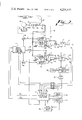
- FIG. 2 is a block diagram showing the functional relationships among the components of the machine of FIG. 1, and the control system configuration.
- FIG. 3 is a block diagram illustrating the control procedure carried out by the computer according to the disclosed embodiment.
- FIGS. 4a-4g illustrate the machine of FIG. 1 in use for various exercise motions and showing linkage positions, user positions, and paths of motion, (dotted lines), corresponding to several examples of different exercises among the infinite number of exercises possible with this machine.
- FIG. 5 is a representative plot of tangential velocity vs. tangential force for the Non-inertial, positive-negative, speed-limited (NPNS) exercise mode.
- FIG. 6 shows a side view of a preferred alternative embodiment of the invention.
- FIG. 7 is a front view of the embodiment shown in FIG. 6.
- FIG. 8 is an opposite side view of the embodiment as in FIG. 6.
- FIGS. 9a, b, c and d show some alternative embodiments of the present invention.
- the robotic exercise machine of the first disclosed embodiment has a first link 1 connected to a rigid frame 4 by a hinge joint 5, allowing this first link to rotate relative to the frame.
- a second link 2 is connected to the first link 1 by a hinge joint 6 allowing this second link to rotate relative to the first link.
- a yoke-bar 3 is shown mounted at the end of the second link 2 and has a pair of handles 32 which the user of the machine grips with his hands while exercising. This bar 3 is only one of many removable attachments which are available for use as user interaction means for this exercise machine.
- a few of these other removable attachments are: a pair of foot plates which receive forces exerted by the user's feet, a pair of padded surfaces for direct contact with the user's forearms, and a pair of padded surfaces for direct contact with the user's lower legs.
- a set of accessory furniture is also available for positioning or mounting on the platform 17, and includes benches, chairs, and various other supporting structures.
- This platform 17 is rigidly connected to the frame 4.
- the first link 1 is driven relative to the frame 4 by hydraulic cylinder 7.
- the second link 2 is driven relative to the first link by hydraulic cylinder 10.
- a hydraulic power supply 18 pumps fluid into the accumulator 19, which stores fluid under pressure.
- This accumulator 19 supplies fluid at high pressure to both cylinders 7 and 10.
- the flow rates of fluid into cylinder 7 and 10, and hence the speeds of the piston rods 35, are regulated by electro-hydraulic servo valves 13 and 14 respectively. Fluid enters these servo valves 13 and 14 through supply lines 33 and 34.
- Cylinder 7 is connected to platform 17 by a hinge joint 8, and to the hub 1a of link 1 by a hinge joint 9.
- Cylinder 10 is connected to the hub 1a of link 1 by a hinge joint 11 and to the hub 2a of link 2 by hinge joint 12.
- the geometry of the described linkage is such that the user interaction point 32, which is that point at which the body of the user makes contact with the yoke bar 3, can be made to move along any one of an infinite number of paths within a large planar region, at any desired velocity, by suitable control of the angular velocities of the two links 1 and 2. These angular velocities are produced by the motion of piston rods 35 relative to cylinders 7 and 10. Thus, the velocity of the user interaction point 32 is controlled by regulating the flow rates of fluid into cylinders 7 and 10 by means of servo valves 13 and 14.
- Suitable control of the velocity of user interaction point 32 makes possible the enforcement of any specified path of motion within a large planar region, and provides for any desired relationship between speed of movement along this path and the magnitudes of user-exerted forces.
- the primary element of the control system is a microcomputer 23.
- This microcomputer 23 supervises operation of the machine and computes velocity commands for the two links 1 and 2.
- the microcomputer 23 is also a part of the feedback loops which are responsible for carrying out these velocity commands.
- the following variables are sensed and fed into the microcomputer 23: the angular position of link 1 by transducer 21, the angular position of link 2 by transducer 20, and two perpendicular components of user-exerted force by transducer 22.
- An analog-to-digital converter 37 converts these analog electrical signals into digital signals for input into the microcomputer 23.
- the outputs of the microcomputer, the control signals for servo valves 13 and 14, are converted to analog electrical signals by digital-to-analog converters 38.
- the microcomputer 23 also serves as a communication link between the user and the machine.
- a user console 24 is interfaced with the microcomputer and allows the user to request various exercise modes and specify various parameters which define the form of an exercise to be done. The user enters this information at the keyboard 25.
- the display panel 26 displays characters entered by the user, for verification, and displays messages concerning his performance in a previous exercise session, messages which guide him through an exercise program, or messages concerning error conditions or machine malfunctions.
- the operator console 27 provides for more complicated interactions with the microcomputer, such as input and output of user performance data and the trajectory teaching and force-curve teaching operations described earlier.
- a magnetic tape unit 30 serves as a storage medium for performance data and exercise program data for a large number of users of the machine.
- the tape unit will store the data resulting from trajectory teaching and force-teaching sessions. Any of this data may be printed out for inspection by the printer 29. Data and commands are entered on keyboard 28.
- An optional disk storage unit 31 provides for storage of much larger quantities of data, and allows much faster access to the data.
- a digital display 41 is mounted near the end of the second link 2 by an adjustable bracket and serves to inform the user of the instantaneous level of force that he is exerting during exercise. This force indicated is normally the component of user-exerted force tangent to the specified trajectory. This force is computed by the microcomputer 23 and sent to the digital display 41 as a digital signal.
- the microcomputer 23 is shown as two distinct units, the supervisory computer 70 and the direct-digital-control computer 71. This is a functional distinction rather than a physical distinction. The same computer 23 performs both functions by sharing its time between them. It would be possible, however, to use separate computers or microprocessors for these two tasks.
- the supervisory task involves sampling at closely-spaced time intervals the measured values of link angular positions ⁇ 1 and ⁇ 2 and two components of the user exerted force F, F n , and F t where F n represents the component of user exerted force F normal to the desired path and F t represents the component of user exerted force F tangent to the desired path.
- F n represents the component of user exerted force F normal to the desired path
- F t represents the component of user exerted force F tangent to the desired path.
- These measured values along with programs and data defining the desired path which reside in computer memory, are used to compute commanded angular velocities ⁇ 1c and ⁇ 2c for the two links 1 and 2.
- These velocity commands are updated at closely-spaced time intervals in order to keep up with the changing state of the system.
- the computer makes use of recently sampled values of link angular positions ⁇ 1 and ⁇ 2 to approximate the present link angular velocities to a sufficient degree
- the direct-digital-control task involves receiving the velocity commands ⁇ 1c and ⁇ 2c and enforcing them.
- the present velocity errors are computed as the difference between actual link angular velocities and commanded link angular velocities ⁇ 1c and ⁇ 2c . These errors are then used by the computer to determine what corrections must be made to the electrical signals e 1 and e 2 in order to eliminate the errors between actual and commanded velocities.
- the signals e 1 and e 2 regulate the torque output of torque motors 72 and 73, which position servo valves 13 and 14 and thereby regulate the fluid flow rates into hydraulic cylinder 7 and 10. These servo valves are capable of regulating either flow or pressure to each end of the two cylinders 7 and 10 and thus serve to regulate either the velocities or the applied forces of the piston rods 35.
- FIG. 3 is a block diagram which illustrates the overall structure and function of the computer software. Each block represents an individual program or module and the lines show the primary inputs and outputs of each program.
- the sampling program 250 receives the present values of link positions and force transducer output from the computer's communication interface. These sampled values are then stored in computer memory locations where the values will be read by other programs. The values of link angular positon, ⁇ 1 and ⁇ 2 , are then used, along with previous values of position, to compute the angular velocities ⁇ 1 and ⁇ 2 , which are used by the servo-loop control programs.
- the two components of force transducer output, F 1 and F 2 are used in coordinate transformation equations to compute F t , the component of user-exerted force tangent to the specified trajectory.
- the sampled link angular positions ⁇ 1 and ⁇ 2 are transformed into components of linear position, C x and C y , in the horizontal and vertical directions. These coordinates give the location of the endpoint 32, (the point of interaction between the machine and the user). The position of the endpoint 32 relative to the specified trajectory is then determined. In order to correct for deviations of the endpoint from the specified trajectory, velocity components V ex and V ey are determined. These velocity components serve as an endpoint velocity command in the direction normal to the specified trajectory.
- the endpoint coordinates C x and C y are also used, along with data stored in memory, to determine a force parameter K.
- the sampled coordinates C x and C y are used to compute approximately the line integral of displacement along the trajectory.
- a table of data in computer memory contains values of K, as well as position coordinates of points on the specified trajectory, for a large number of evenly-spaced values of this line integral. K is found in this table according to the present value of the line integral.
- This parameter, K is responsible for the variation of resisting force with position along the specified trajectory.
- the K parameter is used along with F t to compute the commanded endpoint tangential velocity V ct , which serves to specify the machine behavior and thus the form of the exercise.
- V ct is then resolved into components in the horizontal and vertical directions, V ctx and V cty . These components are then added vectorially to Vex and Vey to form the resultant commanded endpoint velocity. This velocity is then converted into the equivalent link-angular-velocity commands, ⁇ 1c and ⁇ 2c .
- the equations used to compute link-angular-velocity are: ##EQU1## where
- C x is horizontal component of endpoint position
- C y is vertical component of endpoint position
- C y is vertical component of endpoint velocity
- L is length of each link 1 and 2 of the machine (both links are of the same length)
- ⁇ 1 is angular position of link 1, measured from the horizontal plane
- ⁇ 2 is the angle between the horizontal plane and the line segment extending from hinge joint 5 to the user interaction point and lying in the plane in which links 1 and 2 move.
- the differences between the commanded angular velocities and the actual angular velocities ⁇ 1 and ⁇ 2 are used by the two servo-loop control programs to compute M 1 and M 2 , the values of voltage to be supplied to the torque motors 72 and 73 of the electro-hydraulic servo-valves.
- M 1 and M 2 are computed from a proportional-integral derivative algorithm, which is well known to thosed skilled in the art of control system engineering.
- the computer 23 also serves to monitor the performance of the machine so that malfunctions may be detected. Monitoring is done indirectly by checking for excessively high errors in link angular velocities and for excessively high rates of increase in these errors. If malfunctions are detected the computer will send a digital signal to digital switch 74 causing this switch to open and break the circuit supplying electrical current to four safety-shut-off valves 15 and 16. These valves are normally closed, spring loaded, and solenoid operated, requiring continuous solenoid current to remain open. When closed, these valves block the flow of fluid into and out of the cylinders 7 and 10, locking the linkage in its present position and thereby preventing possible injury to the user.
- the primary elements of the hydraulic power supply 18 are also shown in FIG. 2. These are: a fixed delivery vane pump 75, a tank 76, a pilot-operated unloading valve 77, a check valve 79, two safety relief valves 78 and 80, and an accumulator 19.
- FIGS. 4a-4g are illustrations of the machine in use for various exercise motions.
- FIG. 4a shows the user 50 performing the familiar curl exercise, but the path of motion 51 may assume any shape or curvature desired.
- FIG. 4b shows an overhead press exercise with an individually tailored path of motion 52.
- FIG. 4c shows a bench press exercise.
- FIG. 4d shows an overhead pull exercise.
- FIG. 4e shows a high-intensity leg press exercise using foot plate attachment 56 and adjustable chair 55.
- FIG. 4f shows a leg-extension exercise using a padded attachment 58 which contacts the front of the user's lower leg and the upper surfaces of his feet.
- the path of motion 57 is circular with a radius and a center point exactly matched to the user's physical dimensions.
- FIG. 4g shows an exercise motion designed for involvement of both arms and legs over a long path of motion 59. These exercises shown are only a few of the infinite number of those possible with this robotic exercise machine.
- One such exercise mode is the non-inertial, positive-negative, speed limited exercise mode.
- the non-inertial positive-negative speed-limited exercise mode, (abbreviated NPNS) is expected to provide the most effective and widely used form of skeletal-muscle exercise. It is called “non-inertial” because, unlike exercise done with weights, the velocity of the bar, or other means of contact with the user, does not increase with time when the user exerts a constant force on the bar.
- the bar, or endpoint reacts according to the forces presently being applied, and its velocity is not affected by the time-history of user-exerted forces.
- NPNS exercise will be carried out in accordance with selected "force-curves" designed to vary the resisting force according to the strength potential of the user at any position along the path of motion.
- the speed at which the endpoint moves along a specified trajectory is proportional to the component of user-exerted force along this trajectory.
- An exception to this rule occurs when the force exceeds some limit or drops below some limit, in which case the speed will be held constant.
- the purpose of these speed restrictions is to insure that low-speed "isotonic" exercise is actually being done when a particular exercise program calls for this type of exercise.
- the NPNS exercise mode is extremely flexible. All parameters involved can be adjusted by the user at the operator's console 24. By adjusting certain force parameters, to be described next, the form of the exercise can range from the slowest isotonics to high-speed isokinetics, and from very heavy resistance to the lightest resistance.
- the tangential-velocity update program which is responsible for producing NPNS exercise will consist of the following procedures.
- the user has lost contact with the machine, either by intentionally releasing his grip or by losing his grip due to muscle exhaustion or accident.
- the force parameter K is the ratio of tangential user-exerted force F t to the average value of F t over a ST.
- the forces F t are those sampled during the previously described force teaching process.
- a table of values of K is formed during the force-teaching process described earlier. The correct value of K is obtained from this table according to the present value of the line integral of displacement along the trajectory, as was described earlier.
- a nominal force, F NOM is specified by the user at the user's console before an exercise set begins. The shifted forces are computed as follows:
- C 2 , C 3 , and C S are parameters which may either be specified by the user or assume standard values.
- the linkage must move into a specified starting position at or near the extreme end of the ST before an exercise set can begin. This will be accomplished by a subroutine designed specifically for this purpose.
- Non-inertial exercise (Velocity is not proportional to the time integral of applied force.)
- Positive-positive exercise Force exerted on the user by the machine is in the opposite direction during the reverse stroke from that during the forward stroke.
- the resisting force provided by the machine can be made to vary with position along a specified trajectory according to the user's strength-potential curve.
- FIGS. 6, 7 and 8 An alternative mechanical configuration of the robotic exercise machine is illustrated in FIGS. 6, 7 and 8.
- two links 201,202 move along straight-line paths to produce exercise motions similar to those of the configuration previously described.
- the user-interaction attachment 200 can move along any path within a large rectangular planar region.
- the first link 201 consists of a plate 203 and two sets of ball bushings, 204 and 205.
- Link 201 moves along a pair of vertical ways 206, which are rigidly connected to a pair of end plates 207. These end plates are rigidly connected to a supporting frame 208, to which a platform 209 is attached.
- the vertical ways 206 serve as a guideway along which the set of four ball bushings 204 move.
- a hydraulic motor 210 drives link 201 along the vertical ways 206.
- a drive sprocket 212 on the shaft of motor 210 drives a roller chain 211 in either of two directions. One end of the chain is connected to the bottom of plate 203. The chain extends downward, wraps around drive sprocket 212, then extends upward to the top of the frame 208, wraps around idler sprocket 213, and then extends downward to connect with the top of plate 203.
- a second link 202 is connected to the first link 201 by means of a set of four ball bushings 205. This arrangement allows link 202 to move along a straight path in the horizontal direction relative to link 201.
- This second link consists of a pair of horizontal ways 214 connected at each end by end plates 215 and 216.
- a second hydraulic motor 217 is mounted on plate 203 and drives link 202 in a straight-line motion relative to link 201.
- a roller chain 218 transmits power from motor 217 to link 202.
- a drive sprocket 219 is mounted on the shaft of motor 217.
- An idler sprocket 220 is mounted directly above the drive sprocket.
- the roller chain 218 is connected at one end to end plate 215 and extends horizontally to drive sprocket 219. It wraps around the drive sprocket and then around idler sprocket 220. From there it extends horizontally to connect with end plate 216.
- a two-component force transducer 221 is mounted on end plate 215.
- This transducer consists of two links 222 and 223, two rods 224 and 228, and two strain gauges 225.
- Link 222 is connected to end plate 215 by a hinge joint 226 and by rod 228.
- Link 223 is connected to link 222 by hinge joint 227 and by rod 224.
- Strain gauges 225 are mounted on rods 224 and 228.
- the user interaction attachment 200 is mounted on link 223 so that the point of application of user-exerted forces and the center of hinge joint 226 lie on a common line parallel to horizontal ways 214.
- FIGS. 9a-9c show still some more alternative mechanical configurations of the invention.
- FIG. 9a shows two additional links 80 and 81 which are attached to a guideway 84 by ball bushings or rollers so that they move in a straight line relative to link 2.
- the guideway 84 is rigidly attached to link 2.
- the links 80 and 81 are driven relative to the guideway 84 by hydraulic cylinders 85 and 86. Cylinder 85 is located below guideway 84, and cylinder 86 is located above the guideway.
- a pair of attachments 82 and 83 are located at the ends of links 80 and 81 for interaction with the user.
- This arrangement converts the apparatus shown in FIG. 1 into a machine capable of providing 3-dimensional exercise motions.
- the control system is expanded to control the velocities of links 80 and 81 as well as those of links 1 and 2.
- FIG. 9b The configuration of FIG. 9b is similar to the embodiment of FIG. 1 except that the second link takes the form of a link 87 which moves in a straight line relative to link 1, instead of a rotary motion.
- Link 87 is guided by a rod 88 which is attached to link 1 by means of ball bushing mounts 89.
- Link 87 is driven in a straight-line motion relative to link 1 by hydraulic cylinder 90, which is mounted rigidly to the side of link 1.
- a removable attachment 91 is mounted at the end of link 87, for interaction with the user. This machine is capable of motions similar to those of the preferred embodiment.
- FIG. 9c shows a machine, similar to that in FIG. 6, which makes use of two linear motions to achieve a range of movement comparable to that of the embodiment of FIG. 1.
- the first link 92 includes a double motor housing, which houses motors 93 and 94.
- the frame is comprised of a base 95, a group of two or more guide rods 96 and a screw shaft 97.
- Motor 93 rotates about screw shaft 97, turning a ball-screw about screw shaft 97, which causes first link 92 to be driven upward relative to the described frame.
- Motor 94 is offset from motor 93 to allow screw-shaft 97 and guide rods 96 to pass through first link 92.
- the second link 98 includes a screw-shaft 99, a group of two or more guide rods 100, two end plates 101, and a removable attachment 102 for interaction with the user.
- This second link is driven in a straight line relative to housing 92 by motor 94, which turns a ball-screw about screw-shaft 99.
- FIG. 9d shows a configuration capable of 3-dimensional motion and intended for use in pairs, one machine for a right body limb, a second machine for a left body limb.
- the third link 103 is identical to that of link 2 of the preferred embodiment and is driven in a rotary motion relative to link 105 by hydraulic cylinder 104.
- the second link 105 is driven in a rotary motion relative to the first link 107 by a hydraulic motor 106.
- the first link 107 is attached to frame 109 by a hinge joint allowing link 107 to rotate relative to frame 109 about an axis 110 perpendicular to the axis of rotation of link 105.
- Link 107 is driven by hydraulic motor 108.
Abstract
Description
F.sub.M1 =KF.sub.NOM F.sub.M2 =C.sub.2 F.sub.M1
F.sub.M3 =C.sub.3 F.sub.M1 F.sub.S =C.sub.S F.sub.M1
Claims (22)
Priority Applications (7)
| Application Number | Priority Date | Filing Date | Title |
|---|---|---|---|
| US05/921,568 US4235437A (en) | 1978-07-03 | 1978-07-03 | Robotic exercise machine and method |
| PCT/US1978/000228 WO1980000124A1 (en) | 1978-07-03 | 1978-12-12 | Feedback controlled exercise machine |
| DE7979900777T DE2862418D1 (en) | 1978-07-03 | 1978-12-15 | Programmable exercise machine |
| JP54501097A JPH0130502B2 (en) | 1978-07-03 | 1978-12-15 | |
| CA000318796A CA1118464A (en) | 1978-07-03 | 1978-12-21 | Robotic exercise machine |
| AU45225/79A AU520601B2 (en) | 1978-07-03 | 1979-03-19 | Robotic exercise machine |
| EP79900777A EP0016094B1 (en) | 1978-07-03 | 1980-02-12 | Programmable exercise machine |
Applications Claiming Priority (1)
| Application Number | Priority Date | Filing Date | Title |
|---|---|---|---|
| US05/921,568 US4235437A (en) | 1978-07-03 | 1978-07-03 | Robotic exercise machine and method |
Publications (1)
| Publication Number | Publication Date |
|---|---|
| US4235437A true US4235437A (en) | 1980-11-25 |
Family
ID=25445629
Family Applications (1)
| Application Number | Title | Priority Date | Filing Date |
|---|---|---|---|
| US05/921,568 Expired - Lifetime US4235437A (en) | 1978-07-03 | 1978-07-03 | Robotic exercise machine and method |
Country Status (7)
| Country | Link |
|---|---|
| US (1) | US4235437A (en) |
| EP (1) | EP0016094B1 (en) |
| JP (1) | JPH0130502B2 (en) |
| AU (1) | AU520601B2 (en) |
| CA (1) | CA1118464A (en) |
| DE (1) | DE2862418D1 (en) |
| WO (1) | WO1980000124A1 (en) |
Cited By (160)
| Publication number | Priority date | Publication date | Assignee | Title |
|---|---|---|---|---|
| WO1982002668A1 (en) * | 1981-01-30 | 1982-08-19 | Nautilus Sports Med Ind | Electronically monitored resistance exercising method and apparatus |
| US4354676A (en) * | 1978-10-13 | 1982-10-19 | Pepsico, Inc. | Exerciser |
| US4363481A (en) * | 1980-11-20 | 1982-12-14 | Erickson David T | Exercise device |
| US4444390A (en) * | 1980-11-20 | 1984-04-24 | Erickson David T | Hydraulic exercising device |
| US4478412A (en) * | 1982-05-26 | 1984-10-23 | Muir Arthur M | Exercise device and control valve therefor |
| US4479647A (en) * | 1981-12-30 | 1984-10-30 | Smith Robert S | Resistance exerciser |
| DE3318541A1 (en) * | 1983-05-20 | 1984-11-22 | Rudolf Hausherr & Söhne GmbH & Co KG, 4322 Sprockhövel | Training apparatus |
| WO1984004464A1 (en) * | 1983-05-18 | 1984-11-22 | Hydra Gym Athletics Inc | Computerized exercising device |
| US4499900A (en) * | 1982-11-26 | 1985-02-19 | Wright State University | System and method for treating paralyzed persons |
| US4509509A (en) * | 1983-07-11 | 1985-04-09 | Jean Bouvet | Apparatus for treating the joints of the human body |
| US4518163A (en) * | 1980-10-20 | 1985-05-21 | Arthur C. Bentley | Exerciser with electrically controlled resistance |
| US4529196A (en) * | 1983-02-25 | 1985-07-16 | Logan Robert C | Exercise device |
| US4563003A (en) * | 1983-04-15 | 1986-01-07 | Fernando Bugallo | Weight lifting apparatus having increased force on the return stroke |
| US4569518A (en) * | 1983-02-16 | 1986-02-11 | Fulks Kent B | Programmable exercise system |
| US4571682A (en) * | 1983-08-22 | 1986-02-18 | Computerized Sports Equipment, Inc. | System and method for skill enhancement and behavior modification |
| US4621620A (en) * | 1984-04-16 | 1986-11-11 | Gene Anderson | Human limb manipulation device |
| US4621623A (en) * | 1985-01-25 | 1986-11-11 | Leao Wang | Multi-function gymnastic device |
| US4629185A (en) * | 1985-07-11 | 1986-12-16 | Amann Michael J | Universal hydraulic exerciser |
| US4635933A (en) * | 1982-11-27 | 1987-01-13 | Josef Schnell | Training apparatus |
| US4642769A (en) * | 1983-06-10 | 1987-02-10 | Wright State University | Method and apparatus for providing stimulated exercise of paralyzed limbs |
| US4645205A (en) * | 1985-07-08 | 1987-02-24 | Wolff Leslie C | Athletic exerciser for paraplegics and quadriplegics |
| US4647041A (en) * | 1985-02-04 | 1987-03-03 | Whiteley Neville C | Exercise apparatus |
| US4647039A (en) * | 1984-11-08 | 1987-03-03 | Lee E. Keith | Impingement exerciser with force monitoring and feedback system |
| US4667955A (en) * | 1985-04-30 | 1987-05-26 | Giesch Nick J | Hydraulic universal gym |
| US4674741A (en) * | 1985-08-05 | 1987-06-23 | Bally Manufacturing Corporation | Rowing machine with video display |
| US4691694A (en) * | 1984-11-29 | 1987-09-08 | Biodex Corporation | Muscle exercise and rehabilitation apparatus |
| US4705271A (en) * | 1984-12-21 | 1987-11-10 | Applied Power Inc. | Exercise apparatus |
| US4727860A (en) * | 1986-06-06 | 1988-03-01 | Isotechnologies, Inc. | Exercise apparatus for the knee |
| US4765613A (en) * | 1987-01-22 | 1988-08-23 | Paramount Fitness Equipment Corporation | Progressive resistance exercise device |
| US4779865A (en) * | 1987-06-11 | 1988-10-25 | Lieberman David E | Exercise/therapy support system |
| WO1989002295A1 (en) * | 1987-09-16 | 1989-03-23 | Joseph Patrick Mcgillis | Multidirectional exerciser |
| US4817940A (en) * | 1986-04-04 | 1989-04-04 | Fike Corporation | Computerized exercise monitoring system and method for comparing present and past exercise activities |
| US4828257A (en) * | 1986-05-20 | 1989-05-09 | Powercise International Corporation | Electronically controlled exercise system |
| US4846458A (en) * | 1987-08-06 | 1989-07-11 | Tri-Tech, Inc. | Upper body exercise apparatus |
| US4846466A (en) * | 1987-11-20 | 1989-07-11 | Stima Iii Michael W | Microprocessor controlled electro-hydraulic exercise system |
| WO1989007471A1 (en) * | 1988-02-16 | 1989-08-24 | Rio-Flex Corporation | Abdominal musculature development method and device |
| US4863161A (en) * | 1985-04-22 | 1989-09-05 | Telle Jerome R | Exercise isokinetic apparatus |
| US4869498A (en) * | 1987-02-17 | 1989-09-26 | Kst-Motorenversuch Gmbh & Co. Kg | Isokinetic ergometer |
| US4884445A (en) * | 1988-11-28 | 1989-12-05 | Armin M. Sadoff | Grip strength analyzer apparatus and method of using same |
| US4885939A (en) * | 1988-01-21 | 1989-12-12 | Lumex, Inc. | Dynamometer for testing eccentric contractions and concentric contractions with free-limb acceleration |
| US4893808A (en) * | 1988-01-26 | 1990-01-16 | Mcintyre Donald R | Exercise apparatus for the neck |
| US4907795A (en) * | 1986-04-04 | 1990-03-13 | Fike Corporation | Computerized exercise monitoring system and method for monitoring a user's exercise performance |
| US4934695A (en) * | 1988-04-16 | 1990-06-19 | Friedrich Wolff | Exercising apparatus |
| US4969643A (en) * | 1989-06-07 | 1990-11-13 | Helmut Kroeker | Exercise apparatus |
| US4979735A (en) * | 1988-08-01 | 1990-12-25 | Stewart John V | Hydraulic exercise device with work measurement |
| US4986261A (en) * | 1987-01-30 | 1991-01-22 | Superspine, Inc. | Apparatus for performing coordinated walking motions with the spine in an unloaded state |
| US5011142A (en) * | 1989-11-20 | 1991-04-30 | Christopher Eckler | Exercise control system |
| WO1991007213A1 (en) * | 1989-11-13 | 1991-05-30 | Walker Fitness Systems, Inc. | Automatic force generating and control system |
| US5020795A (en) * | 1989-06-07 | 1991-06-04 | Soma Dynamics Corporation | Physical therapy and exercise apparatus for body limbs |
| US5026046A (en) * | 1990-01-10 | 1991-06-25 | Decloux Richard J | Adjustable auxiliary hydraulic fluid accumulator control for hydraulically-phased stair climbing exercise apparatus |
| US5052379A (en) * | 1989-04-27 | 1991-10-01 | Soma Dynamics Corporation | Combination brace and wearable exercise apparatus for body joints |
| US5054774A (en) * | 1990-06-12 | 1991-10-08 | Chattecx | Computer-controlled muscle exercising machine having simplified data access |
| US5078152A (en) * | 1985-06-23 | 1992-01-07 | Loredan Biomedical, Inc. | Method for diagnosis and/or training of proprioceptor feedback capabilities in a muscle and joint system of a human patient |
| US5085429A (en) * | 1988-02-16 | 1992-02-04 | Hoeven Martin A V D | Musculature exercising method |
| US5098088A (en) * | 1990-10-09 | 1992-03-24 | Alan Cohen | Exercise machine for handicapped or disabled persons |
| USRE34212E (en) * | 1987-08-06 | 1993-04-06 | Tri-Tech, Inc. | Upper body exercise apparatus |
| US5209715A (en) * | 1989-11-13 | 1993-05-11 | Walker Fitness Systems, Inc. | Automatic force generating and control system |
| US5209714A (en) * | 1989-11-13 | 1993-05-11 | Walker Fitness Systems, Inc. | Automatic force generating and control system |
| US5211161A (en) * | 1991-01-22 | 1993-05-18 | Compagnie Generale De Materiel Orthopedique | Three axis passive motion exerciser |
| US5228429A (en) * | 1991-01-14 | 1993-07-20 | Tadashi Hatano | Position measuring device for endoscope |
| US5230672A (en) * | 1991-03-13 | 1993-07-27 | Motivator, Inc. | Computerized exercise, physical therapy, or rehabilitating apparatus with improved features |
| US5256117A (en) * | 1990-10-10 | 1993-10-26 | Stairmaster Sports Medical Products, Inc. | Stairclimbing and upper body, exercise apparatus |
| US5275045A (en) * | 1991-03-07 | 1994-01-04 | Isotechnologies, Inc. | Apparatus and method for use in assessing the lifting capability of a human subject |
| US5282835A (en) * | 1992-03-04 | 1994-02-01 | Wright Howard S | Exercising table for applying cyclic movement with adjustable support members |
| US5299998A (en) * | 1990-10-16 | 1994-04-05 | Hutchins Kenneth M | Linear movement, trunk muscle exercise machine |
| US5344374A (en) * | 1992-06-02 | 1994-09-06 | Telle Jerome R | Variable resistance exercising apparatus |
| US5348519A (en) * | 1988-02-04 | 1994-09-20 | Loredan Biomedical, Inc. | Exercise and diagnostic apparatus and method |
| US5356353A (en) * | 1991-05-22 | 1994-10-18 | Hideo Takaoka | Exercised device having an apparatus for monitoring and controlling the range of motion of the exercise device |
| US5362297A (en) * | 1993-04-14 | 1994-11-08 | Muir Arthur M | Exercise machine |
| US5391128A (en) * | 1991-06-06 | 1995-02-21 | Rahabilitation Institute Of Michigan | Object delivery exercise system and method |
| US5413546A (en) * | 1990-11-13 | 1995-05-09 | Basile; Vincent F. | Bicep exercise device |
| USRE34959E (en) * | 1986-08-04 | 1995-05-30 | Stairmaster Sports/Medical Products, Inc. | Stair-climbing exercise apparatus |
| US5466213A (en) * | 1993-07-06 | 1995-11-14 | Massachusetts Institute Of Technology | Interactive robotic therapist |
| US5480367A (en) * | 1987-10-26 | 1996-01-02 | Sportsquip Limited | Adductor/abductor exercise device |
| US5486150A (en) * | 1993-04-30 | 1996-01-23 | Randolph; Lucian | Exercise system, apparatus and method |
| US5499959A (en) * | 1991-04-15 | 1996-03-19 | Stairmaster Sports/Medical Products, Inc. | Upper body exercise apparatus |
| US5580341A (en) * | 1995-03-01 | 1996-12-03 | Lumex, Inc. | Shoulder press exercise machine and method of exercising |
| US5597373A (en) * | 1991-11-08 | 1997-01-28 | Cedaron Medical, Inc. | Physiological evaluation and exercise system |
| US5616111A (en) * | 1993-04-30 | 1997-04-01 | Randolph; Lucian | Exoskeletal exercise system |
| US5628715A (en) * | 1995-02-14 | 1997-05-13 | Cybex International, Inc. | Squat press exercise machine |
| USRE35598E (en) * | 1988-11-28 | 1997-09-02 | Sadoff; Armin M. | Strength analyzer and method of using same |
| US5704253A (en) * | 1995-03-09 | 1998-01-06 | Georgia Tech Research Corporation | Trajectory guidance apparatus and method |
| US5755645A (en) * | 1997-01-09 | 1998-05-26 | Boston Biomotion, Inc. | Exercise apparatus |
| US5769757A (en) * | 1996-06-21 | 1998-06-23 | Fulks; Kent | Method and apparatus for exercise with forced pronation or supination |
| US5794621A (en) * | 1995-11-03 | 1998-08-18 | Massachusetts Institute Of Technology | System and method for medical imaging utilizing a robotic device, and robotic device for use in medical imaging |
| US5814038A (en) * | 1995-06-07 | 1998-09-29 | Sri International | Surgical manipulator for a telerobotic system |
| US5830160A (en) * | 1997-04-18 | 1998-11-03 | Reinkensmeyer; David J. | Movement guiding system for quantifying diagnosing and treating impaired movement performance |
| US5890996A (en) * | 1996-05-30 | 1999-04-06 | Interactive Performance Monitoring, Inc. | Exerciser and physical performance monitoring system |
| US6387065B1 (en) * | 1996-09-30 | 2002-05-14 | Kinetic Concepts, Inc. | Remote controllable medical pumping apparatus |
| EP1334750A1 (en) * | 2002-02-08 | 2003-08-13 | Simon Alan Hogg | Exercise apparatus |
| US20030220175A1 (en) * | 2002-05-21 | 2003-11-27 | Durfee David L. | Abdominal exercise machine |
| US6672157B2 (en) | 2001-04-02 | 2004-01-06 | Northern Illinois University | Power tester |
| US6773376B2 (en) | 2002-10-23 | 2004-08-10 | Ramot At Tel Aviv University Ltd. | System and method for deriving angular isokinetic measurements using a linear dynamometer |
| FR2875140A1 (en) * | 2004-07-02 | 2006-03-17 | Univ Reims Champagne Ardenne | Training and rehabilitation method for improving sports gesture of athlete, involves loading personalized knee kinematics model and parameters relative to type of physical exercise in order to force knee to follow preset movement |
| US7070545B2 (en) | 2002-07-01 | 2006-07-04 | Nautilus, Inc. | Leg press and abdominal crunch exercise machine |
| US7083554B1 (en) | 1997-02-27 | 2006-08-01 | Nautilus, Inc. | Exercise machine with infinite position range limiter and automatic belt tensioning system |
| US7108641B2 (en) | 2000-05-03 | 2006-09-19 | Nautilus, Inc. | Exercise equipment with multi-positioning handles |
| US20060281606A1 (en) * | 1998-06-09 | 2006-12-14 | Radow Scott B | Exercise device and method for simulating physical activity |
| US20070042877A1 (en) * | 2003-05-15 | 2007-02-22 | Choi Yun-Seok | Apparatus for three-dimensional anaerobic exercise |
| US7220221B2 (en) | 2000-05-03 | 2007-05-22 | Nautilus, Inc. | Exercise device with body extension mechanism |
| US20070219072A1 (en) * | 2005-05-10 | 2007-09-20 | Kessler David K | Universal exercise apparatus |
| US20070265146A1 (en) * | 2006-05-11 | 2007-11-15 | Jan Kowalczewski | Method and apparatus for automated delivery of therapeutic exercises of the upper extremity |
| US20090075793A1 (en) * | 2003-11-13 | 2009-03-19 | Patrick John Trainor | Exercise devices |
| US20100023163A1 (en) * | 2008-06-27 | 2010-01-28 | Kidd Cory D | Apparatus and Method for Assisting in Achieving Desired Behavior Patterns |
| WO2010054447A2 (en) * | 2008-11-14 | 2010-05-20 | Bruno Lequeux | Rehabilitation device |
| US20100125026A1 (en) * | 2008-11-16 | 2010-05-20 | Vyacheslav Zavadsky | Wireless game controller for strength training and physiotherapy |
| US7833135B2 (en) | 2007-06-27 | 2010-11-16 | Scott B. Radow | Stationary exercise equipment |
| US7841970B2 (en) | 2006-07-28 | 2010-11-30 | Michael Striar | Variable weight device |
| US7862476B2 (en) | 2005-12-22 | 2011-01-04 | Scott B. Radow | Exercise device |
| US7922635B2 (en) | 2000-03-10 | 2011-04-12 | Nautilus, Inc. | Adjustable-load unitary multi-position bench exercise unit |
| EP2316543A1 (en) * | 2009-10-27 | 2011-05-04 | Michael Barth | Device for training the musculature of a person |
| EP2316539A1 (en) * | 2009-10-27 | 2011-05-04 | Michael Barth | Device for training the musculature of a person |
| US8012073B2 (en) | 2009-12-22 | 2011-09-06 | Michael Charles Barnett | Fitness machine with automated variable resistance |
| US20110224583A1 (en) * | 2008-11-14 | 2011-09-15 | Bruno Lequeux | Rehabilitation Device |
| US20130065730A1 (en) * | 2010-01-07 | 2013-03-14 | Antonio Camerota | Machine for the power exercise of a user |
| US8491572B2 (en) | 2004-11-15 | 2013-07-23 | Izex Technologies, Inc. | Instrumented orthopedic and other medical implants |
| US20140077494A1 (en) * | 2012-09-14 | 2014-03-20 | Robert Sutkowski | Methods and apparatus to power an exercise machine |
| US8678979B2 (en) | 1998-09-01 | 2014-03-25 | Izex Technologies, Inc. | Remote monitoring of a patient |
| US8784475B2 (en) | 2004-11-15 | 2014-07-22 | Izex Technologies, Inc. | Instrumented implantable stents, vascular grafts and other medical devices |
| US8790258B2 (en) | 1999-06-23 | 2014-07-29 | Izex Technologies, Inc. | Remote psychological evaluation |
| US9050498B2 (en) | 2013-03-04 | 2015-06-09 | Brunswick Corporation | Exercise assemblies having foot pedal members that are movable along user defined paths |
| US20150224365A1 (en) * | 2006-12-28 | 2015-08-13 | Precor Incorporated | Exercise device path traces |
| US9114275B2 (en) | 2013-03-04 | 2015-08-25 | Brunswick Corporation | Exercise assemblies having crank members with limited rotation |
| US9138614B2 (en) | 2013-03-04 | 2015-09-22 | Brunswick Corporation | Exercise assemblies having linear motion synchronizing mechanism |
| US20160158601A1 (en) * | 2014-12-04 | 2016-06-09 | Korea Polytechnic University Industry Academic Cooperation Foundation | Human muscular strength amplification robot driven by intention of user and driving method thereof |
| US9610475B1 (en) | 2014-11-11 | 2017-04-04 | Brunswick Corporation | Linear motion synchronizing mechanism and exercise assemblies having linear motion synchronizing mechanism |
| US9772240B2 (en) | 2014-10-09 | 2017-09-26 | Rethink Motion, Inc. | Elastic torque sensor for planar torsion spring |
| US9833662B2 (en) | 2014-10-09 | 2017-12-05 | Rethink Motion, Inc. | Series elastic motorized exercise machine |
| US10094055B2 (en) | 2016-03-14 | 2018-10-09 | Abm International, Inc. | Method, apparatus and computer-readable medium for moving |
| US10118073B2 (en) | 2016-04-04 | 2018-11-06 | Worldpro Group, LLC | Interactive apparatus and methods for muscle strengthening |
| US10188890B2 (en) | 2013-12-26 | 2019-01-29 | Icon Health & Fitness, Inc. | Magnetic resistance mechanism in a cable machine |
| US10252109B2 (en) | 2016-05-13 | 2019-04-09 | Icon Health & Fitness, Inc. | Weight platform treadmill |
| US10258828B2 (en) | 2015-01-16 | 2019-04-16 | Icon Health & Fitness, Inc. | Controls for an exercise device |
| US10272317B2 (en) | 2016-03-18 | 2019-04-30 | Icon Health & Fitness, Inc. | Lighted pace feature in a treadmill |
| US10279212B2 (en) | 2013-03-14 | 2019-05-07 | Icon Health & Fitness, Inc. | Strength training apparatus with flywheel and related methods |
| US10293211B2 (en) | 2016-03-18 | 2019-05-21 | Icon Health & Fitness, Inc. | Coordinated weight selection |
| CN109939415A (en) * | 2019-04-17 | 2019-06-28 | 福州大学 | A kind of active rehabilitation machines in parallel and its assembly method with high movement angle |
| US10343017B2 (en) | 2016-11-01 | 2019-07-09 | Icon Health & Fitness, Inc. | Distance sensor for console positioning |
| US10376736B2 (en) | 2016-10-12 | 2019-08-13 | Icon Health & Fitness, Inc. | Cooling an exercise device during a dive motor runway condition |
| US10426989B2 (en) | 2014-06-09 | 2019-10-01 | Icon Health & Fitness, Inc. | Cable system incorporated into a treadmill |
| US10433612B2 (en) | 2014-03-10 | 2019-10-08 | Icon Health & Fitness, Inc. | Pressure sensor to quantify work |
| US10441844B2 (en) | 2016-07-01 | 2019-10-15 | Icon Health & Fitness, Inc. | Cooling systems and methods for exercise equipment |
| US10449416B2 (en) | 2015-08-26 | 2019-10-22 | Icon Health & Fitness, Inc. | Strength exercise mechanisms |
| US10471299B2 (en) | 2016-07-01 | 2019-11-12 | Icon Health & Fitness, Inc. | Systems and methods for cooling internal exercise equipment components |
| US10493349B2 (en) | 2016-03-18 | 2019-12-03 | Icon Health & Fitness, Inc. | Display on exercise device |
| US10500473B2 (en) | 2016-10-10 | 2019-12-10 | Icon Health & Fitness, Inc. | Console positioning |
| US10543395B2 (en) | 2016-12-05 | 2020-01-28 | Icon Health & Fitness, Inc. | Offsetting treadmill deck weight during operation |
| US10561894B2 (en) | 2016-03-18 | 2020-02-18 | Icon Health & Fitness, Inc. | Treadmill with removable supports |
| US10610725B2 (en) | 2015-04-20 | 2020-04-07 | Crew Innovations, Llc | Apparatus and method for increased realism of training on exercise machines |
| US10625114B2 (en) | 2016-11-01 | 2020-04-21 | Icon Health & Fitness, Inc. | Elliptical and stationary bicycle apparatus including row functionality |
| US10625137B2 (en) | 2016-03-18 | 2020-04-21 | Icon Health & Fitness, Inc. | Coordinated displays in an exercise device |
| US10661114B2 (en) | 2016-11-01 | 2020-05-26 | Icon Health & Fitness, Inc. | Body weight lift mechanism on treadmill |
| US10729965B2 (en) | 2017-12-22 | 2020-08-04 | Icon Health & Fitness, Inc. | Audible belt guide in a treadmill |
| US10940360B2 (en) | 2015-08-26 | 2021-03-09 | Icon Health & Fitness, Inc. | Strength exercise mechanisms |
| US10953305B2 (en) | 2015-08-26 | 2021-03-23 | Icon Health & Fitness, Inc. | Strength exercise mechanisms |
| US11040231B2 (en) | 2017-01-30 | 2021-06-22 | Arena Innovation Corp. | Systems for dynamic resistance training |
| US11123609B2 (en) | 2018-05-14 | 2021-09-21 | Arena Innovation Corp. | Strength training and exercise platform |
| US11364419B2 (en) | 2019-02-21 | 2022-06-21 | Scott B. Radow | Exercise equipment with music synchronization |
| US11451108B2 (en) | 2017-08-16 | 2022-09-20 | Ifit Inc. | Systems and methods for axial impact resistance in electric motors |
| US11628117B2 (en) | 2014-09-01 | 2023-04-18 | Samsung Electronics Co., Ltd. | Torque pattern adjustment apparatus and method for adjusting torque pattern using the same |
Families Citing this family (29)
| Publication number | Priority date | Publication date | Assignee | Title |
|---|---|---|---|---|
| SE429926B (en) * | 1979-10-24 | 1983-10-10 | Emil Franken Smidak | MOTION PROMOTION DEVICE |
| EP0041509A1 (en) * | 1979-12-14 | 1981-12-16 | LEWIS, Robert Harrison | Exercising device |
| FR2501050A2 (en) * | 1981-01-12 | 1982-09-10 | Rosenblatt Paul | Exercise frame for developing muscle groups - has seat and pivoting handle joined to adjustable piston and cylinder |
| GB2124916A (en) * | 1982-08-11 | 1984-02-29 | Charles David Sinclair Gaskill | Exercise apparatus |
| SE454405B (en) * | 1983-01-11 | 1988-05-02 | Ingvar Lantz | MUSCLE BUILDER |
| EP0318126A1 (en) * | 1983-05-18 | 1989-05-31 | Hydra-Gym Athletics, Inc. | Computerized exercising device |
| GB2157578A (en) * | 1984-04-24 | 1985-10-30 | Paul Andrew Weston | Electrically controlled exercise apparatus |
| US4628910A (en) * | 1984-11-29 | 1986-12-16 | Biodex Corporation | Muscle exercise and rehabilitation apparatus |
| WO1986005699A1 (en) * | 1985-04-03 | 1986-10-09 | David John Piper | Exercise machine |
| GB8509968D0 (en) * | 1985-04-18 | 1985-05-30 | Rawcliffe J | Physiotherapy apparatus |
| AT397033B (en) * | 1985-05-24 | 1994-01-25 | Wintersteiger Gmbh & Co | DEVICE FOR DETECTING THE MUSCLE FORCE |
| WO1987001601A1 (en) * | 1985-09-20 | 1987-03-26 | Wintersteiger Gesellschaft M.B.H. & Co. | Training or ergometer device |
| GB2184361B (en) * | 1985-12-20 | 1989-10-11 | Ind Tech Res Inst | Automatic treadmill |
| EP0235312A3 (en) * | 1986-02-14 | 1987-12-09 | Computerized Sports Equipment, Inc. | System and method for skill enhancement and behavior modification |
| EP0246771A3 (en) * | 1986-05-20 | 1989-11-23 | Powercise International Corporation | Electronically controlled exercise system |
| JPS6373978A (en) * | 1986-06-23 | 1988-04-04 | ロ−アダン バイオメデイカル インコ−ポレ−テツド | Method for diagnosing and/or training feedback capacity of sensory terminal organ in muscle and joint system |
| FR2602083B1 (en) * | 1986-07-25 | 1989-03-24 | Sodilors Sa | BEACON OR SIGNALING DEVICE |
| CH669725A5 (en) * | 1986-08-01 | 1989-04-14 | Carlo Petralli | |
| US4869497A (en) * | 1987-01-20 | 1989-09-26 | Universal Gym Equipment, Inc. | Computer controlled exercise machine |
| US4746113A (en) * | 1987-02-24 | 1988-05-24 | Kissel Robert M | Automatically adjustable exercise equipment, and control system and method therefor |
| WO1988007879A1 (en) * | 1987-04-13 | 1988-10-20 | Fi. Ma Srl | Electronic device to employ in machines for physical exercises to carry out resistance values with variable intensity |
| FR2619723B1 (en) * | 1987-08-31 | 1990-01-19 | Angelloz Louis | MULTIPLE MODEL PHYSICAL EXERCISE APPARATUS AND METHOD FOR CONTROLLING SUCH APPARATUS |
| EP0327094A1 (en) * | 1988-02-02 | 1989-08-09 | Nokia Mechatronics Gmbh | Industrial robot |
| WO1991012854A1 (en) * | 1990-02-22 | 1991-09-05 | Tamalla Pty Ltd | Exercise apparatus |
| CN105832491B (en) * | 2015-01-12 | 2018-03-27 | 上银科技股份有限公司 | Upper limbs rehabilitation equipment |
| US9375598B1 (en) * | 2015-02-09 | 2016-06-28 | Hiwin Technologies Corp. | Upper extremity rehabilitation device |
| DE102019205676A1 (en) | 2019-04-18 | 2020-10-22 | Robert Bosch Gmbh | Strength training device |
| CN113521655B (en) * | 2021-07-12 | 2022-07-01 | 南阳市第二人民医院 | Cardiovascular disease rehabilitation device |
| CN113397919B (en) * | 2021-07-21 | 2022-04-01 | 深圳市大寰机器人科技有限公司 | Exoskeleton robot for ankle rehabilitation |
Citations (11)
| Publication number | Priority date | Publication date | Assignee | Title |
|---|---|---|---|---|
| US3395698A (en) * | 1965-10-01 | 1968-08-06 | Mc Donnell Douglas Corp | Physiologically paced ergomeric system |
| US3572700A (en) * | 1968-07-08 | 1971-03-30 | Joseph A Mastropaolo | Frictonal type exercising device |
| US3750479A (en) * | 1972-05-08 | 1973-08-07 | Nasa | Tilting table for ergometer and for other biomedical devices |
| US3770267A (en) * | 1972-03-08 | 1973-11-06 | Carthy M Mc | Exercising machine having plural exercising implements thereon |
| US3848467A (en) * | 1972-07-10 | 1974-11-19 | E Flavell | Proportioned resistance exercise servo system |
| US3858873A (en) * | 1971-08-17 | 1975-01-07 | Arthur A Jones | Weight lifting exercising devices |
| US3869121A (en) * | 1972-07-10 | 1975-03-04 | Evan R Flavell | Proportioned resistance exercise servo system |
| US3912265A (en) * | 1974-09-19 | 1975-10-14 | Arthur M Muir | Fluid flow resistance exerciser having selectively reversible fluid flow control means |
| US3989240A (en) * | 1975-05-06 | 1976-11-02 | Victor Bernard J | Electrically timed exercising device |
| US4050310A (en) * | 1976-03-17 | 1977-09-27 | Keiser Dennis L | Exercising apparatus |
| US4063726A (en) * | 1976-04-26 | 1977-12-20 | Wilson Robert J | Electronically controlled hydraulic exercising system |
Family Cites Families (3)
| Publication number | Priority date | Publication date | Assignee | Title |
|---|---|---|---|---|
| GB1051818A (en) * | 1965-09-14 | 1900-01-01 | ||
| GB1350068A (en) * | 1970-06-23 | 1974-04-18 | Stewart J S S | Physiotherapy control device |
| DE2706408A1 (en) * | 1977-02-15 | 1978-08-17 | Mathias Oechsler | Leg exercise hardness suspended from sensing frame - measures and increases movement produced by own effort of patient |
-
1978
- 1978-07-03 US US05/921,568 patent/US4235437A/en not_active Expired - Lifetime
- 1978-12-12 WO PCT/US1978/000228 patent/WO1980000124A1/en unknown
- 1978-12-15 JP JP54501097A patent/JPH0130502B2/ja not_active Expired
- 1978-12-15 DE DE7979900777T patent/DE2862418D1/en not_active Expired
- 1978-12-21 CA CA000318796A patent/CA1118464A/en not_active Expired
-
1979
- 1979-03-19 AU AU45225/79A patent/AU520601B2/en not_active Ceased
-
1980
- 1980-02-12 EP EP79900777A patent/EP0016094B1/en not_active Expired
Patent Citations (11)
| Publication number | Priority date | Publication date | Assignee | Title |
|---|---|---|---|---|
| US3395698A (en) * | 1965-10-01 | 1968-08-06 | Mc Donnell Douglas Corp | Physiologically paced ergomeric system |
| US3572700A (en) * | 1968-07-08 | 1971-03-30 | Joseph A Mastropaolo | Frictonal type exercising device |
| US3858873A (en) * | 1971-08-17 | 1975-01-07 | Arthur A Jones | Weight lifting exercising devices |
| US3770267A (en) * | 1972-03-08 | 1973-11-06 | Carthy M Mc | Exercising machine having plural exercising implements thereon |
| US3750479A (en) * | 1972-05-08 | 1973-08-07 | Nasa | Tilting table for ergometer and for other biomedical devices |
| US3848467A (en) * | 1972-07-10 | 1974-11-19 | E Flavell | Proportioned resistance exercise servo system |
| US3869121A (en) * | 1972-07-10 | 1975-03-04 | Evan R Flavell | Proportioned resistance exercise servo system |
| US3912265A (en) * | 1974-09-19 | 1975-10-14 | Arthur M Muir | Fluid flow resistance exerciser having selectively reversible fluid flow control means |
| US3989240A (en) * | 1975-05-06 | 1976-11-02 | Victor Bernard J | Electrically timed exercising device |
| US4050310A (en) * | 1976-03-17 | 1977-09-27 | Keiser Dennis L | Exercising apparatus |
| US4063726A (en) * | 1976-04-26 | 1977-12-20 | Wilson Robert J | Electronically controlled hydraulic exercising system |
Non-Patent Citations (1)
| Title |
|---|
| Iron Man; "`Time Machines` by Nautilus," Jul. 1973; pp. 42, 48-50. * |
Cited By (207)
| Publication number | Priority date | Publication date | Assignee | Title |
|---|---|---|---|---|
| US4354676A (en) * | 1978-10-13 | 1982-10-19 | Pepsico, Inc. | Exerciser |
| US4518163A (en) * | 1980-10-20 | 1985-05-21 | Arthur C. Bentley | Exerciser with electrically controlled resistance |
| US4363481A (en) * | 1980-11-20 | 1982-12-14 | Erickson David T | Exercise device |
| US4444390A (en) * | 1980-11-20 | 1984-04-24 | Erickson David T | Hydraulic exercising device |
| WO1982002668A1 (en) * | 1981-01-30 | 1982-08-19 | Nautilus Sports Med Ind | Electronically monitored resistance exercising method and apparatus |
| US4479647A (en) * | 1981-12-30 | 1984-10-30 | Smith Robert S | Resistance exerciser |
| US4478412A (en) * | 1982-05-26 | 1984-10-23 | Muir Arthur M | Exercise device and control valve therefor |
| US4499900A (en) * | 1982-11-26 | 1985-02-19 | Wright State University | System and method for treating paralyzed persons |
| US4635933A (en) * | 1982-11-27 | 1987-01-13 | Josef Schnell | Training apparatus |
| US4726582A (en) * | 1983-02-16 | 1988-02-23 | Fulks Kent B | Programmable exercise system |
| US4569518A (en) * | 1983-02-16 | 1986-02-11 | Fulks Kent B | Programmable exercise system |
| US4529196A (en) * | 1983-02-25 | 1985-07-16 | Logan Robert C | Exercise device |
| US4563003A (en) * | 1983-04-15 | 1986-01-07 | Fernando Bugallo | Weight lifting apparatus having increased force on the return stroke |
| US4566692A (en) * | 1983-05-18 | 1986-01-28 | Brentham Jerry D | Computerized exercising device |
| WO1984004464A1 (en) * | 1983-05-18 | 1984-11-22 | Hydra Gym Athletics Inc | Computerized exercising device |
| DE3318541A1 (en) * | 1983-05-20 | 1984-11-22 | Rudolf Hausherr & Söhne GmbH & Co KG, 4322 Sprockhövel | Training apparatus |
| US4642769A (en) * | 1983-06-10 | 1987-02-10 | Wright State University | Method and apparatus for providing stimulated exercise of paralyzed limbs |
| US4509509A (en) * | 1983-07-11 | 1985-04-09 | Jean Bouvet | Apparatus for treating the joints of the human body |
| US4571682A (en) * | 1983-08-22 | 1986-02-18 | Computerized Sports Equipment, Inc. | System and method for skill enhancement and behavior modification |
| US4621620A (en) * | 1984-04-16 | 1986-11-11 | Gene Anderson | Human limb manipulation device |
| US4647039A (en) * | 1984-11-08 | 1987-03-03 | Lee E. Keith | Impingement exerciser with force monitoring and feedback system |
| US4691694A (en) * | 1984-11-29 | 1987-09-08 | Biodex Corporation | Muscle exercise and rehabilitation apparatus |
| US4705271A (en) * | 1984-12-21 | 1987-11-10 | Applied Power Inc. | Exercise apparatus |
| US4621623A (en) * | 1985-01-25 | 1986-11-11 | Leao Wang | Multi-function gymnastic device |
| US4647041A (en) * | 1985-02-04 | 1987-03-03 | Whiteley Neville C | Exercise apparatus |
| US4863161A (en) * | 1985-04-22 | 1989-09-05 | Telle Jerome R | Exercise isokinetic apparatus |
| US4667955A (en) * | 1985-04-30 | 1987-05-26 | Giesch Nick J | Hydraulic universal gym |
| US5078152A (en) * | 1985-06-23 | 1992-01-07 | Loredan Biomedical, Inc. | Method for diagnosis and/or training of proprioceptor feedback capabilities in a muscle and joint system of a human patient |
| US4645205A (en) * | 1985-07-08 | 1987-02-24 | Wolff Leslie C | Athletic exerciser for paraplegics and quadriplegics |
| US4629185A (en) * | 1985-07-11 | 1986-12-16 | Amann Michael J | Universal hydraulic exerciser |
| US4674741A (en) * | 1985-08-05 | 1987-06-23 | Bally Manufacturing Corporation | Rowing machine with video display |
| US4817940A (en) * | 1986-04-04 | 1989-04-04 | Fike Corporation | Computerized exercise monitoring system and method for comparing present and past exercise activities |
| US4907795A (en) * | 1986-04-04 | 1990-03-13 | Fike Corporation | Computerized exercise monitoring system and method for monitoring a user's exercise performance |
| US4828257A (en) * | 1986-05-20 | 1989-05-09 | Powercise International Corporation | Electronically controlled exercise system |
| US4727860A (en) * | 1986-06-06 | 1988-03-01 | Isotechnologies, Inc. | Exercise apparatus for the knee |
| USRE34959E (en) * | 1986-08-04 | 1995-05-30 | Stairmaster Sports/Medical Products, Inc. | Stair-climbing exercise apparatus |
| US4765613A (en) * | 1987-01-22 | 1988-08-23 | Paramount Fitness Equipment Corporation | Progressive resistance exercise device |
| US4986261A (en) * | 1987-01-30 | 1991-01-22 | Superspine, Inc. | Apparatus for performing coordinated walking motions with the spine in an unloaded state |
| US4869498A (en) * | 1987-02-17 | 1989-09-26 | Kst-Motorenversuch Gmbh & Co. Kg | Isokinetic ergometer |
| US4779865A (en) * | 1987-06-11 | 1988-10-25 | Lieberman David E | Exercise/therapy support system |
| US4846458A (en) * | 1987-08-06 | 1989-07-11 | Tri-Tech, Inc. | Upper body exercise apparatus |
| USRE34212E (en) * | 1987-08-06 | 1993-04-06 | Tri-Tech, Inc. | Upper body exercise apparatus |
| US4872668A (en) * | 1987-09-16 | 1989-10-10 | Joseph Patrick Mcgillis | Multidirectional exerciser |
| WO1989002295A1 (en) * | 1987-09-16 | 1989-03-23 | Joseph Patrick Mcgillis | Multidirectional exerciser |
| US5480367A (en) * | 1987-10-26 | 1996-01-02 | Sportsquip Limited | Adductor/abductor exercise device |
| US4846466A (en) * | 1987-11-20 | 1989-07-11 | Stima Iii Michael W | Microprocessor controlled electro-hydraulic exercise system |
| US4885939A (en) * | 1988-01-21 | 1989-12-12 | Lumex, Inc. | Dynamometer for testing eccentric contractions and concentric contractions with free-limb acceleration |
| US4893808A (en) * | 1988-01-26 | 1990-01-16 | Mcintyre Donald R | Exercise apparatus for the neck |
| US5348519A (en) * | 1988-02-04 | 1994-09-20 | Loredan Biomedical, Inc. | Exercise and diagnostic apparatus and method |
| WO1989007471A1 (en) * | 1988-02-16 | 1989-08-24 | Rio-Flex Corporation | Abdominal musculature development method and device |
| US5085429A (en) * | 1988-02-16 | 1992-02-04 | Hoeven Martin A V D | Musculature exercising method |
| US4934695A (en) * | 1988-04-16 | 1990-06-19 | Friedrich Wolff | Exercising apparatus |
| US4979735A (en) * | 1988-08-01 | 1990-12-25 | Stewart John V | Hydraulic exercise device with work measurement |
| USRE35598E (en) * | 1988-11-28 | 1997-09-02 | Sadoff; Armin M. | Strength analyzer and method of using same |
| US4884445A (en) * | 1988-11-28 | 1989-12-05 | Armin M. Sadoff | Grip strength analyzer apparatus and method of using same |
| US5052379A (en) * | 1989-04-27 | 1991-10-01 | Soma Dynamics Corporation | Combination brace and wearable exercise apparatus for body joints |
| US5020795A (en) * | 1989-06-07 | 1991-06-04 | Soma Dynamics Corporation | Physical therapy and exercise apparatus for body limbs |
| US4969643A (en) * | 1989-06-07 | 1990-11-13 | Helmut Kroeker | Exercise apparatus |
| US5064193A (en) * | 1989-11-13 | 1991-11-12 | Walker Fitness Systems, Inc. | Automatic force generating and control system |
| US5209715A (en) * | 1989-11-13 | 1993-05-11 | Walker Fitness Systems, Inc. | Automatic force generating and control system |
| US5209714A (en) * | 1989-11-13 | 1993-05-11 | Walker Fitness Systems, Inc. | Automatic force generating and control system |
| WO1991007213A1 (en) * | 1989-11-13 | 1991-05-30 | Walker Fitness Systems, Inc. | Automatic force generating and control system |
| US5011142A (en) * | 1989-11-20 | 1991-04-30 | Christopher Eckler | Exercise control system |
| US5026046A (en) * | 1990-01-10 | 1991-06-25 | Decloux Richard J | Adjustable auxiliary hydraulic fluid accumulator control for hydraulically-phased stair climbing exercise apparatus |
| US5054774A (en) * | 1990-06-12 | 1991-10-08 | Chattecx | Computer-controlled muscle exercising machine having simplified data access |
| US5098088A (en) * | 1990-10-09 | 1992-03-24 | Alan Cohen | Exercise machine for handicapped or disabled persons |
| US5256117A (en) * | 1990-10-10 | 1993-10-26 | Stairmaster Sports Medical Products, Inc. | Stairclimbing and upper body, exercise apparatus |
| US5299998A (en) * | 1990-10-16 | 1994-04-05 | Hutchins Kenneth M | Linear movement, trunk muscle exercise machine |
| US5413546A (en) * | 1990-11-13 | 1995-05-09 | Basile; Vincent F. | Bicep exercise device |
| US5228429A (en) * | 1991-01-14 | 1993-07-20 | Tadashi Hatano | Position measuring device for endoscope |
| US5211161A (en) * | 1991-01-22 | 1993-05-18 | Compagnie Generale De Materiel Orthopedique | Three axis passive motion exerciser |
| US5275045A (en) * | 1991-03-07 | 1994-01-04 | Isotechnologies, Inc. | Apparatus and method for use in assessing the lifting capability of a human subject |
| US5407402A (en) * | 1991-03-13 | 1995-04-18 | Motivator, Inc. | Computerized exercise, physical therapy, or rehabilitation apparatus with improved features |
| US5230672A (en) * | 1991-03-13 | 1993-07-27 | Motivator, Inc. | Computerized exercise, physical therapy, or rehabilitating apparatus with improved features |
| US5499959A (en) * | 1991-04-15 | 1996-03-19 | Stairmaster Sports/Medical Products, Inc. | Upper body exercise apparatus |
| US5540639A (en) * | 1991-04-15 | 1996-07-30 | Stairmaster Sports/Medical Products, Inc. | Device to prevent arcuate motion of a user assist platform for an upper body exercise apparatus |
| US5356353A (en) * | 1991-05-22 | 1994-10-18 | Hideo Takaoka | Exercised device having an apparatus for monitoring and controlling the range of motion of the exercise device |
| US5391128A (en) * | 1991-06-06 | 1995-02-21 | Rahabilitation Institute Of Michigan | Object delivery exercise system and method |
| US5720711A (en) * | 1991-11-08 | 1998-02-24 | Cedaron Medical, Inc. | Physiological evaluation and exercise system |
| US5597373A (en) * | 1991-11-08 | 1997-01-28 | Cedaron Medical, Inc. | Physiological evaluation and exercise system |
| US5695431A (en) * | 1991-11-08 | 1997-12-09 | Cedaron Medical, Inc. | Physiological evaluation and exercise system |
| US5282835A (en) * | 1992-03-04 | 1994-02-01 | Wright Howard S | Exercising table for applying cyclic movement with adjustable support members |
| US5344374A (en) * | 1992-06-02 | 1994-09-06 | Telle Jerome R | Variable resistance exercising apparatus |
| US5362297A (en) * | 1993-04-14 | 1994-11-08 | Muir Arthur M | Exercise machine |
| US5486150A (en) * | 1993-04-30 | 1996-01-23 | Randolph; Lucian | Exercise system, apparatus and method |
| US5616111A (en) * | 1993-04-30 | 1997-04-01 | Randolph; Lucian | Exoskeletal exercise system |
| US5466213A (en) * | 1993-07-06 | 1995-11-14 | Massachusetts Institute Of Technology | Interactive robotic therapist |
| US5628715A (en) * | 1995-02-14 | 1997-05-13 | Cybex International, Inc. | Squat press exercise machine |
| US5788614A (en) * | 1995-03-01 | 1998-08-04 | Simonson; Roy | Plate-loaded chest press exercise machine and method of exercise |
| US5643152A (en) * | 1995-03-01 | 1997-07-01 | Cybex International, Inc. | Chest press exercise machine and method of exercising |
| US5616107A (en) * | 1995-03-01 | 1997-04-01 | Cybex International, Inc. | Method and apparatus for leg press exercise with counterbalance |
| US5667464A (en) * | 1995-03-01 | 1997-09-16 | Simonson; Roy | Plate-loaded shoulder press exercise machine and method of exercise |
| US5597375A (en) * | 1995-03-01 | 1997-01-28 | Simonson; Roy | Lat pulldown exercise machine and method of exercise |
| US5580341A (en) * | 1995-03-01 | 1996-12-03 | Lumex, Inc. | Shoulder press exercise machine and method of exercising |
| US5620402A (en) * | 1995-03-01 | 1997-04-15 | Cybex International, Inc. | Rear deltoid and rowing exercise machine and method of exercising |
| US5704253A (en) * | 1995-03-09 | 1998-01-06 | Georgia Tech Research Corporation | Trajectory guidance apparatus and method |
| US8840628B2 (en) | 1995-06-07 | 2014-09-23 | Intuitive Surgical Operations, Inc. | Surgical manipulator for a telerobotic system |
| US8500753B2 (en) | 1995-06-07 | 2013-08-06 | Sri International | Surgical manipulator for a telerobotic system |
| US5814038A (en) * | 1995-06-07 | 1998-09-29 | Sri International | Surgical manipulator for a telerobotic system |
| US8048088B2 (en) | 1995-06-07 | 2011-11-01 | Sri International | Surgical manipulator for a telerobotic system |
| US6620174B2 (en) | 1995-06-07 | 2003-09-16 | Sri International | Surgical manipulator for a telerobotic system |
| US7648513B2 (en) | 1995-06-07 | 2010-01-19 | Sri International | Surgical manipulator for a telerobotic system |
| US6413264B1 (en) | 1995-06-07 | 2002-07-02 | Sri International | Surgical manipulator for a telerobotic system |
| US5794621A (en) * | 1995-11-03 | 1998-08-18 | Massachusetts Institute Of Technology | System and method for medical imaging utilizing a robotic device, and robotic device for use in medical imaging |
| US5890996A (en) * | 1996-05-30 | 1999-04-06 | Interactive Performance Monitoring, Inc. | Exerciser and physical performance monitoring system |
| US5769757A (en) * | 1996-06-21 | 1998-06-23 | Fulks; Kent | Method and apparatus for exercise with forced pronation or supination |
| US6387065B1 (en) * | 1996-09-30 | 2002-05-14 | Kinetic Concepts, Inc. | Remote controllable medical pumping apparatus |
| US5755645A (en) * | 1997-01-09 | 1998-05-26 | Boston Biomotion, Inc. | Exercise apparatus |
| US7083554B1 (en) | 1997-02-27 | 2006-08-01 | Nautilus, Inc. | Exercise machine with infinite position range limiter and automatic belt tensioning system |
| US5830160A (en) * | 1997-04-18 | 1998-11-03 | Reinkensmeyer; David J. | Movement guiding system for quantifying diagnosing and treating impaired movement performance |
| US7841964B2 (en) | 1998-06-09 | 2010-11-30 | Scott B Radow | Exercise device and method for simulating physical activity |
| US7608015B2 (en) | 1998-06-09 | 2009-10-27 | Radow Scott B | Exercise device and method for simulating physical activity |
| US20060281606A1 (en) * | 1998-06-09 | 2006-12-14 | Radow Scott B | Exercise device and method for simulating physical activity |
| US9230057B2 (en) | 1998-09-01 | 2016-01-05 | Izex Technologies, Inc. | Remote monitoring of a patient |
| US8678979B2 (en) | 1998-09-01 | 2014-03-25 | Izex Technologies, Inc. | Remote monitoring of a patient |
| US8790258B2 (en) | 1999-06-23 | 2014-07-29 | Izex Technologies, Inc. | Remote psychological evaluation |
| US7922635B2 (en) | 2000-03-10 | 2011-04-12 | Nautilus, Inc. | Adjustable-load unitary multi-position bench exercise unit |
| US7608028B2 (en) | 2000-05-03 | 2009-10-27 | Nautilus, Inc. | Exercise equipment with multi-positioning handles |
| US7220221B2 (en) | 2000-05-03 | 2007-05-22 | Nautilus, Inc. | Exercise device with body extension mechanism |
| US7108641B2 (en) | 2000-05-03 | 2006-09-19 | Nautilus, Inc. | Exercise equipment with multi-positioning handles |
| US6672157B2 (en) | 2001-04-02 | 2004-01-06 | Northern Illinois University | Power tester |
| EP1334750A1 (en) * | 2002-02-08 | 2003-08-13 | Simon Alan Hogg | Exercise apparatus |
| US20030220175A1 (en) * | 2002-05-21 | 2003-11-27 | Durfee David L. | Abdominal exercise machine |
| US6896643B2 (en) * | 2002-05-21 | 2005-05-24 | New Eagle Corporation | Abdominal exercise machine |
| US7608022B2 (en) | 2002-07-01 | 2009-10-27 | Nautilus, Inc. | Leg press and abdominal crunch exercise machine |
| US7070545B2 (en) | 2002-07-01 | 2006-07-04 | Nautilus, Inc. | Leg press and abdominal crunch exercise machine |
| CN1325134C (en) * | 2002-10-23 | 2007-07-11 | 泽维·德菲 | System and method for deriving angular isokinetic measurements using a linear dynamometer |
| US6773376B2 (en) | 2002-10-23 | 2004-08-10 | Ramot At Tel Aviv University Ltd. | System and method for deriving angular isokinetic measurements using a linear dynamometer |
| US20070042877A1 (en) * | 2003-05-15 | 2007-02-22 | Choi Yun-Seok | Apparatus for three-dimensional anaerobic exercise |
| US20090075793A1 (en) * | 2003-11-13 | 2009-03-19 | Patrick John Trainor | Exercise devices |
| FR2875140A1 (en) * | 2004-07-02 | 2006-03-17 | Univ Reims Champagne Ardenne | Training and rehabilitation method for improving sports gesture of athlete, involves loading personalized knee kinematics model and parameters relative to type of physical exercise in order to force knee to follow preset movement |
| US8740879B2 (en) | 2004-11-15 | 2014-06-03 | Izex Technologies, Inc. | Instrumented orthopedic and other medical implants |
| US8784475B2 (en) | 2004-11-15 | 2014-07-22 | Izex Technologies, Inc. | Instrumented implantable stents, vascular grafts and other medical devices |
| US8491572B2 (en) | 2004-11-15 | 2013-07-23 | Izex Technologies, Inc. | Instrumented orthopedic and other medical implants |
| US20070219072A1 (en) * | 2005-05-10 | 2007-09-20 | Kessler David K | Universal exercise apparatus |
| US7575539B2 (en) * | 2005-05-10 | 2009-08-18 | David Keith Kessler | Universal exercise apparatus |
| US7862476B2 (en) | 2005-12-22 | 2011-01-04 | Scott B. Radow | Exercise device |
| US7837599B2 (en) * | 2006-05-11 | 2010-11-23 | Rehabtronics Inc. | Method and apparatus for automated delivery of therapeutic exercises of the upper extremity |
| US20070265146A1 (en) * | 2006-05-11 | 2007-11-15 | Jan Kowalczewski | Method and apparatus for automated delivery of therapeutic exercises of the upper extremity |
| US7841970B2 (en) | 2006-07-28 | 2010-11-30 | Michael Striar | Variable weight device |
| US20150224365A1 (en) * | 2006-12-28 | 2015-08-13 | Precor Incorporated | Exercise device path traces |
| US9724566B2 (en) * | 2006-12-28 | 2017-08-08 | Precor Incorporated | Exercise device path traces |
| US7833135B2 (en) | 2007-06-27 | 2010-11-16 | Scott B. Radow | Stationary exercise equipment |
| US20100023163A1 (en) * | 2008-06-27 | 2010-01-28 | Kidd Cory D | Apparatus and Method for Assisting in Achieving Desired Behavior Patterns |
| US8565922B2 (en) * | 2008-06-27 | 2013-10-22 | Intuitive Automata Inc. | Apparatus and method for assisting in achieving desired behavior patterns |
| US20110224583A1 (en) * | 2008-11-14 | 2011-09-15 | Bruno Lequeux | Rehabilitation Device |
| BE1018843A3 (en) * | 2008-11-14 | 2011-10-04 | Lequeux Bruno | REHABILITATION DEVICE. |
| WO2010054447A2 (en) * | 2008-11-14 | 2010-05-20 | Bruno Lequeux | Rehabilitation device |
| WO2010054447A3 (en) * | 2008-11-14 | 2011-06-30 | Bruno Lequeux | Rehabilitation device |
| US20100125026A1 (en) * | 2008-11-16 | 2010-05-20 | Vyacheslav Zavadsky | Wireless game controller for strength training and physiotherapy |
| US7967728B2 (en) | 2008-11-16 | 2011-06-28 | Vyacheslav Zavadsky | Wireless game controller for strength training and physiotherapy |
| EP2316543A1 (en) * | 2009-10-27 | 2011-05-04 | Michael Barth | Device for training the musculature of a person |
| EP2316539A1 (en) * | 2009-10-27 | 2011-05-04 | Michael Barth | Device for training the musculature of a person |
| US8012073B2 (en) | 2009-12-22 | 2011-09-06 | Michael Charles Barnett | Fitness machine with automated variable resistance |
| US20130065730A1 (en) * | 2010-01-07 | 2013-03-14 | Antonio Camerota | Machine for the power exercise of a user |
| US20140077494A1 (en) * | 2012-09-14 | 2014-03-20 | Robert Sutkowski | Methods and apparatus to power an exercise machine |
| US9737746B2 (en) | 2012-09-14 | 2017-08-22 | Brunswick Corporation | Methods and apparatus to power an exercise machine |
| US9579534B2 (en) * | 2012-09-14 | 2017-02-28 | Brunswick Corporation | Methods and apparatus to power an exercise machine |
| US9943718B2 (en) | 2012-09-14 | 2018-04-17 | Brunswick Corporation | Methods and apparatus to power an exercise machine |
| US9114275B2 (en) | 2013-03-04 | 2015-08-25 | Brunswick Corporation | Exercise assemblies having crank members with limited rotation |
| US9050498B2 (en) | 2013-03-04 | 2015-06-09 | Brunswick Corporation | Exercise assemblies having foot pedal members that are movable along user defined paths |
| US9283425B2 (en) | 2013-03-04 | 2016-03-15 | Brunswick Corporation | Exercise assemblies having foot pedal members that are movable along user defined paths |
| US9138614B2 (en) | 2013-03-04 | 2015-09-22 | Brunswick Corporation | Exercise assemblies having linear motion synchronizing mechanism |
| US10279212B2 (en) | 2013-03-14 | 2019-05-07 | Icon Health & Fitness, Inc. | Strength training apparatus with flywheel and related methods |
| US10188890B2 (en) | 2013-12-26 | 2019-01-29 | Icon Health & Fitness, Inc. | Magnetic resistance mechanism in a cable machine |
| US10433612B2 (en) | 2014-03-10 | 2019-10-08 | Icon Health & Fitness, Inc. | Pressure sensor to quantify work |
| US10426989B2 (en) | 2014-06-09 | 2019-10-01 | Icon Health & Fitness, Inc. | Cable system incorporated into a treadmill |
| US11844740B2 (en) | 2014-09-01 | 2023-12-19 | Samsung Electronics Co., Ltd. | Torque pattern adjustment apparatus and method for adjusting torque pattern using the same |
| US11628117B2 (en) | 2014-09-01 | 2023-04-18 | Samsung Electronics Co., Ltd. | Torque pattern adjustment apparatus and method for adjusting torque pattern using the same |
| US9772240B2 (en) | 2014-10-09 | 2017-09-26 | Rethink Motion, Inc. | Elastic torque sensor for planar torsion spring |
| US9833662B2 (en) | 2014-10-09 | 2017-12-05 | Rethink Motion, Inc. | Series elastic motorized exercise machine |
| US9610475B1 (en) | 2014-11-11 | 2017-04-04 | Brunswick Corporation | Linear motion synchronizing mechanism and exercise assemblies having linear motion synchronizing mechanism |
| US20160158601A1 (en) * | 2014-12-04 | 2016-06-09 | Korea Polytechnic University Industry Academic Cooperation Foundation | Human muscular strength amplification robot driven by intention of user and driving method thereof |
| US9649533B2 (en) * | 2014-12-04 | 2017-05-16 | Korea Polytechnic University Industry Academic Corporation Foundation | Human muscular strength amplification robot driven by intention of user and driving method thereof |
| US10258828B2 (en) | 2015-01-16 | 2019-04-16 | Icon Health & Fitness, Inc. | Controls for an exercise device |
| US10610725B2 (en) | 2015-04-20 | 2020-04-07 | Crew Innovations, Llc | Apparatus and method for increased realism of training on exercise machines |
| US10940360B2 (en) | 2015-08-26 | 2021-03-09 | Icon Health & Fitness, Inc. | Strength exercise mechanisms |
| US10953305B2 (en) | 2015-08-26 | 2021-03-23 | Icon Health & Fitness, Inc. | Strength exercise mechanisms |
| US10449416B2 (en) | 2015-08-26 | 2019-10-22 | Icon Health & Fitness, Inc. | Strength exercise mechanisms |
| US10738399B2 (en) * | 2016-03-14 | 2020-08-11 | Abm International, Inc. | Method, apparatus and computer-readable medium for moving |
| US10094055B2 (en) | 2016-03-14 | 2018-10-09 | Abm International, Inc. | Method, apparatus and computer-readable medium for moving |
| US20190010643A1 (en) * | 2016-03-14 | 2019-01-10 | Abm International, Inc. | Method, apparatus and computer-readable medium for moving |
| US10272317B2 (en) | 2016-03-18 | 2019-04-30 | Icon Health & Fitness, Inc. | Lighted pace feature in a treadmill |
| US10625137B2 (en) | 2016-03-18 | 2020-04-21 | Icon Health & Fitness, Inc. | Coordinated displays in an exercise device |
| US10561894B2 (en) | 2016-03-18 | 2020-02-18 | Icon Health & Fitness, Inc. | Treadmill with removable supports |
| US10493349B2 (en) | 2016-03-18 | 2019-12-03 | Icon Health & Fitness, Inc. | Display on exercise device |
| US10293211B2 (en) | 2016-03-18 | 2019-05-21 | Icon Health & Fitness, Inc. | Coordinated weight selection |
| US10850162B2 (en) | 2016-04-04 | 2020-12-01 | Worldpro Group, L.L.C. | Interactive apparatus and methods for muscle strengthening |
| US10118073B2 (en) | 2016-04-04 | 2018-11-06 | Worldpro Group, LLC | Interactive apparatus and methods for muscle strengthening |
| US10252109B2 (en) | 2016-05-13 | 2019-04-09 | Icon Health & Fitness, Inc. | Weight platform treadmill |
| US10441844B2 (en) | 2016-07-01 | 2019-10-15 | Icon Health & Fitness, Inc. | Cooling systems and methods for exercise equipment |
| US10471299B2 (en) | 2016-07-01 | 2019-11-12 | Icon Health & Fitness, Inc. | Systems and methods for cooling internal exercise equipment components |
| US10500473B2 (en) | 2016-10-10 | 2019-12-10 | Icon Health & Fitness, Inc. | Console positioning |
| US10376736B2 (en) | 2016-10-12 | 2019-08-13 | Icon Health & Fitness, Inc. | Cooling an exercise device during a dive motor runway condition |
| US10343017B2 (en) | 2016-11-01 | 2019-07-09 | Icon Health & Fitness, Inc. | Distance sensor for console positioning |
| US10661114B2 (en) | 2016-11-01 | 2020-05-26 | Icon Health & Fitness, Inc. | Body weight lift mechanism on treadmill |
| US10625114B2 (en) | 2016-11-01 | 2020-04-21 | Icon Health & Fitness, Inc. | Elliptical and stationary bicycle apparatus including row functionality |
| US10543395B2 (en) | 2016-12-05 | 2020-01-28 | Icon Health & Fitness, Inc. | Offsetting treadmill deck weight during operation |
| US11040231B2 (en) | 2017-01-30 | 2021-06-22 | Arena Innovation Corp. | Systems for dynamic resistance training |
| US11451108B2 (en) | 2017-08-16 | 2022-09-20 | Ifit Inc. | Systems and methods for axial impact resistance in electric motors |
| US10729965B2 (en) | 2017-12-22 | 2020-08-04 | Icon Health & Fitness, Inc. | Audible belt guide in a treadmill |
| US11123609B2 (en) | 2018-05-14 | 2021-09-21 | Arena Innovation Corp. | Strength training and exercise platform |
| US20220001240A1 (en) * | 2018-05-14 | 2022-01-06 | Arena Innovation Corp. | Strength training and exercise platform |
| US11707646B2 (en) * | 2018-05-14 | 2023-07-25 | Arena Innovation Corp. | Strength training and exercise platform |
| US11364419B2 (en) | 2019-02-21 | 2022-06-21 | Scott B. Radow | Exercise equipment with music synchronization |
| CN109939415B (en) * | 2019-04-17 | 2023-11-17 | 福州大学 | Active parallel rehabilitation machine with high movement angle and assembly method thereof |
| CN109939415A (en) * | 2019-04-17 | 2019-06-28 | 福州大学 | A kind of active rehabilitation machines in parallel and its assembly method with high movement angle |
Also Published As
| Publication number | Publication date |
|---|---|
| AU520601B2 (en) | 1982-02-11 |
| EP0016094B1 (en) | 1984-06-13 |
| WO1980000124A1 (en) | 1980-02-07 |
| EP0016094A1 (en) | 1980-10-01 |
| JPH0130502B2 (en) | 1989-06-20 |
| AU4522579A (en) | 1980-01-10 |
| EP0016094A4 (en) | 1981-08-28 |
| JPS55500503A (en) | 1980-08-07 |
| CA1118464A (en) | 1982-02-16 |
| DE2862418D1 (en) | 1984-07-19 |
Similar Documents
| Publication | Publication Date | Title |
|---|---|---|
| US4235437A (en) | Robotic exercise machine and method | |
| US20210387055A1 (en) | Computerized Exercise Apparatus | |
| US10850162B2 (en) | Interactive apparatus and methods for muscle strengthening | |
| US5314390A (en) | Linear tracking programmable exerciser | |
| US11504570B2 (en) | Strength training apparatus with multi-cable force production | |
| US8262541B2 (en) | Rehabilitation/exercise machine and system using muscle feedback | |
| US4930770A (en) | Eccentrically loaded computerized positive/negative exercise machine | |
| EP1631421B1 (en) | System for motion improvement | |
| US4765613A (en) | Progressive resistance exercise device | |
| US9005145B2 (en) | Muscle and/or joint exercise apparatus | |
| US10843041B1 (en) | Actuator-based exercise and training device | |
| US6899656B2 (en) | Exercise recording and training apparatus | |
| US20230405404A1 (en) | An exercise device | |
| WO2005032663A1 (en) | Exercise device and exercise handle | |
| WO2005077470A1 (en) | Device for exercising the musculature of an ankle and device for controlling the movement of an external element | |
| CN116745006A (en) | exercise device | |
| IL171514A (en) | Method and system for motion improvement |
Legal Events
| Date | Code | Title | Description |
|---|---|---|---|
| AS | Assignment |
Owner name: HARRELL, ANN Free format text: ASSIGNMENT OF A PART OF ASSIGNORS INTEREST;ASSIGNORS:BOOK, WAYNE J.;POLHEMUS, RUSSELL W.;RUIS, DAVID ALLEN;REEL/FRAME:003792/0037 Effective date: 19800424 Owner name: GRADY, RALPH Free format text: ASSIGNMENT OF A PART OF ASSIGNORS INTEREST;ASSIGNORS:BOOK, WAYNE J.;POLHEMUS, RUSSELL;RUIS DAVID ALLEN;REEL/FRAME:003792/0034 Effective date: 19800424 Owner name: RAND, JOHN H. Free format text: ASSIGNMENT OF A PART OF ASSIGNORS INTEREST;ASSIGNORS:BOOK, WAYNE J.;POLHEMUS, RUSSELL W.;RUIS DAVIDALLEN;REEL/FRAME:003792/0040 Effective date: 19800424 Owner name: HOFFMANN, ARTHUR Free format text: ASSIGNMENT OF A PART OF ASSIGNORS INTEREST;ASSIGNORS:BOOK, WAYNE J.;POLHEMUS, RUSSELL W.;RUIS DAVIDALLEN;REEL/FRAME:003792/0022 Effective date: 19800424 Owner name: BOOK, EDWIN Free format text: ASSIGNMENT OF A PART OF ASSIGNORS INTEREST;ASSIGNORS:BOOK, WAYNE J.;POLHEMUS, RUSSELL W.;RUIS DAVIDALLEN;SIGNING DATES FROM 19800414 TO 19800818;REEL/FRAME:003792/0025 Owner name: FOWLKES,DOUGLAS Free format text: ASSIGNMENT OF A PART OF ASSIGNORS INTEREST;ASSIGNORS:BOOK, WAYNE J.;POLHEMUS, RUSSELL W.;RUIS DAVIDALLEN;REEL/FRAME:003792/0031 Effective date: 19800424 Owner name: BELL, G. SAM Free format text: ASSIGNMENT OF A PART OF ASSIGNORS INTEREST;ASSIGNORS:BOOK, WAYNE J.;POLHEMUS, RUSSELL W.;RUIS DAVIDALLEN;REEL/FRAME:003792/0028 Effective date: 19800424 |
|
| AS | Assignment |
Owner name: FIRST NATIONAL BANK OF BOSTON, THE, AS AGENT Free format text: ASSIGNMENT OF ASSIGNORS INTEREST.;ASSIGNOR:WILSON SPORTING GOODS CO.;REEL/FRAME:004478/0306 |
|
| AS | Assignment |
Owner name: FIRST NATIONAL BANK OF CHICAGO THE, AS AGENT Free format text: SECURITY INTEREST;ASSIGNOR:FIRST NATIONAL BANK OF BOSTON THE, AS AGENT;REEL/FRAME:004707/0669 Effective date: 19870429 |
|
| AS | Assignment |
Owner name: WILSON SPORTING GOODS CO., 2233 WEST STREET, RIVER Free format text: ASSIGNMENT OF ASSIGNORS INTEREST.;ASSIGNOR:PEPSICO, INC., ANDERSON HILL ROAD, PURCHASE, N.Y., A CORP. OF DE;REEL/FRAME:004774/0988 Effective date: 19850916 Owner name: WILSON SPORTING GOODS CO.,ILLINOIS Free format text: ASSIGNMENT OF ASSIGNORS INTEREST;ASSIGNOR:PEPSICO, INC., ANDERSON HILL ROAD, PURCHASE, N.Y., A CORP. OF DE;REEL/FRAME:004774/0988 Effective date: 19850916 |
|
| AS | Assignment |
Owner name: CONNECTICUT BANK AND TRUST COMPANY, NATIONAL ASSOC Free format text: SECURITY INTEREST;ASSIGNOR:WILSON SPORTING GOODS CO.,;REEL/FRAME:004811/0377 Effective date: 19870315 |
|
| AS | Assignment |
Owner name: BELL, G. SAM (0.855%), INDIANA Free format text: ASSIGNMENT OF A PART OF ASSIGNORS INTEREST;ASSIGNOR:WILSON SPORTING GOODS CO.;REEL/FRAME:005014/0575 Effective date: 19890110 Owner name: BOOK, WAYNE J., GEORGIA Free format text: ASSIGNMENT OF A PART OF ASSIGNORS INTEREST;ASSIGNOR:WILSON SPORTING GOODS CO.;REEL/FRAME:005014/0575 Effective date: 19890110 Owner name: HOFFMAN, ARTHUR H. (33.855%), NEW JERSEY Free format text: ASSIGNMENT OF A PART OF ASSIGNORS INTEREST;ASSIGNOR:WILSON SPORTING GOODS CO.;REEL/FRAME:005014/0575 Effective date: 19890110 Owner name: RAND, MARGARET M. (1.326%), ,, ILLINOIS Free format text: ASSIGNMENT OF A PART OF ASSIGNORS INTEREST;ASSIGNOR:WILSON SPORTING GOODS CO.;REEL/FRAME:005014/0575 Effective date: 19890110 Owner name: GRADY, RALPH (0.885%), ,, GEORGIA Free format text: ASSIGNMENT OF A PART OF ASSIGNORS INTEREST;ASSIGNOR:WILSON SPORTING GOODS CO.;REEL/FRAME:005014/0575 Effective date: 19890110 Owner name: HARRELL, ANN C. (0.885%), GEORGIA Free format text: ASSIGNMENT OF A PART OF ASSIGNORS INTEREST;ASSIGNOR:WILSON SPORTING GOODS CO.;REEL/FRAME:005014/0575 Effective date: 19890110 Owner name: GRADY, RALPH (0.885%), GEORGIA Free format text: ASSIGNMENT OF A PART OF ASSIGNORS INTEREST;ASSIGNOR:WILSON SPORTING GOODS CO.;REEL/FRAME:005014/0575 Effective date: 19890110 Owner name: POLHEMUS, RUSSELL W. (20.8928%), ,, GEORGIA Free format text: ASSIGNMENT OF A PART OF ASSIGNORS INTEREST;ASSIGNOR:WILSON SPORTING GOODS CO.;REEL/FRAME:005014/0575 Effective date: 19890110 Owner name: CLEMENS, DAVID A. (19.6497%), MICHIGAN Free format text: ASSIGNMENT OF A PART OF ASSIGNORS INTEREST;ASSIGNOR:WILSON SPORTING GOODS CO.;REEL/FRAME:005014/0575 Effective date: 19890110 |
|
| AS | Assignment |
Owner name: ISOTECHNOLOGIES, INC., NORTH CAROLINA Free format text: ASSIGNMENT OF A PART OF ASSIGNORS INTEREST;ASSIGNORS:BELL, G. SAM;BOOK, WAYNE J.;BOOK, WAYNE J., EXECUTOR OF THE ESTATE OF EDWIN A. BOOK ESTATE, DEC D;AND OTHERS;REEL/FRAME:005120/0846 Effective date: 19890501 |