US4193026A - Method and apparatus for measuring the state of charge of a battery by monitoring reductions in voltage - Google Patents
Method and apparatus for measuring the state of charge of a battery by monitoring reductions in voltage Download PDFInfo
- Publication number
- US4193026A US4193026A US05/936,725 US93672578A US4193026A US 4193026 A US4193026 A US 4193026A US 93672578 A US93672578 A US 93672578A US 4193026 A US4193026 A US 4193026A
- Authority
- US
- United States
- Prior art keywords
- output signal
- terminal voltage
- threshold value
- magnitude
- battery
- Prior art date
- Legal status (The legal status is an assumption and is not a legal conclusion. Google has not performed a legal analysis and makes no representation as to the accuracy of the status listed.)
- Expired - Lifetime
Links
Images


Classifications
-
- G—PHYSICS
- G01—MEASURING; TESTING
- G01R—MEASURING ELECTRIC VARIABLES; MEASURING MAGNETIC VARIABLES
- G01R19/00—Arrangements for measuring currents or voltages or for indicating presence or sign thereof
- G01R19/165—Indicating that current or voltage is either above or below a predetermined value or within or outside a predetermined range of values
- G01R19/16533—Indicating that current or voltage is either above or below a predetermined value or within or outside a predetermined range of values characterised by the application
- G01R19/16538—Indicating that current or voltage is either above or below a predetermined value or within or outside a predetermined range of values characterised by the application in AC or DC supplies
- G01R19/16542—Indicating that current or voltage is either above or below a predetermined value or within or outside a predetermined range of values characterised by the application in AC or DC supplies for batteries
-
- G—PHYSICS
- G01—MEASURING; TESTING
- G01R—MEASURING ELECTRIC VARIABLES; MEASURING MAGNETIC VARIABLES
- G01R31/00—Arrangements for testing electric properties; Arrangements for locating electric faults; Arrangements for electrical testing characterised by what is being tested not provided for elsewhere
- G01R31/005—Testing of electric installations on transport means
- G01R31/006—Testing of electric installations on transport means on road vehicles, e.g. automobiles or trucks
-
- G—PHYSICS
- G01—MEASURING; TESTING
- G01R—MEASURING ELECTRIC VARIABLES; MEASURING MAGNETIC VARIABLES
- G01R31/00—Arrangements for testing electric properties; Arrangements for locating electric faults; Arrangements for electrical testing characterised by what is being tested not provided for elsewhere
- G01R31/36—Arrangements for testing, measuring or monitoring the electrical condition of accumulators or electric batteries, e.g. capacity or state of charge [SoC]
- G01R31/3644—Constructional arrangements
- G01R31/3648—Constructional arrangements comprising digital calculation means, e.g. for performing an algorithm
Definitions
- This invention is directed to a system particularly useful for measuring and indicating the state of charge of a storage battery.
- the invention is especially useful for monitoring rechargeable storage batteries such as those used in battery powered vehicles which may include various battery powered tools, such as fork lifts or the like, and it will be described in detail in this context.
- the inventive system may be used with any battery powered system using rechargeable or non-rechargeable batteries.
- Circuitry for integrating a signal related to fluctuations in the battery terminal voltage and for displaying the state of charge of the battery in terms of percentage charge remaining in the battery.
- the display is similar to a display showing the fuel remaining in a conventional gasoline powered vehicle and is therefore quite easy for an operator familar only with gasoline powered vehicles to read and understand.
- the system may also be provided with a deep discharge detector which, when the remaining charge in the battery has been depleted below a predetermined level, disables the various tools on the vehicle, leaving only those systems that are essential for the operator to be able to return to a battery charging station.
- the system may be fabricated using any device which is capable of measuring and indicating the integral of an electrical signal.
- Such devices include, for example, electronic devices such as counters, electromechanical devices such as stepper motors, and electrochemical devices such as coulometers, and the inventive system will be described in circuits employing some such devices. It is, however, contemplated that the inventive system may be used advantageously with any integrating device.
- connection of the battery to the vehicle results in the actuation of a threshold circuit which detects whether the voltage present at the terminals of the battery is above an upper threshold value.
- the upper threshold value is picked to be about 10 percent above the nominal terminal voltage. If this threshold voltage is detected by the circuit, it is likely that the battery is freshly charged; and the threshold circuit causes the state of charge monitoring circuitry to produce an indication the battery is fully charged.
- the magnitude and duration of each of these voltage reduction is monitored by a second threshold circuit which produces an output whenever the terminal voltage falls below a lower threshold value.
- the output of this threshold circuit is connected to circuitry which generates a train of pulses in response to reductions in voltage.
- the number of pulses generated is a function of the time during which the terminal voltage is below the lower threshold voltage.
- the pulse generating circuitry takes the form of either a voltage controlled oscillator or a relaxation oscillator.
- the pulse generating circuitry is in turn connected to integrating means, preferably an electronic counter, for counting the pulses and accumulating the count, thus generating an integral which is proportional to the total time that the terminal voltage is below the lower threshold voltage.
- integrating means preferably an electronic counter
- this integration is performed over a hundred or more separate cycles in which the battery terminal voltage falls below the lower threshold level and then recovers to a level greater than said threshold.
- the output of the integrating means furnishes an indication of the state of charge. This indication is more accurate than prior art devices since the integrating means accumulates the count for each time the terminal voltage falls below the lower threshold value.
- the output of the electronic counter may conveniently be read by converting it to an analogue signal which is used to drive a conventional d' Arsonval electric meter.
- the output of the integrating means may also activate an alarm which warns the operator that the state of charge of his vehicle's battery is at a predetermined low state of charge and, at a lower level of charge, may disable auxiliary functions on the vehicle such as the fork lift, thereby forcing the operator to return to the base station for a fresh battery.
- the integrating means can be used with a threshold circuit that produces a single pulse each time the battery terminal voltage falls below the lower threshold level.
- accumulation of said pulses over several such reductions below threshold is a crude measure of the state of charge of the battery.
- threshold means connected in series to produce a signal, for example, only when the battery terminal voltage falls below a threshold level and remains below such level for a specified period of time.
- the output of the threshold circuit is integrated directly by a suitable integrator such as a coulometer.
- a suitable integrator such as a coulometer.
- the magnitude and duration of voltage reductions caused by varying load conditions placed across the battery are monitored by a multiple-threshold circuit whose output signal is related to the magnitude and duration of the voltage reductions.
- This signal is stored by a integrator which drives a display and may also activate an alarm as in the first embodiment.
- the output of the integrator furnishes an indication of the state of charge.
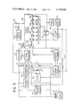
- FIG. 1 is a schematic illustration in block diagram form of the power system of a batter powered vehicle incorporating an illustrative control system for monitoring the state of charge of the battery;
- FIGS. 2 through 6 are schematic illustrations in block diagram form of alternative monitoring systems constructed in accordance with the present invention.
- FIG. 7 is a schematic representation of an alternative threshold detection circuit.
- power is supplied to the system by a battery 1 via mating connectors 3 and 5.
- Connection of the battery to the system couples power to the essential circuits 7 in the system which include all the electrical subsystems in the vehicle that are not to be disabled in response to the detection of a depleted state of charge in the battery.
- Connection of the battery to the system also results in the application of the battery terminal voltage to voltage-dividing resistors 9, 11 and 13 with the result that the magnitudes of the voltages at points 15, 17 and 19 are functions of the magnitude of the voltage present at the output terminals of battery 1.
- the appearance of a voltage at point 15 results in the application of that voltage to sequencer 21.
- the sequencer produces a logical "0" output which is coupled to an AND gate 23 causing it to be disabled and producing a logical "0" output.
- AND gate 23 is disabled in order to make it unresponsive to any transients which may pass through the state of charge detecting circuitry via connectors 3 and 5. After a fixed period of time which may be typically on the order of one second, or as long as is necessary for all transients to subside, the output of the sequencer becomes logical "1".
- Reference voltage source 27 may be any of a number of known circuits which provide constant voltages as outputs even though they may be powered by a source which varies within certain limits. Such circuits are well known and may typically comprise Zener diode regulated voltage sources or the like.
- the voltage sent by reference voltage source 27 to comparator 25 is selected to be equal in magnitude to the voltage present a point 19 when the output terminal voltage of battery 1 is on the order of 10% higher than the nominal terminal voltage of the battery.
- This 10% figure is selected because, for lead acid batteries, the terminal voltage of the battery when it is fully charged is usually about 10% higher than its nominal terminal voltage.
- comparator 25 will detect this condition by comparing the voltage at point 19 to the voltage coupled to the comparator by source 27 and will produce a logical "1" output for a fixed period of time on the order of four seconds, after which the output returns to logical "0". It has been empirically shown that this technique is generally quite reliable.
- the particular value of reference terminal voltage that is used varies as a function of the nominal terminal voltage of the battery and the battery type.
- the logical "1" output of comparator 25 drives one of the inputs of AND gate 23.
- the other input of AND gate 23 is driven by sequencer 21.
- the sequencer changes its output from logical "0" to logical "1” after transients in the system have subsided.
- the presence at the input of AND gate 23 of the logical "1" output of comparator 25, which indicates that the battery is fully charged, and the logical "1" output of sequencer 21, which indicates that transients have subsided, causes the output of AND gate 23 to produce a logical "1” output.
- This logical "1" output is coupled to and drives the "clear" input of a counter 29, thereby clearing any signal that may be in the counter.
- Outputs 29a-g of counter 29 have two digital states “0" and "1” and display the output of counter 29 in binary code with output 29a being the least significant output digit and output 29g the most significant. When the counter is cleared, all of its outputs 29a-g are logical "0", indicating that the battery is fully charged. In a commercial embodiment of the invention counter 29 has 14 binary stages and 7 outputs from the seven most significant bits.
- Outputs 29d and 29g are coupled to a NAND gate 41 whose output drives lockout circuit 43.
- the two logical “0"s at the input of NAND gate cause it to have a logical "1" output.
- This logical "1" output causes lockout circuit 43 to close the contacts 45 of a relay 47 and couples power to the nonessential electrical circuits 49, such as the power lift of an electrical truck.
- output 29g is the most significant output, it will not change to a "1" output until half the total capacity of counter 29 is counted. When this happens, the logical "1" will actuate an alarm 57, notifying the operator.
- NAND gate 41 will not change until more than half the total capacity of counter 29 has been counted when a digital value which includes a logical "1" at outputs 29d and 29g is first reached.
- lockout circuit 43 will open contacts 45, which will remain open, thereby disabling nonessential circuits 49.
- the operator of the vehicle is thus forced to return to the charging station because the nonessential task performing circuits such as the power lift of the vehicle are disabled while essential circuits such as the traction motor are still operable.
- the point at which lockout circuit 43 is activated can be modified simply by selecting the appropriate output leads 29a-g to control NAND gate 41.
- the sum of the time that the magnitude of the battery terminal voltage is below a threshold level is a measure of the state of charge of the battery.
- a picture of its state of charge can be continuously constructed by cumulatively storing the periods of time that the terminal voltage remains below a given threshold.
- a tracking comparator 35 which compares the voltage present at point 17 to a voltage provided to comparator 35 by reference voltage source 27.
- the voltage coupled by reference voltage source 27 to comparator 35 is selected to be approximately equal to the voltage at point 17 when the output terminal voltage of the battery is at the desired threshold.
- this threshold is set to be about 90% to 97% of the rated terminal voltage of a lead acid battery.
- the threshold voltage can be varied to accommodate differences in individual operating conditions.
- the voltage at point 17 is coupled to comparator 35 by a tracking filter 36 which prevents transients and other signals unrelated to depletion in the state of charge of the battery from being registered in the monitoring circuitry. Setting the response of filter 36 to eliminate transients faster than 10 milliseconds to 100 milliseconds has been found to give excellent results, as this effectively eliminates microsecond and millisecond transients which are not related to charge depletion.
- AND gate 37 which is coupled to the clocking input of counter 29, is responsive to the output of tracking comparator 35, to a free-running oscillator 39 and to the output of NAND gate 41.
- oscillator 39 periodically produces a logical "1" pulse, at a pulse repetition rate of approximately 200 milliseconds.
- the output of counter 29 is converted to an analogue signal by summing resistors 51a-g.
- Resistors 51a-g have successively lower values, each resistor having a value of resistance one half that of the previous resistor.
- resistor 51a has a value of R ohms
- resistor 51b a value of R/2 ohms
- resistor 51c a value of R/4 ohms and so forth.
- the current output from resistor 51b is thus twice the current output from resistor 51a, while the current output from resistor 51c is four times the output current from resistor 51a, etc.
- the outputs of the resistors are coupled together and sent to an inverting amplifier 53 which sums them.
- amplifier 53 is an inverting amplifier it has a maximum output when outputs 29a-g are all logical "0". This results in a full scale deflection of meter 31 which is gradually decreased to zero as pulses are stored in counter 29. Because these pulses are periodic and are only coupled from the oscillator during the time that the tracking comparator senses a voltage below threshold, the number of pulses stored is proportional to the total amount of time that tracking comparator 35 has detected a voltage below threshold. Thus, the display on panel meter 31 reveals the state of charge of the battery.
- Depletion of the state of charge in a battery powered systems results in longer and deeper transient voltage reductions in response to transient load conditions.
- In may therefore be desirable to vary the threshold of comparator 35 in response to the integral stored in counter 29.
- it may be desirable to be able to lower the threshold value in response to a lower level of charge in the battery. This may be done by connecting a resistor 53' from the output of amplifier 53 to the input of tracking comparator 35, as is illustrated in phantom lines.
- the extent of the change in threshold is about 7.5% of rated terminal voltage for a lead acid battery.
- the longer and deeper transients in output terminal voltage which occur in response to increasingly lower states of charge in a battery may also be compensated for by making the response of tracking filter 36 a function of the integral stored in counter 29. This may be done using the feedback path, shown in phantom lines in FIG. 1, extending between amplifier 53 and filter 36.
- the amount of feedback to comparator 35 or filter 36 can be varied, for example, by varying the resistance of resistor 53', to adjust for different operating conditions.
- battery 1 may be disconnected from the system and then reconnected.
- a memory battery 79 which supplies power to counter 29 during the interval that the battery 1 is disconnected.
- Memory battery 79 is coupled to counter 29 by diode 81 which is biased into the nonconducting region by diode 83 when battery 1 is connected in the circuit.
- FIG. 2 the preferred embodiment of the apparatus of the present invention is illustrated.
- the operation of this system is largely identical to that of the system illustrated in FIG. 1.
- the primary difference is that oscillator 39 tracking comparator 35 and AND gate 37 have been replaced by tracking comparator 35', self-resetting integrator 39' and AND gate 37'.
- comparator 35' When a voltage below the threshold value is detected by comparator 35', it produces an output current which is fed via diode 61 and variable resistor 63 to capacitor 65.
- the voltage present across the capacitor is applied to terminal 67 of a unijunction transistor 69.
- Terminal 71 of the unijunction transistor is provided with a bias voltage by a voltage divider comprising resistors 73 and 75 which are connected to a source of DC power.
- tracking comparator 35' Whenever the output of tracking comparator 35' becomes active, it sends current into capacitor 65, thereby raising the voltage at terminal 67. This voltage is stored in capacitor 65 after the tracking comparator returns to its unactivated state, and it resumes increasing as soon as tracking comparator 35' is again actuated.
- variable resistor 63 By varying the resistance of variable resistor 63, one can vary the pulse repetition rate of the output signal from terminal 77 of transistor 69. This, in turn, will vary the length of time it takes counter 29 to trigger alarm 57 and lockout circuit 43. Thus, by adjusting resistor 63, the response of the apparatus of FIG. 2 can be modified as necessary to reflect individual operating experience with the battery being monitored.
- FIG. 3 Another embodiment of the invention is illustrated in FIG. 3.
- the apparatus and the operation of this embodiment is substantially the same as that of FIG. 2 but a Schmitt trigger 135 has been substituted for comparator 35' and self-resetting integrator 39' has been eliminated.
- a Schmitt trigger is a comparator which has hysteresis.
- Schmitt trigger 135 switches from a first output state to a second output state when the battery terminal voltage applied to it through tracking filter 36 falls below a threshold value. It remains in this output state until the battery terminal voltage rises above a second threshold level greater than the threshold level which switches the trigger from the first output state to the second state.
- Schmitt trigger is preferred over that of an ordinary comparator to avoid erroneous counts due to noise when the battery terminal voltage is hovering near the threshold value.
- a second threshold level which is a fixed voltage above the first threshold level, spurious counts due to noise can be eliminated.
- Schmitt trigger 135 is applied directly to counter 29 through AND gate 37'.
- the counter registers a count upon detecting the rising edge of the Schmitt trigger output as it switches from its first output state to its second output state.
- this embodiment merely counts the number of times that the battery terminal voltage falls below a threshold level.
- the remainder of the circuit operates in the same fashion as that of FIG. 2 causing activation of an alarm and de-activation of non-essential circuits only after many counts have been accumulated.
- FIG. 4 Still another embodiment of the invention is shown in FIG. 4.
- the apparatus and its operation are similar to that illustrated in FIGS. 2 and 3.
- what is counted is not voltage excursions below a threshold value but rather voltage excursions below a threshold value and having a severity in excess of another threshold value. This is accomplished by substituting a differential amplifier 260, an integrator 265 and a comparator 270 for self-resetting integrator 39' of FIG. 2.
- the output of tracking filter 36 is applied to comparator 35' and to differential amplifier 260.
- Comparator 35' and amplifier 260 compare the battery terminal voltage from filter 36 with the same reference voltage from source 27.
- the output of differential amplifier 260 is a signal proportional to the difference between the reference voltage and the battery terminal voltage.
- the output of the comparator is a signal which disables integrator 265, which would otherwise integrate the output of differential amplifier 260.
- comparator 35' enables integrator 265.
- integrator 265 may be an integrating capacitor and associated circuitry similar, for example, to capacitor 65, diode 61, and variable resistor 63 of FIG. 2.
- Integrator 265 may be enabled, for example, by applying the appropriate signal from comparator 35' to an AND gate or by removing a short across the integrating capacitor or a short on the input signal applied from differential amplifier 260 to integrator 265. The output of the integrator is applied to comparator 270 and the output of comparator 270 is applied to AND Gate 37' and thence to the input to digital counter 29.
- integrator 265 When the battery terminal voltage falls below the threshold voltage applied to comparator 35', integrator 265 is enabled by the signal from comparator 35' and begins to integrate the output signal from differential amplifier 260. The voltage accumulated in integrator 265 is compared with a reference voltage signal in comparator 270. When the capacitor voltage exceeds the reference voltage, comparator 270 switches from a first output state to a second output state. When AND Gate 37' is enabled, this results in the application of a signal to digital counter 29 which illustratively detects the rising edge produced by the change of output states and increments counter 29. The remainder of the circuit operates in the same fashion as that of FIG. 2.
- the voltage stored by integrator 265 is reduced to an initial value.
- comparator 35' may replace the short circuit and empty the charge stored in the integrating capacitor.
- the output signal is applied by comparator 270 to digital counter 29 only if the integral of the particular excursion of battery terminal voltage below threshold is sufficiently great to cause the voltage developed across integrator 265 to exceed the reference voltage applied to comparator 270.
- an output signal is produced by comparator 270, this signal will be terminated when the battery terminal voltage rises above the reference voltage applied to comparator 35' and the voltage stored in integrator 265 is reduced to its initial value.
- This output pulse is triggered by a signal from comparator 35' when it detects that the battery terminal voltage has fallen below the reference voltage.
- a signal is applied to AND gate 37' only when the battery terminal voltage falls below the reference voltage and the integral of the particular excursion of battery terminal voltage below threshold is sufficiently great as to exceed a reference voltage applied to comparator 270 within the duration of the output pulse from one-shot 275.
- FIG. 6 Another alternative embodiment of the invention is illustrated in FIG. 6.
- a battery 310 is connected via connectors 312 and 314 into the vehicle's monitoring system. This causes actuation of a timing circuit 316 which, after a delay typically on the order of one second, actuates comparator 318 for a period also typically on the order of one second. If the voltage present at the output terminals of battery 310 is unusually high in comparison to the nominal terminal voltage, comparator 318 produces a pulse at its output. This pulse serves as an indication to the remaining circuitry in the system that the battery is sufficiently charged.
- the function of comparator 318 and timing circuit 316 is similar to that of sequencer 21 and reset comparator 25 of FIG. 1 and will not be discussed further.
- Reference voltages are provided for comparator 318 and several other elements of the system by a reference voltage circuit 315 that produces reference voltages A, B, C and D using conventional circuitry. As shown reference voltage A is applied to comparator 318.
- An integrator 328 is used to store a signal that is representative of state of charge. Initially, integrator 328 in the vehicle monitoring circuit has an integral stored in it which represents the state of charge of the last battery used in the vehicle. When a new battery is placed into the vehicle, it thus becomes necessary to reset the integrating device.
- comparator 318 senses that an unusually high voltage is present across its input and hence that a new battery has been connected to the system, it sets a bistable circuit (e.g. a flip-flop) 320, whose output is used to set integrating device 328 to zero as will be explained below.
- Bistable 320 also actuates clamp circuit 322 which, through unity gain amplifier 324, causes the display of a full charge indication on meter 326. The clamp circuit thus causes the display of the full charge condition detected by comparator 318 regardless of the integral stored in the integrator. This is required since the integrator may take several minutes to reset, but it is desired to display the fully charged condition of the battery immediately.
- Integrator 328 may comprise any circuit which is capable of integrating electrical information and providing an output signal which is proportional to the integral.
- Such an integrator circuit is shown in Eugene P. Finger and Edward M. Marwell's U.S. patent application Ser. No. 538,466, now U.S. Pat. No. 4,012,681, entitled “Battery Control System for Battery Operated Vehicles” filed Jan. 3, 1975, Edward M. Marwell and Curtis Beusman's U.S. Pat. No. 3,255,413 entitled “Electro-Chemical Coulometer Including Differential Capacitor Measuring Elements” and Eugene P. Finger's U.S. Pat. Nos. 3,704,431 and 3,704,432 entitled “Coulometer Controlled Variable Frequency Generator” and “Capacitive Coulometer Improvements”.
- integration is performed by an electrochemical coulometer which receives current from an electrical signal source, the integral of whose output is indicative of the parameter which one wishes to monitor. Advancement of the coulometer results in changing the length of the mercury columns in the coulometer and consequently the capacitive coupling between the mercury columns and a metallic plate disposed around the body of the coulometer. An oscillator in series with a capacitor is put in parallel with the coulometer, thereby causing an AC voltage to appear on the plate. This electrical voltage is a function of the capacitance between the column of mercury in electrical contact with the capacitor and the plate disposed around the coulometer body.
- This AC voltage present on the plate is then amplified and sent to a simple amplitude detector which produces a DC output proportional to the peak-to-peak value of the AC voltage coupled to the plate.
- this DC voltage is the output of integrator 328. As will be explained below, it is representative of the state of charge of the battery and is coupled to amplifier 324.
- resetting of the integrator is accomplished by passing a current through the coulometer.
- This current is in a direction opposite that of the signal source which advances the coulometer and has a magnitude relatively large compared to the magnitude of the current produced by that signal source. This may most conveniently be done by incorporating an SCR in bistable 320 and passing the output of bistable 320 through the coulometer.
- the value of the integral stored in integrator 328 is sensed by comparator 330 and compared with a value corresponding to full charge voltage as determined by reference voltage B. When the integrator reaches full charge, the comparator resets bistable 320 which, in turn, disables clamp circuit 322. The output of integrator circuit 328 is then free to drive amplifier 324, thereby displaying on meter 326 the integral representative of the state of charge of battery 310 which is stored in the integrator.
- the present invention obtains a signal indicative of the state of charge of a battery by monitoring the magnitude and duration of drops in terminal voltage.
- the magnitude and duration of the decrease in terminal voltage is detected by circuit 332 and an output signal related thereto is applied to the integrator 328.
- Circuit 332 is a circuit which will produce a current at its output which is responsive to the voltage at the battery terminals.
- circuit 332 is actuated to feed a current to integrator 328, thereby advancing integrator 328 so that the voltage level displayed on meter 326 decreases from that indicative of full charge.
- the output of circuit 332 is active only for the time when the voltage is below its threshold value and returns to its inactive state in response to a rise in terminal voltage above that threshold value.
- a particularly advantageous non-linear circuit 332 is illustrated in FIG. 6.
- This device comprises a threshold detector 334 which, when the voltage at the terminals of battery 310 drops below its threshold, produces an electrical signal which advances integrator 328. Further reductions in terminal voltage below successively lower thresholds results in actuation of successive threshold detectors 336 and 338.
- Detectors 334, 336 and 338 are sequentially and individually actuated (i.e., non-cumulatively) in response to voltage reductions with detectors 334, 336 and 338 having, respectively, high, medium and low thresholds and, respectively, high, medium and low outputs. This results in successively reducing the effect on integrator 328 of successively greater reductions in terminal voltage.
- the frequency, duration and magnitude of voltage reductions increase, their increasing magnitude results in a successively decreasing effect on integrator 328.
- detector 334 may produce a constant output once it is actuated, and detectors 336 and 338 may be successively and cumulatively actuated to produce outputs having opposite sense to and lesser but fixed magnitude in comparison to the output of detector 334. Detectors 336 and 338 would thus have the effect of reducing the output of circuit 332 as the magnitude of voltage reductions increases.
- the use of a non-linear display device will also serve the function of linearizing the display.
- the output of integrator 328 When the output of integrator 328 reaches a value corresponding to a first predetermined low state of charge in battery 310 as determined by reference voltage C, it triggers threshold circuit 340 which actuates a low capacity warning light in order to warn the operator of the battery's condition. Further use of the battery with corresponding further reduction in the output of integrator 328 results in the actuation of threshold circuit 342 when the output of the integrator reaches a still lower value determined by reference voltage D. Actuation of circuit 342 removes electricity from nonessential systems on a vehicle such as the lift, thereby leaving the vehicle with power applied only to such essential functions as the traction motor and forcing the operator to return to a central station for a newly charged battery.
- rejector 344 and 346 will be responsive to the output of the integrator to prevent further integration at a point before the limits of integration of integrator 328 are exceeded.
- Rejector circuits 344 and 346 will thus protect integrator 328, during discharge of the battery and resetting of integrator 328, respectively.
- rejectors 344 and 346 may simply take the form of current sources which are activated by threshold circuits to produce at the limits of integration a current opposite in direction to the current which is advancing the electrochemical coulometer.
- Threshold circuit 332' comprises threshold detectors 350a-n that are triggered at a voltage level responsive not only to the voltage present at the output of battery 310 but also to a feedback voltage coupled by resistors 352a-n from the output of integrator 328. Threshold detectors 350a-n advance integrator 328 at a rate proportional to the value of their respective output resistors Ra-n.
- Threshold detectors 350a-n may simply be comparators which change their output at different threshold values which are a function of the voltage fed back from integrator 328 by resistors 352a-n and reference voltages coupled from reference voltage source 315' by resistors 356a-n. For the circuit shown in FIG. 7, detectors 350a-n are successively and cumulatively actuated at different threshold values determined by reference voltage source 315' in a similar fashion as the alternative non-linear circuits 332 of FIG. 6 discussed three paragraphs above.
- comparator 350b couples a current through resistor Rb which is opposite in sense and lower in magnitude than the output of comparator 350a so that as the voltage at the battery terminal becomes lower and comparator 350b is actuated, the output of circuit 332' is reduced and causes a reduction in the rate at which the integrator advances.
- Comparators 350c-n operate in similar fashion with the limitation that the cumulative effect of operation of comparators 350b-n does not exceed the effect of operation of comparator 350a to which they are opposed.
- this circuit is such that as the output of the integrator indicates the storage of an increasingly large integral (and therefore greater depletion of the battery), the output voltage that is fed back by resistor 352a serves to effectively lower the threshold values of the terminal voltage of battery 310 which will cause actuation of threshold detectors 350a-n.
- the thresholds are lowered in order to require greater and greater reductions in terminal voltage to actuate comparators 350a-n.
- This feedback arrangement thus reduces or nullifies the relatively rapid advancement of the integrator that would occur as the battery's charge is increasingly depleted if the threshold of the detector circuit were not varied.
- resistors 352a-n non-linear resistive elements. This may also result in improving the linearity of the output of integrators 328 as an indication of the state of charge.
- the threshold of the threshold circuit may be varied in response to the value stored in the integrator as is done in the embodiment illustrated in FIG. 7 so also may the output of the threshold circuit be varied in response to the output of the integrator. For example, this may be done by using in place of resistors Ra-n photoresistive devices whose resistance changes in response to incident light. The output of integrator 328 may then be made to drive a light source whose light would be made to fall upon the photoresistive devices and thus vary their resistance as the output of integrator 328 is varied. Variation of the resistance of the photoresistive devices results in varying the current output of comparators 350a-n, thereby varying the output of the threshold circuit.
- a plurality of threshold detectors may also be used in the circuits illustrated in FIGS. 1-5 to synthesize any desired response by the selection of various thresholds and various electrical outputs for each of the plurality of threshold detectors.
- a synthesized response can readily be used to charge capacitor 65 of FIG. 2; or apparatus could be provided to apply clocking pulses to the digital counter of FIG. 1 at different rates depending on which threshold detector was activated.
- the feedback circuits shown in FIGS. 6 and 7 can likewise be implemented in the apparatus for FIGS. 1-5 as is indicated by resistor 53' of FIGS. 1-5. In the embodiment of FIG.
- a plurality of Schmitt triggers could be used, each of which has a different threshold value so that the number of pulses produced is a measure of the severity of the voltage reduction.
- one or more threshold detectors could be similar to the devices of FIGS. 1 and 2 which produce a number of output pulses depending on the duration of time the battery terminal voltage is below threshold and other threshold detectors could be like that of FIG. 3 which produces only a single output pulse each time the battery terminal voltage falls below threshold.
- the reference voltage applied to differential amplifier 260 of FIGS. 4 and 5 may have a different value from that applied to comparator 35'.
- Such a voltage may be derived by a separate tap from reference voltage source 27.
- this reference voltage may be modified as the battery is depleted by a feedback voltage from the output of amplifier 53.
- the reference voltage applied to comparator 270 may also be modified by a feedback voltage from the output of amplifier 53.
- FIGS. 1-7 disclose a system in which a threshold circuit produces an intermediate output signal when the magnitude of the battery terminal voltage is less than threshold value. This signal is then integrated over a plurality of different intervals in which the magnitude of the battery terminal voltage is less than the threshold value. The integrated signal provides a first output signal which we have found is a useful measure of the state of charge of the battery.
- the apparatus of our invention may take many forms. Numerous other devices and configurations of components, which are within the scope of our invention, will be apparent to those skilled in the art. All such devices in which an intermediate output signal is produced, directly or indirectly, in connection with a fall in the magnitude of battery terminal voltage to less than a threshold value are intended to be encompassed by the monitoring and signal producing means of the broadest claims. Likewise, unless otherwise indicated, the integrating means of the claims is intended to be read broadly to cover all types of analog and digital integrating devices.
- the intermediate output signal may take many forms. For example, it can be a digital signal or an analog signal. If it is a digital signal, it may be a single event or a plurality of events such as a train of pulses.
- the first output signal which is the integral of the intermediate output signal, may generally be described as a monotonic function of the time that the magnitude of said terminal voltage is below is threshold value. And since the threshold circuit is not activated until the magnitude of the terminal voltage is below a threshold value, the first output signal in the embodiments of FIGS. 1-7 may be described as a function of the magnitude of the terminal voltage. In the embodiments shown in FIGS. 1-5, the magnitude of the intermediate output signal does not vary with the magnitude of the battery terminal voltage provided that magnitude is less than the threshold value. With the particular threshold detectors 334,336, 338 and 350a-n shown in FIGS.
- the output of individual threshold detectors does not vary with the battery terminal voltage applied thereto once the battery terminal voltage falls below threshold and an output signal is produced.
- individual threshold detection circuits can be formed in which the output varies with the difference between the battery terminal voltage and a reference voltage.
- the magnitude of the intermediate output signal does vary as a function of the magnitude of the battery terminal voltage when the battery terminal voltage is below the first threshold value.
- integrator 265 of FIG. 4 is an analogue signal that is the integral of the battery terminal voltage below a threshold value. This signal can be integrated in analogue fashion by applying it directly to an integrator such as integrator 328 of FIG. 6.
- the intermediate output signal from each of the threshold detectors shown in FIG. 7 will be recognized as a function of the difference between the battery terminal voltage and a reference voltage that is a function of the output of integrator 328 and the output of reference source 315'.
- various transfer functions can be synthesized depending on the particular feedback circuitry used. All these modifications are contemplated to be within the scope of the invention.
- the threshold value at which a comparator commences production of the intermediate output signal need not be the same as that at which it stops producing said signal.
- the case of a Schmitt trigger illustrates one example of a system where the threshold value for switching from a first output state to a second is not the same as that for switching from the second state back to the first.
- the threshold value may also be varied during the period that an intermediate output signal is being produced. For example, in those devices in which there is feedback from the integrator the threshold value may vary during the period of time the battery terminal voltage is below it. It may also be advantageous to produce an intermediate output signal which continues for a fixed period of time after the voltage rises above the threshold.
- transient excursions below the threshold value will not be integrated in those circuits that use a filter to eliminate such transients.
Abstract
Description
Claims (129)
Priority Applications (1)
| Application Number | Priority Date | Filing Date | Title |
|---|---|---|---|
| US05/936,725 US4193026A (en) | 1976-04-18 | 1978-08-25 | Method and apparatus for measuring the state of charge of a battery by monitoring reductions in voltage |
Applications Claiming Priority (2)
| Application Number | Priority Date | Filing Date | Title |
|---|---|---|---|
| US67812876A | 1976-04-18 | 1976-04-18 | |
| US05/936,725 US4193026A (en) | 1976-04-18 | 1978-08-25 | Method and apparatus for measuring the state of charge of a battery by monitoring reductions in voltage |
Related Parent Applications (1)
| Application Number | Title | Priority Date | Filing Date |
|---|---|---|---|
| US67812876A Continuation | 1976-04-18 | 1976-04-18 |
Publications (1)
| Publication Number | Publication Date |
|---|---|
| US4193026A true US4193026A (en) | 1980-03-11 |
Family
ID=27101963
Family Applications (1)
| Application Number | Title | Priority Date | Filing Date |
|---|---|---|---|
| US05/936,725 Expired - Lifetime US4193026A (en) | 1976-04-18 | 1978-08-25 | Method and apparatus for measuring the state of charge of a battery by monitoring reductions in voltage |
Country Status (1)
| Country | Link |
|---|---|
| US (1) | US4193026A (en) |
Cited By (74)
| Publication number | Priority date | Publication date | Assignee | Title |
|---|---|---|---|---|
| US4297639A (en) * | 1978-12-13 | 1981-10-27 | Branham Tillman W | Battery testing apparatus with overload protective means |
| US4323849A (en) * | 1980-01-11 | 1982-04-06 | Hybricon, Inc. | Coulometer |
| EP0071439A1 (en) * | 1981-07-23 | 1983-02-09 | Curtis Instruments, Inc. | Quiescent battery testing method and apparatus |
| WO1983000740A1 (en) * | 1981-08-26 | 1983-03-03 | Melocik, Grant, C. | Battery voltage monitoring and indicating apparatus |
| EP0079788A1 (en) * | 1981-11-16 | 1983-05-25 | Curtis Instruments, Inc. | Battery state of charge metering method and apparatus |
| US4388618A (en) * | 1981-01-07 | 1983-06-14 | Curtis Instruments, Inc. | Battery state of charge indicator operating on bidirectional integrations of terminal voltage |
| US4731601A (en) * | 1986-12-08 | 1988-03-15 | General Motors Corporation | Cranking system performance indicator |
| US4827220A (en) * | 1987-10-26 | 1989-05-02 | Intermark Corp. | Method and apparatus for testing batteries |
| US4916438A (en) * | 1987-10-16 | 1990-04-10 | Oneac Corporation | Battery charging, monitoring and alarm circuit |
| US5089762A (en) * | 1986-12-12 | 1992-02-18 | Sloan Jeffrey M | Battery disconnect device |
| US5136620A (en) * | 1990-12-31 | 1992-08-04 | Eaves Stephen S | Battery charge cycle counter |
| US5200877A (en) * | 1990-04-04 | 1993-04-06 | Baton Labs, Inc. | Battery protection system |
| US5284719A (en) * | 1992-07-08 | 1994-02-08 | Benchmarq Microelectronics, Inc. | Method and apparatus for monitoring battery capacity |
| US5298850A (en) * | 1991-03-29 | 1994-03-29 | Yuasa Battery Company Limited | Charge indicator of battery |
| EP0615133A1 (en) * | 1993-03-12 | 1994-09-14 | Globe-Union Inc. | State of charge indicator for a battery |
| US5357203A (en) * | 1992-07-08 | 1994-10-18 | Benchmarq Microelectronics, Inc. | Battery monitoring circuit for operating with high battery discharge rates |
| US5375335A (en) * | 1993-09-16 | 1994-12-27 | Hunter Engineering Company | Battery management for vehicle alignment sensor |
| US5432429A (en) * | 1990-10-23 | 1995-07-11 | Benchmarq Microelectronics, Inc. | System for charging/monitoring batteries for a microprocessor based system |
| US5440221A (en) * | 1992-07-08 | 1995-08-08 | Benchmarg Microelectronics, Inc. | Method and apparatus for monitoring batttery capacity with charge control |
| US5565853A (en) * | 1992-01-27 | 1996-10-15 | Samsung Electronics Co., Ltd. | Function control device managing energy consumption for a mobile system powered by a battery |
| US5565760A (en) * | 1994-11-02 | 1996-10-15 | General Electric Company | Electrical propulsion systems for a golf car |
| US5633592A (en) * | 1992-12-12 | 1997-05-27 | Braun Aktiengesellschaft | Charge status indicator |
| US5698965A (en) * | 1995-12-01 | 1997-12-16 | Flight Systems, Inc. | Apparatus and method for determining the current state of charge of a battery by monitoring battery voltage increases above and decreases below a threshold |
| US5818333A (en) * | 1995-04-25 | 1998-10-06 | Yaffe; Yacob | Device for warning of vehicle battery deterioration |
| US5847566A (en) * | 1994-09-16 | 1998-12-08 | Seiko Epson Corporation | Battery capacity calculation method |
| US5949157A (en) * | 1997-09-11 | 1999-09-07 | Baton Labs, Inc. | Motor driven switch |
| US5973497A (en) * | 1994-10-21 | 1999-10-26 | Braun Aktiengesellschaft | Method of determining and displaying battery charge status |
| USRE36454E (en) * | 1994-11-02 | 1999-12-21 | General Electric Company | Electrical propulsion systems for a vehicle |
| US6252380B1 (en) | 1984-05-21 | 2001-06-26 | Intermec Ip Corp. | Battery pack having memory |
| US6271643B1 (en) | 1986-12-18 | 2001-08-07 | Intermec Ip Corp. | Battery pack having memory |
| US6307349B1 (en) | 2000-02-24 | 2001-10-23 | Intermec Ip Corp. | Battery pack having memory |
| WO2002031791A1 (en) * | 2000-10-06 | 2002-04-18 | Battery Alert Ltd. | Method and device for in-use detecting low cranking strength of a combustion engine battery during engine starting |
| US6377028B1 (en) | 1990-10-23 | 2002-04-23 | Texas Instruments Incorporated | System for charging monitoring batteries for a microprocessor based method |
| US6529840B1 (en) * | 1999-10-26 | 2003-03-04 | Cellon France | Device for estimating the state of charge of a battery |
| US6590396B1 (en) | 1999-01-19 | 2003-07-08 | Battery Alert, Ltd. | Device and method for indicating in-use charging and abnormal discharging of a combustion engine battery following engine turn-off |
| US6704629B2 (en) * | 2001-11-30 | 2004-03-09 | Bppower, Inc. | Device for monitoring motor vehicle's electric power and method therefor |
| US20050046388A1 (en) * | 2003-08-28 | 2005-03-03 | Tate Edward D. | Simple optimal estimator for PbA state of charge |
| US20050125172A1 (en) * | 2003-12-05 | 2005-06-09 | Motorola, Inc. | Method and apparatus for use with a portable power source |
| US20050182306A1 (en) * | 2004-02-17 | 2005-08-18 | Therasense, Inc. | Method and system for providing data communication in continuous glucose monitoring and management system |
| US20050253590A1 (en) * | 2004-05-17 | 2005-11-17 | John Sutherland | Battery charge testing apparatus |
| US20060001429A1 (en) * | 2004-07-02 | 2006-01-05 | Bppower Inc. | Method of monitoring motor vehicle's electric power by comparing internal resistance of battery with a predeterminated warning resistance thereof and apparatus therefor |
| US20060002220A1 (en) * | 2004-07-02 | 2006-01-05 | Seagate Technology Llc | Assessing energy requirements for a refreshed device |
| US20060198225A1 (en) * | 2005-03-04 | 2006-09-07 | Seagate Technology Llc | Reducing power consumption in a data storage system |
| US20070139015A1 (en) * | 2005-12-21 | 2007-06-21 | Se-Wook Seo | Method for compensating state of charge of battery and battery management system using the same |
| US20070139013A1 (en) * | 2005-12-21 | 2007-06-21 | Se-Wook Seo | Method for compensating state of charge of battery and battery management system using the same |
| US20070148532A1 (en) * | 2005-12-22 | 2007-06-28 | Gye-Jong Lim | Method of adjusting SOC for battery and battery management system using the same |
| US20070194791A1 (en) * | 2006-02-17 | 2007-08-23 | Bppower Inc. | Method and apparatus for monitoring the condition of a battery by measuring its internal resistance |
| US20070296421A1 (en) * | 2006-06-07 | 2007-12-27 | Nec Electronics Corporation | Voltage drop measurement circuit |
| US20080007219A1 (en) * | 2006-06-30 | 2008-01-10 | Seagate Technology Llc | Arbitrating battery power calibration in an intelligent storage element |
| US20080214900A1 (en) * | 2007-03-01 | 2008-09-04 | Abbott Diabetes Care, Inc. | Method and apparatus for providing rolling data in communication systems |
| US20080281179A1 (en) * | 2007-05-08 | 2008-11-13 | Abbott Diabetes Care, Inc. | Analyte monitoring system and methods |
| US20080281171A1 (en) * | 2007-05-08 | 2008-11-13 | Abbott Diabetes Care, Inc. | Analyte monitoring system and methods |
| US20080278332A1 (en) * | 2007-05-08 | 2008-11-13 | Abbott Diabetes Care, Inc. | Analyte monitoring system and methods |
| US20090082922A1 (en) * | 2005-04-21 | 2009-03-26 | Continental Teves Ag & Co. Ohg | Motor vehicle equipped with a pneumatic level control system |
| US20090105570A1 (en) * | 2006-03-31 | 2009-04-23 | Abbott Diabetes Care, Inc. | Analyte monitoring devices and methods therefor |
| EP2068161A2 (en) | 2007-07-23 | 2009-06-10 | Yung-Chen Huang | Battery performance monitor |
| US20100309001A1 (en) * | 2003-04-04 | 2010-12-09 | Abbott Diabetes Care Inc. | Method and System for Transferring Analyte Test Data |
| US8112240B2 (en) | 2005-04-29 | 2012-02-07 | Abbott Diabetes Care Inc. | Method and apparatus for providing leak detection in data monitoring and management systems |
| US8149117B2 (en) | 2007-05-08 | 2012-04-03 | Abbott Diabetes Care Inc. | Analyte monitoring system and methods |
| US8362904B2 (en) | 2007-05-08 | 2013-01-29 | Abbott Diabetes Care Inc. | Analyte monitoring system and methods |
| WO2013023189A1 (en) * | 2011-08-11 | 2013-02-14 | Qualcomm Incorporated | Battery monitoring circuit |
| US8456301B2 (en) | 2007-05-08 | 2013-06-04 | Abbott Diabetes Care Inc. | Analyte monitoring system and methods |
| US8512239B2 (en) | 2003-06-10 | 2013-08-20 | Abbott Diabetes Care Inc. | Glucose measuring device for use in personal area network |
| US8576061B2 (en) * | 2008-02-06 | 2013-11-05 | Ford Global Technologies, Llc | System and method for controlling one or more vehicle features based on driver status |
| US8585591B2 (en) | 2005-11-04 | 2013-11-19 | Abbott Diabetes Care Inc. | Method and system for providing basal profile modification in analyte monitoring and management systems |
| US8665091B2 (en) | 2007-05-08 | 2014-03-04 | Abbott Diabetes Care Inc. | Method and device for determining elapsed sensor life |
| US8993331B2 (en) | 2009-08-31 | 2015-03-31 | Abbott Diabetes Care Inc. | Analyte monitoring system and methods for managing power and noise |
| US9226701B2 (en) | 2009-04-28 | 2016-01-05 | Abbott Diabetes Care Inc. | Error detection in critical repeating data in a wireless sensor system |
| US9314195B2 (en) | 2009-08-31 | 2016-04-19 | Abbott Diabetes Care Inc. | Analyte signal processing device and methods |
| US20170269129A1 (en) * | 2014-09-22 | 2017-09-21 | Panduit Corp. | System for the Verification of the Absence of Voltage |
| US20170292984A1 (en) * | 2016-04-07 | 2017-10-12 | Fujitsu Limited | Capacitor life diagnosis apparatus and capacitor life diagnosis method |
| US9968306B2 (en) | 2012-09-17 | 2018-05-15 | Abbott Diabetes Care Inc. | Methods and apparatuses for providing adverse condition notification with enhanced wireless communication range in analyte monitoring systems |
| US9980669B2 (en) | 2011-11-07 | 2018-05-29 | Abbott Diabetes Care Inc. | Analyte monitoring device and methods |
| US11793936B2 (en) | 2009-05-29 | 2023-10-24 | Abbott Diabetes Care Inc. | Medical device antenna systems having external antenna configurations |
Citations (5)
| Publication number | Priority date | Publication date | Assignee | Title |
|---|---|---|---|---|
| US3286253A (en) * | 1964-03-10 | 1966-11-15 | Ca Atomic Energy Ltd | Analog-to-digital encoder |
| GB1207394A (en) * | 1966-10-06 | 1970-09-30 | Norma Gmbh | Electronic circuit arrangement for measuring statistical parameters of stochastical processes |
| GB1247986A (en) * | 1968-06-21 | 1971-09-29 | Bissett Berman Corp | Aircraft service computer |
| GB1262016A (en) * | 1969-10-03 | 1972-02-02 | Electric Power Storage Ltd | Improvements relating to battery condition indicators |
| GB1335072A (en) * | 1970-05-27 | 1973-10-24 | Dequipments Pour La Navigation | Method and apparatus for determining the probability density function and the distribution function of a random variable |
-
1978
- 1978-08-25 US US05/936,725 patent/US4193026A/en not_active Expired - Lifetime
Patent Citations (5)
| Publication number | Priority date | Publication date | Assignee | Title |
|---|---|---|---|---|
| US3286253A (en) * | 1964-03-10 | 1966-11-15 | Ca Atomic Energy Ltd | Analog-to-digital encoder |
| GB1207394A (en) * | 1966-10-06 | 1970-09-30 | Norma Gmbh | Electronic circuit arrangement for measuring statistical parameters of stochastical processes |
| GB1247986A (en) * | 1968-06-21 | 1971-09-29 | Bissett Berman Corp | Aircraft service computer |
| GB1262016A (en) * | 1969-10-03 | 1972-02-02 | Electric Power Storage Ltd | Improvements relating to battery condition indicators |
| GB1335072A (en) * | 1970-05-27 | 1973-10-24 | Dequipments Pour La Navigation | Method and apparatus for determining the probability density function and the distribution function of a random variable |
Cited By (135)
| Publication number | Priority date | Publication date | Assignee | Title |
|---|---|---|---|---|
| US4297639A (en) * | 1978-12-13 | 1981-10-27 | Branham Tillman W | Battery testing apparatus with overload protective means |
| US4323849A (en) * | 1980-01-11 | 1982-04-06 | Hybricon, Inc. | Coulometer |
| US4388618A (en) * | 1981-01-07 | 1983-06-14 | Curtis Instruments, Inc. | Battery state of charge indicator operating on bidirectional integrations of terminal voltage |
| EP0071439A1 (en) * | 1981-07-23 | 1983-02-09 | Curtis Instruments, Inc. | Quiescent battery testing method and apparatus |
| US4460870A (en) * | 1981-07-23 | 1984-07-17 | Curtis Instruments, Inc. | Quiescent voltage sampling battery state of charge meter |
| WO1983000740A1 (en) * | 1981-08-26 | 1983-03-03 | Melocik, Grant, C. | Battery voltage monitoring and indicating apparatus |
| EP0079788A1 (en) * | 1981-11-16 | 1983-05-25 | Curtis Instruments, Inc. | Battery state of charge metering method and apparatus |
| US4560937A (en) * | 1981-11-16 | 1985-12-24 | Curtis Instruments, Inc. | Battery state of charge metering method and apparatus |
| US6252380B1 (en) | 1984-05-21 | 2001-06-26 | Intermec Ip Corp. | Battery pack having memory |
| US4731601A (en) * | 1986-12-08 | 1988-03-15 | General Motors Corporation | Cranking system performance indicator |
| US5089762A (en) * | 1986-12-12 | 1992-02-18 | Sloan Jeffrey M | Battery disconnect device |
| US6271643B1 (en) | 1986-12-18 | 2001-08-07 | Intermec Ip Corp. | Battery pack having memory |
| US4916438A (en) * | 1987-10-16 | 1990-04-10 | Oneac Corporation | Battery charging, monitoring and alarm circuit |
| US4827220A (en) * | 1987-10-26 | 1989-05-02 | Intermark Corp. | Method and apparatus for testing batteries |
| US5200877A (en) * | 1990-04-04 | 1993-04-06 | Baton Labs, Inc. | Battery protection system |
| US5296997A (en) * | 1990-04-04 | 1994-03-22 | Baton Labs, Inc. | System for protecting a battery |
| US5296788A (en) * | 1990-04-04 | 1994-03-22 | Baton Labs, Inc. | System for controlling a motor driven switch |
| US6377028B1 (en) | 1990-10-23 | 2002-04-23 | Texas Instruments Incorporated | System for charging monitoring batteries for a microprocessor based method |
| US5432429A (en) * | 1990-10-23 | 1995-07-11 | Benchmarq Microelectronics, Inc. | System for charging/monitoring batteries for a microprocessor based system |
| US5136620A (en) * | 1990-12-31 | 1992-08-04 | Eaves Stephen S | Battery charge cycle counter |
| US5298850A (en) * | 1991-03-29 | 1994-03-29 | Yuasa Battery Company Limited | Charge indicator of battery |
| US5565853A (en) * | 1992-01-27 | 1996-10-15 | Samsung Electronics Co., Ltd. | Function control device managing energy consumption for a mobile system powered by a battery |
| US5357203A (en) * | 1992-07-08 | 1994-10-18 | Benchmarq Microelectronics, Inc. | Battery monitoring circuit for operating with high battery discharge rates |
| US5284719A (en) * | 1992-07-08 | 1994-02-08 | Benchmarq Microelectronics, Inc. | Method and apparatus for monitoring battery capacity |
| US5440221A (en) * | 1992-07-08 | 1995-08-08 | Benchmarg Microelectronics, Inc. | Method and apparatus for monitoring batttery capacity with charge control |
| US5454710A (en) * | 1992-07-08 | 1995-10-03 | Benchmarg Microelectronics, Inc. | Display system for a battery monitoring circuit |
| US5633592A (en) * | 1992-12-12 | 1997-05-27 | Braun Aktiengesellschaft | Charge status indicator |
| EP0615133A1 (en) * | 1993-03-12 | 1994-09-14 | Globe-Union Inc. | State of charge indicator for a battery |
| US5375335A (en) * | 1993-09-16 | 1994-12-27 | Hunter Engineering Company | Battery management for vehicle alignment sensor |
| US5847566A (en) * | 1994-09-16 | 1998-12-08 | Seiko Epson Corporation | Battery capacity calculation method |
| US5973497A (en) * | 1994-10-21 | 1999-10-26 | Braun Aktiengesellschaft | Method of determining and displaying battery charge status |
| USRE36454E (en) * | 1994-11-02 | 1999-12-21 | General Electric Company | Electrical propulsion systems for a vehicle |
| US5565760A (en) * | 1994-11-02 | 1996-10-15 | General Electric Company | Electrical propulsion systems for a golf car |
| US5818333A (en) * | 1995-04-25 | 1998-10-06 | Yaffe; Yacob | Device for warning of vehicle battery deterioration |
| US5698965A (en) * | 1995-12-01 | 1997-12-16 | Flight Systems, Inc. | Apparatus and method for determining the current state of charge of a battery by monitoring battery voltage increases above and decreases below a threshold |
| US5949157A (en) * | 1997-09-11 | 1999-09-07 | Baton Labs, Inc. | Motor driven switch |
| US6590396B1 (en) | 1999-01-19 | 2003-07-08 | Battery Alert, Ltd. | Device and method for indicating in-use charging and abnormal discharging of a combustion engine battery following engine turn-off |
| US6529840B1 (en) * | 1999-10-26 | 2003-03-04 | Cellon France | Device for estimating the state of charge of a battery |
| US6307349B1 (en) | 2000-02-24 | 2001-10-23 | Intermec Ip Corp. | Battery pack having memory |
| US6646561B1 (en) * | 2000-10-06 | 2003-11-11 | Battery Alert Ltd. | Method and device for in-use detecting low cranking strength of a combustion engine battery during engine starting |
| WO2002031791A1 (en) * | 2000-10-06 | 2002-04-18 | Battery Alert Ltd. | Method and device for in-use detecting low cranking strength of a combustion engine battery during engine starting |
| US6704629B2 (en) * | 2001-11-30 | 2004-03-09 | Bppower, Inc. | Device for monitoring motor vehicle's electric power and method therefor |
| US8437966B2 (en) | 2003-04-04 | 2013-05-07 | Abbott Diabetes Care Inc. | Method and system for transferring analyte test data |
| US8682598B2 (en) | 2003-04-04 | 2014-03-25 | Abbott Laboratories | Method and system for transferring analyte test data |
| US20100309001A1 (en) * | 2003-04-04 | 2010-12-09 | Abbott Diabetes Care Inc. | Method and System for Transferring Analyte Test Data |
| US8560250B2 (en) | 2003-04-04 | 2013-10-15 | Abbott Laboratories | Method and system for transferring analyte test data |
| US8483974B2 (en) | 2003-04-04 | 2013-07-09 | Abbott Diabetes Care Inc. | Method and system for transferring analyte test data |
| US8647269B2 (en) | 2003-06-10 | 2014-02-11 | Abbott Diabetes Care Inc. | Glucose measuring device for use in personal area network |
| US8512239B2 (en) | 2003-06-10 | 2013-08-20 | Abbott Diabetes Care Inc. | Glucose measuring device for use in personal area network |
| US6927554B2 (en) * | 2003-08-28 | 2005-08-09 | General Motors Corporation | Simple optimal estimator for PbA state of charge |
| US20050046388A1 (en) * | 2003-08-28 | 2005-03-03 | Tate Edward D. | Simple optimal estimator for PbA state of charge |
| US6980912B2 (en) * | 2003-12-05 | 2005-12-27 | Motorola, Inc. | Method and apparatus for use with a portable power source |
| CN100446014C (en) * | 2003-12-05 | 2008-12-24 | 摩托罗拉公司 | Method and apparatus for use with a portable power source |
| US20050125172A1 (en) * | 2003-12-05 | 2005-06-09 | Motorola, Inc. | Method and apparatus for use with a portable power source |
| US8771183B2 (en) | 2004-02-17 | 2014-07-08 | Abbott Diabetes Care Inc. | Method and system for providing data communication in continuous glucose monitoring and management system |
| US20050182306A1 (en) * | 2004-02-17 | 2005-08-18 | Therasense, Inc. | Method and system for providing data communication in continuous glucose monitoring and management system |
| US20050253590A1 (en) * | 2004-05-17 | 2005-11-17 | John Sutherland | Battery charge testing apparatus |
| US7321521B2 (en) | 2004-07-02 | 2008-01-22 | Seagate Technology Llc | Assessing energy requirements for a refreshed device |
| US20060001429A1 (en) * | 2004-07-02 | 2006-01-05 | Bppower Inc. | Method of monitoring motor vehicle's electric power by comparing internal resistance of battery with a predeterminated warning resistance thereof and apparatus therefor |
| US20060002220A1 (en) * | 2004-07-02 | 2006-01-05 | Seagate Technology Llc | Assessing energy requirements for a refreshed device |
| US7212006B2 (en) | 2004-07-02 | 2007-05-01 | Bppower, Inc. | Method and apparatus for monitoring the condition of a battery by measuring its internal resistance |
| USRE44009E1 (en) | 2004-07-02 | 2013-02-19 | Seagate Technology Llc | Assessing energy requirements for a refreshed device |
| US20060198225A1 (en) * | 2005-03-04 | 2006-09-07 | Seagate Technology Llc | Reducing power consumption in a data storage system |
| US7177222B2 (en) | 2005-03-04 | 2007-02-13 | Seagate Technology Llc | Reducing power consumption in a data storage system |
| US8219262B2 (en) * | 2005-04-21 | 2012-07-10 | Continental Aktiengesellschaft | Motor vehicle equipped with a pneumatic level control system |
| US20090082922A1 (en) * | 2005-04-21 | 2009-03-26 | Continental Teves Ag & Co. Ohg | Motor vehicle equipped with a pneumatic level control system |
| US8112240B2 (en) | 2005-04-29 | 2012-02-07 | Abbott Diabetes Care Inc. | Method and apparatus for providing leak detection in data monitoring and management systems |
| US11538580B2 (en) | 2005-11-04 | 2022-12-27 | Abbott Diabetes Care Inc. | Method and system for providing basal profile modification in analyte monitoring and management systems |
| US8585591B2 (en) | 2005-11-04 | 2013-11-19 | Abbott Diabetes Care Inc. | Method and system for providing basal profile modification in analyte monitoring and management systems |
| US9323898B2 (en) | 2005-11-04 | 2016-04-26 | Abbott Diabetes Care Inc. | Method and system for providing basal profile modification in analyte monitoring and management systems |
| US9669162B2 (en) | 2005-11-04 | 2017-06-06 | Abbott Diabetes Care Inc. | Method and system for providing basal profile modification in analyte monitoring and management systems |
| US7649338B2 (en) * | 2005-12-21 | 2010-01-19 | Samsung Sdi Co., Ltd. | Method for compensating state of charge of battery and battery management system using the same |
| US7728555B2 (en) | 2005-12-21 | 2010-06-01 | Samsung Sdi Co., Ltd. | Method for compensating state of charge of battery and battery management system using the same |
| US20070139013A1 (en) * | 2005-12-21 | 2007-06-21 | Se-Wook Seo | Method for compensating state of charge of battery and battery management system using the same |
| US20070139015A1 (en) * | 2005-12-21 | 2007-06-21 | Se-Wook Seo | Method for compensating state of charge of battery and battery management system using the same |
| US7982433B2 (en) | 2005-12-22 | 2011-07-19 | Samsung Sdi Co., Ltd. | Method of adjusting SOC for battery and battery management system using the same |
| US20070148532A1 (en) * | 2005-12-22 | 2007-06-28 | Gye-Jong Lim | Method of adjusting SOC for battery and battery management system using the same |
| US7902828B2 (en) | 2006-02-17 | 2011-03-08 | Bppower, Inc. | Method and apparatus for monitoring the condition of a battery by measuring its internal resistance |
| US20070194791A1 (en) * | 2006-02-17 | 2007-08-23 | Bppower Inc. | Method and apparatus for monitoring the condition of a battery by measuring its internal resistance |
| US20090105570A1 (en) * | 2006-03-31 | 2009-04-23 | Abbott Diabetes Care, Inc. | Analyte monitoring devices and methods therefor |
| US8597575B2 (en) | 2006-03-31 | 2013-12-03 | Abbott Diabetes Care Inc. | Analyte monitoring devices and methods therefor |
| US8226891B2 (en) | 2006-03-31 | 2012-07-24 | Abbott Diabetes Care Inc. | Analyte monitoring devices and methods therefor |
| US9625413B2 (en) | 2006-03-31 | 2017-04-18 | Abbott Diabetes Care Inc. | Analyte monitoring devices and methods therefor |
| US9039975B2 (en) | 2006-03-31 | 2015-05-26 | Abbott Diabetes Care Inc. | Analyte monitoring devices and methods therefor |
| US7902844B2 (en) * | 2006-06-07 | 2011-03-08 | Renesas Electronics Corporation | Voltage drop measurement circuit |
| US20070296421A1 (en) * | 2006-06-07 | 2007-12-27 | Nec Electronics Corporation | Voltage drop measurement circuit |
| US20080007219A1 (en) * | 2006-06-30 | 2008-01-10 | Seagate Technology Llc | Arbitrating battery power calibration in an intelligent storage element |
| US8519673B2 (en) | 2006-06-30 | 2013-08-27 | Seagate Technology Llc | Arbitrating battery power calibration in a device that selects a battery power unit from a purality of selectable battery power units |
| US20080214900A1 (en) * | 2007-03-01 | 2008-09-04 | Abbott Diabetes Care, Inc. | Method and apparatus for providing rolling data in communication systems |
| US9095290B2 (en) | 2007-03-01 | 2015-08-04 | Abbott Diabetes Care Inc. | Method and apparatus for providing rolling data in communication systems |
| US8123686B2 (en) * | 2007-03-01 | 2012-02-28 | Abbott Diabetes Care Inc. | Method and apparatus for providing rolling data in communication systems |
| US9801545B2 (en) | 2007-03-01 | 2017-10-31 | Abbott Diabetes Care Inc. | Method and apparatus for providing rolling data in communication systems |
| US20080281171A1 (en) * | 2007-05-08 | 2008-11-13 | Abbott Diabetes Care, Inc. | Analyte monitoring system and methods |
| US8456301B2 (en) | 2007-05-08 | 2013-06-04 | Abbott Diabetes Care Inc. | Analyte monitoring system and methods |
| US20080278332A1 (en) * | 2007-05-08 | 2008-11-13 | Abbott Diabetes Care, Inc. | Analyte monitoring system and methods |
| US8665091B2 (en) | 2007-05-08 | 2014-03-04 | Abbott Diabetes Care Inc. | Method and device for determining elapsed sensor life |
| US9949678B2 (en) | 2007-05-08 | 2018-04-24 | Abbott Diabetes Care Inc. | Method and device for determining elapsed sensor life |
| US20080281179A1 (en) * | 2007-05-08 | 2008-11-13 | Abbott Diabetes Care, Inc. | Analyte monitoring system and methods |
| US10178954B2 (en) | 2007-05-08 | 2019-01-15 | Abbott Diabetes Care Inc. | Analyte monitoring system and methods |
| US9000929B2 (en) | 2007-05-08 | 2015-04-07 | Abbott Diabetes Care Inc. | Analyte monitoring system and methods |
| US9035767B2 (en) | 2007-05-08 | 2015-05-19 | Abbott Diabetes Care Inc. | Analyte monitoring system and methods |
| US11696684B2 (en) | 2007-05-08 | 2023-07-11 | Abbott Diabetes Care Inc. | Analyte monitoring system and methods |
| US10952611B2 (en) | 2007-05-08 | 2021-03-23 | Abbott Diabetes Care Inc. | Analyte monitoring system and methods |
| US8461985B2 (en) | 2007-05-08 | 2013-06-11 | Abbott Diabetes Care Inc. | Analyte monitoring system and methods |
| US9177456B2 (en) | 2007-05-08 | 2015-11-03 | Abbott Diabetes Care Inc. | Analyte monitoring system and methods |
| US8362904B2 (en) | 2007-05-08 | 2013-01-29 | Abbott Diabetes Care Inc. | Analyte monitoring system and methods |
| US9314198B2 (en) | 2007-05-08 | 2016-04-19 | Abbott Diabetes Care Inc. | Analyte monitoring system and methods |
| US10653317B2 (en) | 2007-05-08 | 2020-05-19 | Abbott Diabetes Care Inc. | Analyte monitoring system and methods |
| US8593287B2 (en) | 2007-05-08 | 2013-11-26 | Abbott Diabetes Care Inc. | Analyte monitoring system and methods |
| US9574914B2 (en) | 2007-05-08 | 2017-02-21 | Abbott Diabetes Care Inc. | Method and device for determining elapsed sensor life |
| US8149117B2 (en) | 2007-05-08 | 2012-04-03 | Abbott Diabetes Care Inc. | Analyte monitoring system and methods |
| US9649057B2 (en) | 2007-05-08 | 2017-05-16 | Abbott Diabetes Care Inc. | Analyte monitoring system and methods |
| US7928735B2 (en) | 2007-07-23 | 2011-04-19 | Yung-Sheng Huang | Battery performance monitor |
| EP2068161A2 (en) | 2007-07-23 | 2009-06-10 | Yung-Chen Huang | Battery performance monitor |
| US8576061B2 (en) * | 2008-02-06 | 2013-11-05 | Ford Global Technologies, Llc | System and method for controlling one or more vehicle features based on driver status |
| US9226701B2 (en) | 2009-04-28 | 2016-01-05 | Abbott Diabetes Care Inc. | Error detection in critical repeating data in a wireless sensor system |
| US11793936B2 (en) | 2009-05-29 | 2023-10-24 | Abbott Diabetes Care Inc. | Medical device antenna systems having external antenna configurations |
| US11872370B2 (en) | 2009-05-29 | 2024-01-16 | Abbott Diabetes Care Inc. | Medical device antenna systems having external antenna configurations |
| US8993331B2 (en) | 2009-08-31 | 2015-03-31 | Abbott Diabetes Care Inc. | Analyte monitoring system and methods for managing power and noise |
| US11045147B2 (en) | 2009-08-31 | 2021-06-29 | Abbott Diabetes Care Inc. | Analyte signal processing device and methods |
| US9968302B2 (en) | 2009-08-31 | 2018-05-15 | Abbott Diabetes Care Inc. | Analyte signal processing device and methods |
| US11635332B2 (en) | 2009-08-31 | 2023-04-25 | Abbott Diabetes Care Inc. | Analyte monitoring system and methods for managing power and noise |
| US10429250B2 (en) | 2009-08-31 | 2019-10-01 | Abbott Diabetes Care, Inc. | Analyte monitoring system and methods for managing power and noise |
| US11150145B2 (en) | 2009-08-31 | 2021-10-19 | Abbott Diabetes Care Inc. | Analyte monitoring system and methods for managing power and noise |
| US9314195B2 (en) | 2009-08-31 | 2016-04-19 | Abbott Diabetes Care Inc. | Analyte signal processing device and methods |
| WO2013023189A1 (en) * | 2011-08-11 | 2013-02-14 | Qualcomm Incorporated | Battery monitoring circuit |
| US9075090B2 (en) | 2011-08-11 | 2015-07-07 | Qualcomm Incorporated | Battery monitoring circuit |
| US9980669B2 (en) | 2011-11-07 | 2018-05-29 | Abbott Diabetes Care Inc. | Analyte monitoring device and methods |
| US11612363B2 (en) | 2012-09-17 | 2023-03-28 | Abbott Diabetes Care Inc. | Methods and apparatuses for providing adverse condition notification with enhanced wireless communication range in analyte monitoring systems |
| US9968306B2 (en) | 2012-09-17 | 2018-05-15 | Abbott Diabetes Care Inc. | Methods and apparatuses for providing adverse condition notification with enhanced wireless communication range in analyte monitoring systems |
| US11950936B2 (en) | 2012-09-17 | 2024-04-09 | Abbott Diabetes Care Inc. | Methods and apparatuses for providing adverse condition notification with enhanced wireless communication range in analyte monitoring systems |
| US20170269129A1 (en) * | 2014-09-22 | 2017-09-21 | Panduit Corp. | System for the Verification of the Absence of Voltage |
| US10126335B2 (en) * | 2014-09-22 | 2018-11-13 | Panduit Corp. | System for the verification of the absence of voltage |
| US10627455B2 (en) * | 2016-04-07 | 2020-04-21 | Fujitsu Limited | Capacitor life diagnosis apparatus and capacitor life diagnosis method |
| US20170292984A1 (en) * | 2016-04-07 | 2017-10-12 | Fujitsu Limited | Capacitor life diagnosis apparatus and capacitor life diagnosis method |
Similar Documents
| Publication | Publication Date | Title |
|---|---|---|
| US4193026A (en) | Method and apparatus for measuring the state of charge of a battery by monitoring reductions in voltage | |
| US4746854A (en) | Battery charging system with microprocessor control of voltage and current monitoring and control operations | |
| US4021718A (en) | Battery monitoring apparatus | |
| US4017724A (en) | Apparatus for measuring battery depletion by monitoring reductions in voltage | |
| US5640150A (en) | Resettable state-of-charge indicator for rechargeable batteries | |
| US4918368A (en) | System for charging batteries and measuring capacities and efficiencies thereof | |
| EP0346970B1 (en) | Circuit for measuring capacity of battery | |
| US5372898A (en) | Universal inexpensive battery state-of-charge indicator | |
| EP0079788B1 (en) | Battery state of charge metering method and apparatus | |
| EP0071439B1 (en) | Quiescent battery testing method and apparatus | |
| US4514694A (en) | Quiescent battery testing method and apparatus | |
| US4413221A (en) | Method and circuit for determining battery capacity | |
| US4323849A (en) | Coulometer | |
| JPH08136628A (en) | Device for monitoring capacity of battery | |
| US4151454A (en) | Remaining capacity detector of a battery | |
| US4740754A (en) | Bidirectional battery state-of-charge monitor | |
| US4320334A (en) | Battery state-of-charge indicator | |
| US4258306A (en) | State of battery charge indicator circuit | |
| WO1992015893A1 (en) | Battery charge state indicator | |
| EP1037065B1 (en) | Battery charge monitor for an electronic appliance | |
| US4376266A (en) | Device for the monitoring of peak values of a nonperiodic phenomenon with a low recurrence rate | |
| CA1049614A (en) | Method and apparatus for measuring the state of charge of a battery by monitoring reductions in voltage | |
| US3781677A (en) | Variable rate measuring device | |
| US20040150370A1 (en) | Method for detecting slow and small changes of electrical signals | |
| JP2650505B2 (en) | Battery remaining capacity meter |
Legal Events
| Date | Code | Title | Description |
|---|---|---|---|
| AS | Assignment |
Owner name: BANK OF NEW YORK, AS ADMINISTRATIVE AGENT, THE, NE Free format text: GRANT OF SECURITY INTEREST;ASSIGNOR:CURTIS INSTRUMENTS, INC.;REEL/FRAME:017125/0460 Effective date: 20051216 |
|
| AS | Assignment |
Owner name: THE BANK OF NEW YORK, NEW YORK Free format text: SECURITY INTEREST;ASSIGNOR:CURTIS INSTRUMENTS, INC.;REEL/FRAME:017230/0312 Effective date: 20051216 |
|
| AS | Assignment |
Owner name: TD BANK, N.A., NEW YORK Free format text: SECURITY AGREEMENT;ASSIGNOR:CURTIS INSTRUMENTS, INC.;REEL/FRAME:036151/0428 Effective date: 20150707 |
|
| AS | Assignment |
Owner name: TD BANK, N.A., NEW YORK Free format text: AMENDED AND RESTATED SECURITY AGREEMENT;ASSIGNOR:CURTIS INSTRUMENTS, INC.;REEL/FRAME:050048/0354 Effective date: 20190812 |
|
| AS | Assignment |
Owner name: CURTIS INSTRUMENTS, INC., NEW YORK Free format text: RELEASE BY SECURED PARTY;ASSIGNOR:TD BANK, N.A.;REEL/FRAME:058597/0776 Effective date: 20211222 |