US4185704A - Directional drilling apparatus - Google Patents
Directional drilling apparatus Download PDFInfo
- Publication number
- US4185704A US4185704A US05/902,377 US90237778A US4185704A US 4185704 A US4185704 A US 4185704A US 90237778 A US90237778 A US 90237778A US 4185704 A US4185704 A US 4185704A
- Authority
- US
- United States
- Prior art keywords
- stator housing
- hole
- piston
- thrust member
- sub
- Prior art date
- Legal status (The legal status is an assumption and is not a legal conclusion. Google has not performed a legal analysis and makes no representation as to the accuracy of the status listed.)
- Expired - Lifetime
Links
- 238000005553 drilling Methods 0.000 title claims abstract description 42
- 230000008859 change Effects 0.000 claims abstract description 13
- 239000012530 fluid Substances 0.000 claims description 23
- 230000000694 effects Effects 0.000 claims description 12
- 239000003381 stabilizer Substances 0.000 description 11
- 230000015572 biosynthetic process Effects 0.000 description 2
- 238000005755 formation reaction Methods 0.000 description 2
- 238000005552 hardfacing Methods 0.000 description 2
- 230000004048 modification Effects 0.000 description 2
- 238000012986 modification Methods 0.000 description 2
- 230000009467 reduction Effects 0.000 description 2
- 238000005096 rolling process Methods 0.000 description 2
- UONOETXJSWQNOL-UHFFFAOYSA-N tungsten carbide Chemical compound [W+]#[C-] UONOETXJSWQNOL-UHFFFAOYSA-N 0.000 description 2
- 230000008901 benefit Effects 0.000 description 1
- 239000011248 coating agent Substances 0.000 description 1
- 238000000576 coating method Methods 0.000 description 1
- 238000005520 cutting process Methods 0.000 description 1
- 238000006073 displacement reaction Methods 0.000 description 1
- 230000005484 gravity Effects 0.000 description 1
- 239000000463 material Substances 0.000 description 1
- 230000007246 mechanism Effects 0.000 description 1
- 238000007789 sealing Methods 0.000 description 1
- 230000006641 stabilisation Effects 0.000 description 1
- 238000011105 stabilization Methods 0.000 description 1
- XLYOFNOQVPJJNP-UHFFFAOYSA-N water Substances O XLYOFNOQVPJJNP-UHFFFAOYSA-N 0.000 description 1
Images
Classifications
-
- E—FIXED CONSTRUCTIONS
- E21—EARTH DRILLING; MINING
- E21B—EARTH DRILLING, e.g. DEEP DRILLING; OBTAINING OIL, GAS, WATER, SOLUBLE OR MELTABLE MATERIALS OR A SLURRY OF MINERALS FROM WELLS
- E21B17/00—Drilling rods or pipes; Flexible drill strings; Kellies; Drill collars; Sucker rods; Cables; Casings; Tubings
- E21B17/10—Wear protectors; Centralising devices, e.g. stabilisers
- E21B17/1057—Centralising devices with rollers or with a relatively rotating sleeve
-
- E—FIXED CONSTRUCTIONS
- E21—EARTH DRILLING; MINING
- E21B—EARTH DRILLING, e.g. DEEP DRILLING; OBTAINING OIL, GAS, WATER, SOLUBLE OR MELTABLE MATERIALS OR A SLURRY OF MINERALS FROM WELLS
- E21B17/00—Drilling rods or pipes; Flexible drill strings; Kellies; Drill collars; Sucker rods; Cables; Casings; Tubings
- E21B17/10—Wear protectors; Centralising devices, e.g. stabilisers
- E21B17/1014—Flexible or expansible centering means, e.g. with pistons pressing against the wall of the well
-
- E—FIXED CONSTRUCTIONS
- E21—EARTH DRILLING; MINING
- E21B—EARTH DRILLING, e.g. DEEP DRILLING; OBTAINING OIL, GAS, WATER, SOLUBLE OR MELTABLE MATERIALS OR A SLURRY OF MINERALS FROM WELLS
- E21B7/00—Special methods or apparatus for drilling
- E21B7/04—Directional drilling
- E21B7/06—Deflecting the direction of boreholes
- E21B7/068—Deflecting the direction of boreholes drilled by a down-hole drilling motor
Definitions
- This invention relates to new and useful improvements in earth boring apparatus and more particularly to apparatus for directional drilling in the earth.
- the main forces acting on a drill bit are the pendulum forces of gravity, leeward forces of the drill string, the wedging effect of formation changes and the walking effect of rotation, especially in tricone bits. These forces may be controlled by proper control of the bit weight, stiffening the drill string by using larger drill collars or square drill collars, and by placement of stabilizers in the collar string.
- bit-deflection barrels The use of bit-deflection barrels is known in the prior art, e.g. U.S. Pat. Nos. 3,460,639, 3,298,449 and 3,326,305.
- deflection barrels in association with in-hole motors is known in U.S. Pat. Nos. 2,637,527 and 3,023,821.
- U.S. Pat. No. 4,040,495 discloses a bit deflection apparatus for an inhole drilling motor.
- the prior art referred to above has the disadvantage of either requiring frequent trips of the apparatus or in lacking means to provide a substantial mechanical advantage in application of the bit deflection forces.
- the apparatus includes a stator housing adapted to be connected at one end to a string of drill pipe and having a rotor shaft supported therein and extending from the other end which is adapted to support a rotary drill bit, such as tricone bit, thereon.
- Means is provided on the stator housing which is engagable with one side of the drill hole to provide a fulcrum for changing direction of the drilling apparatus and of the hole being drilled.
- This means is preferably a barrel-shaped stabilizer member of arcuate longitudinal cross section. This member is preferably located adjacent the bit end of the stator housing.
- stator housing moving means preferably consists of a laterally movable thrust member which may be operated mechanically or by application of fluid pressure to move the same laterally to engage the side of the hole and deflect the upper or rearward end of the stator housing.
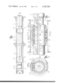
- FIG. 1 is a view in elevation of a directional drilling apparatus that is one preferred embodiment of the invention.
- FIG. 2 is a slightly enlarged view in longitudinal section of the drilling motor deflecting means shown in FIG. 1.
- FIG. 3 is a sectional view taken on the line 3--3 of FIG. 2.
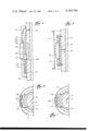
- FIG. 4 is a longitudinal sectional view similar to FIG. 2 of another embodiment of the apparatus.
- FIG. 5 is a longitudinal sectional view similar to FIGS. 2 and 4 of still another embodiment of the drilling motor deflection apparatus.
- FIG. 6 is a sectional view similar to FIG. 3 illustrating another embodiment of drilling motor-deflection thrust member.
- FIG. 7 is a sectional view similar to FIGS. 3 and 6 showing still another embodiment of drilling motor-deflection thrust member.
- an in-hole drilling motor 10 which is connected at its upper end to the lower part of a string of drilling pipe 11 and at its lower end to a rotary drill bit 12, preferably a tricone roller bit.
- the in-hole drilling motor 10 includes stator housing 13 and rotor shaft 14 of any suitable design.
- the in-hole motor 10 is preferably a turbo drill having a system of turbine blades in stator housing 13 and on rotor shaft 14 which cooperate to effect the rotation of rotor shaft 14 when fluid is circulated therethrough.
- the fluid which is circulated through in-hole motor 10 may be water or drilling mud or any other suitable drilling fluid.
- the particular design of in-hole motor 10 is not set forth since any suitable in-hole motor could be used.
- Copending U.S. patent application Ser. No. 849,978, filed Nov. 9, 1977, now abandoned discloses a suitable in-hole drilling motor of the turbo drill type.
- Other in-hole motors such as Moineau motors, positive displacement motors, etc. may be used.
- FIG. 1 the apparatus is shown in position in bore hole 15.
- the stator housing 13 is provided with a suitable means abutting the edge of bore hole 15 to provide a fulcrum for effecting a change in the direction of drilling operation.
- This means consists of a barrel-shaped drill stabilizer 16 carried on stator housing 13.
- Stabilizer 16 has an external surface configuration 17 which is arcuate in longitudinal cross section and is provided with a plurality of grooves 18 which allow for circulation of drilling fluid past the stabilizer.
- Deflection sub 19 consists of tubular member 20 which has a threaded box 21 at its upper end receiving the threaded pin 22 of the lower most member of drill string 11.
- the lower end of tubular member 20 is provided with a threaded pin 23 which fits in the threaded box end 24 of stator housing 13.
- Tubular housing 25 surrounds tubular member 20 and is welded in position as indicated at 26.
- tubular member 25 The inner wall 27 of tubular member 25 is spaced from the outer wall 28 of tubular member 20 and provides an annular chamber 29 therein. Aperture 30 opens from the bore 31 of tubular member 20 into chamber 29 for admission of fluid pressure therein. "O" ring 32 provides a fluid-tight seal at the upper end of housing 25.
- a tubular piston member 33 is slidably positioned on tubular member 20 and slides longitudinally within chamber 29.
- a helical spring 34 is positioned against shoulder 35 at the lower end of tubular member 20 and abuts the lower end of piston 33 to urge the same in an upward or rearward direction. Piston 33 is provided with “O" sealing the same against leakage of fluid.
- Tubular housing 25 is provided with an aperture or window 37 opening into chamber 29 adjacent piston 33.
- a thrust member or pad 38 is positioned in aperture or window 37 and movable laterally of the deflection sub.
- the outer surface 39 of thrust pad 38 is preferably provided with a suitable hard facing such as a coating of tungsten carbide or the like.
- a plurality of pivot or lever members 40 are pivotally supported on piston 33 as indicated at 41 and on thrust pad 38 as indicated at 42.
- Wear plate 43 secured in place by cap screws or the like 44. Wear plate 43 is preferably provided with a surface of suitable hard facing material such as sinerade tungsten carbide.
- drill 11 is rotated by rotation of shaft 14 effected by circulation of drilling fluid through drill string 11 and in-hole motor 10.
- Stabilizer or fulcrum member 16 is of full gauge and slides within the bore of hole 15. Grooves 18 on member 16 allow for circulation of drilling fluid and cuttings back up the hole.
- the deviation sub is substantially in the position shown in FIG. 2.
- Piston 33 is moved to an upper or rearward position by spring 34 and deflection pad or thrust member 38 is moved laterally inward.
- wear pad 43 is positioned away from the bore of hole 15.
- the in-hole motor is operating to rotate drill bit 12 and drill the hole 15 in a relatively straight direction.
- the application of a predetermined pressure of drilling fluid will apply fluid pressure through aperture 30 in the wall of tubular member 23 into the end of chamber 29 above or rearward of piston 33.
- This pressure causes piston 33 to move downward or forward and moves links 40 to force deflection pad or thrust member 38 laterally outward.
- Deflection pad or thrust member 38 engages the wall of hole 15 and as it moves further outward forces the deflection sub to move in the opposite direction until further movement is limited by engagement of wear pad 43 with the opposite side of the bore of hole 15. This amount of movement is indicated by the angle between the arrows at the top of the apparatus in FIG. 1.
- deflection sub 19 causes the upper end of stator housing 13 to be moved as indicated in FIG. 1 and causes the full length of stator housing 13 and rotor shaft 14 to pivot on the fulcrum provided by the full gauge stabilizer member 16. This causes drill bit 12 to be deflected to the left as seen in FIG. 1 and begin to change the direction of the hole toward the left.
- This deflection mechanism can be maintained in an activated position to continue to deflect the drill motor and drill bit to provide for a very substantial deviation in the direction of drilling over an extended period of time.
- the deflection sub can be actuated by variation in the fluid pressure applied to piston 33 it is possible to actuate the deflection sub for a predetermined time of operation and to release the same from the actuated position to permit further drilling operation in a straight undeviated line.
- FIG. 4 there is shown an alternate embodiment of the deflection sub 19.
- the portions of the deflection sub which are the same as in FIGS. 1 to 3 are given the same reference numerals and only the points of modification are given different reference numerals.
- deflection pad or thrust member 38 is provided with internal slot 138 through which the piston 33 extends.
- Piston 33 is provided with a cam surface 133 which engages a matching surface 233 on thrust member 38. Downward or forward movement of piston 33 causes cam surfaces 133 and 233 to effect a positive outward movement of thrust member 38.
- Piston 33 is also provided with cam surface 140 which cooperates with cam surface 240 on thrust member 38 to effect a laterally inward movement of thrust member 38 upon upward or rearward movement of piston 33 upon reduction of the fluid pressure applied thereto.
- FIG. 5 there is shown a still further embodiment in which the deflection pad or thrust member 38 is operated by application of fluid pressure to a flexible diaphragm.
- Tubular member 20 is provided with aperture 30 which supplies fluid pressure to the inside of flexible diaphragm 141 which is positioned in space 29 between housing 25 and tubular member 20. Thrust pad 38 is moved outward or retracted by increase or reduction in fluid pressure applied to rubber or elastometeric diaphragm 141 through aperture 30.
- FIGS. 6 and 7 there are illustrated two further embodiments in which rotary bearing means is provided in the surface of deflection pad or thrust member 38.
- the means for actuation of deflection member or thrust pad 38 may be as shown in FIGS. 2, 4 or 5 or by any other suitable means.
- deflection pad or thrust member 38 is provided will roller bearings 139 supported in the surface thereof. Roller bearings 139 are engagable with the bore or wall of hole 15 upon lateral outward movement of thrust member 38 and provide a rolling contact therewith.
- FIG. 7 a similar modification is shown in which ball bearings 239 are provided in deflection pad or thrust member 38 which similarly provide for a rolling contact with the bore wall of hole 15.
- the embodiments shown in FIGS. 6 and 7 facilitate the downward or forward movement of the in-hole drilling motor while the deflection sub is in a fully actuated position. These bearings reduce the frictional drag on the wall of the bore hole 15 when deflection pad or thrust member 38 is in a fully actuated position.
- any suitable mechanical means may be used for effecting lateral movement of the deflection pad or thrust member 38 in the deflection sub to cause the stator housing and rotor shaft to pivot on fulcrum member or stabilizer 16.
Landscapes
- Engineering & Computer Science (AREA)
- Life Sciences & Earth Sciences (AREA)
- Geology (AREA)
- Mining & Mineral Resources (AREA)
- Physics & Mathematics (AREA)
- Environmental & Geological Engineering (AREA)
- Fluid Mechanics (AREA)
- General Life Sciences & Earth Sciences (AREA)
- Geochemistry & Mineralogy (AREA)
- Mechanical Engineering (AREA)
- Earth Drilling (AREA)
Abstract
Description
Claims (10)
Priority Applications (1)
| Application Number | Priority Date | Filing Date | Title |
|---|---|---|---|
| US05/902,377 US4185704A (en) | 1978-05-03 | 1978-05-03 | Directional drilling apparatus |
Applications Claiming Priority (1)
| Application Number | Priority Date | Filing Date | Title |
|---|---|---|---|
| US05/902,377 US4185704A (en) | 1978-05-03 | 1978-05-03 | Directional drilling apparatus |
Publications (1)
| Publication Number | Publication Date |
|---|---|
| US4185704A true US4185704A (en) | 1980-01-29 |
Family
ID=25415782
Family Applications (1)
| Application Number | Title | Priority Date | Filing Date |
|---|---|---|---|
| US05/902,377 Expired - Lifetime US4185704A (en) | 1978-05-03 | 1978-05-03 | Directional drilling apparatus |
Country Status (1)
| Country | Link |
|---|---|
| US (1) | US4185704A (en) |
Cited By (78)
| Publication number | Priority date | Publication date | Assignee | Title |
|---|---|---|---|---|
| US4406332A (en) * | 1978-10-02 | 1983-09-27 | Dismukes Newton B | Rotary earth boring tool |
| US4442908A (en) * | 1980-07-12 | 1984-04-17 | Preussag Aktiengesellschaft | Tool for drilling curved sections of well holes |
| US4465147A (en) * | 1982-02-02 | 1984-08-14 | Shell Oil Company | Method and means for controlling the course of a bore hole |
| DE3403239C1 (en) * | 1984-01-31 | 1985-06-27 | Christensen, Inc., Salt Lake City, Utah | Devices for optional straight or directional drilling in underground rock formations |
| EP0163946A1 (en) * | 1984-05-12 | 1985-12-11 | Eastman Christensen Company | Apparatus for optional straight or directional drilling underground formations |
| EP0189776A1 (en) * | 1985-01-24 | 1986-08-06 | INTERATOM Gesellschaft mit beschränkter Haftung | Device for measuring vibrations |
| US4623026A (en) * | 1982-06-03 | 1986-11-18 | Kemp Billy W | Method and apparatus of a self-aligning sleeve for the correction of the direction of deviated boreholes |
| WO1987003329A1 (en) * | 1985-12-02 | 1987-06-04 | Drilex Uk Limited | Improvements in directional drilling of a drill string |
| EP0257943A2 (en) * | 1986-08-21 | 1988-03-02 | Smith International (North Sea) Limited | Apparatus having a radially movable member |
| EP0287155A2 (en) * | 1987-04-13 | 1988-10-19 | Shell Internationale Researchmaatschappij B.V. | Assembly for directional drilling of boreholes |
| EP0376805A1 (en) * | 1988-12-30 | 1990-07-04 | Institut Français du Pétrole | Controlled directional drilling assembly with a variable geometry stabiliser, and its use |
| FR2641316A1 (en) * | 1988-12-30 | 1990-07-06 | Inst Francais Du Petrole | CONTROLLED TRACK DRILLING HAVING A VARIABLE-ANGLE ELBOW ELEMENT AND USE THEREOF |
| USRE33751E (en) * | 1985-10-11 | 1991-11-26 | Smith International, Inc. | System and method for controlled directional drilling |
| US5074681A (en) * | 1991-01-15 | 1991-12-24 | Teleco Oilfield Services Inc. | Downhole motor and bearing assembly |
| US5094304A (en) * | 1990-09-24 | 1992-03-10 | Drilex Systems, Inc. | Double bend positive positioning directional drilling system |
| US5099931A (en) * | 1988-02-02 | 1992-03-31 | Eastman Christensen Company | Method and apparatus for optional straight hole drilling or directional drilling in earth formations |
| US5168941A (en) * | 1990-06-01 | 1992-12-08 | Baker Hughes Incorporated | Drilling tool for sinking wells in underground rock formations |
| WO1993011335A1 (en) * | 1991-11-27 | 1993-06-10 | Baroid Technology, Inc. | Downhole adjustable stabilizer and method |
| US5232058A (en) * | 1988-12-30 | 1993-08-03 | Institut Francais Du Petrole | Equipment for a drilling fitting comprising an element to be actuated, a motor and control means |
| US5318138A (en) * | 1992-10-23 | 1994-06-07 | Halliburton Company | Adjustable stabilizer |
| US5318137A (en) * | 1992-10-23 | 1994-06-07 | Halliburton Company | Method and apparatus for adjusting the position of stabilizer blades |
| US5332048A (en) * | 1992-10-23 | 1994-07-26 | Halliburton Company | Method and apparatus for automatic closed loop drilling system |
| US5402856A (en) * | 1993-12-21 | 1995-04-04 | Amoco Corporation | Anti-whirl underreamer |
| US5467834A (en) * | 1994-08-08 | 1995-11-21 | Maverick Tool Company | Method and apparatus for short radius drilling of curved boreholes |
| US5513714A (en) * | 1992-01-31 | 1996-05-07 | Neyrofor-Weir Limited | Stabilization devices for drill motors |
| US5520256A (en) * | 1994-11-01 | 1996-05-28 | Schlumberger Technology Corporation | Articulated directional drilling motor assembly |
| US5542482A (en) * | 1994-11-01 | 1996-08-06 | Schlumberger Technology Corporation | Articulated directional drilling motor assembly |
| EP0770760A1 (en) * | 1995-10-26 | 1997-05-02 | Camco Drilling Group Limited | A drilling assembly for drilling holes in subsurface formations |
| WO1997032110A2 (en) * | 1996-02-28 | 1997-09-04 | Baker Hughes Incorporated | Downhole core sampling and testing apparatus |
| US5727641A (en) * | 1994-11-01 | 1998-03-17 | Schlumberger Technology Corporation | Articulated directional drilling motor assembly |
| US5758723A (en) * | 1996-06-05 | 1998-06-02 | Tiw Corporation | Fluid pressure deactivated thru-tubing centralizer |
| US5785125A (en) * | 1996-10-21 | 1998-07-28 | Tiw Corporation | Mechanical thru-tubing centralizer |
| US6092610A (en) * | 1998-02-05 | 2000-07-25 | Schlumberger Technology Corporation | Actively controlled rotary steerable system and method for drilling wells |
| US6109372A (en) * | 1999-03-15 | 2000-08-29 | Schlumberger Technology Corporation | Rotary steerable well drilling system utilizing hydraulic servo-loop |
| US6158529A (en) * | 1998-12-11 | 2000-12-12 | Schlumberger Technology Corporation | Rotary steerable well drilling system utilizing sliding sleeve |
| WO2001012945A1 (en) * | 1999-08-17 | 2001-02-22 | Halliburton Energy Services, Inc. | Bit connector |
| US6296066B1 (en) | 1997-10-27 | 2001-10-02 | Halliburton Energy Services, Inc. | Well system |
| US6321857B1 (en) * | 1996-06-14 | 2001-11-27 | Andergauge Limited | Directional drilling apparatus and method utilizing eccentric stabilizer |
| US20020185314A1 (en) * | 1998-01-21 | 2002-12-12 | Halliburton Energy Services, Inc. | Anti-rotation device for a steerable rotary drilling device |
| US20030121702A1 (en) * | 2001-12-19 | 2003-07-03 | Geoff Downton | Hybrid Rotary Steerable System |
| US6601658B1 (en) | 1999-11-10 | 2003-08-05 | Schlumberger Wcp Ltd | Control method for use with a steerable drilling system |
| US6609579B2 (en) | 1997-01-30 | 2003-08-26 | Baker Hughes Incorporated | Drilling assembly with a steering device for coiled-tubing operations |
| US20040026128A1 (en) * | 1997-01-30 | 2004-02-12 | Baker Hughes Incorporated | Drilling assembly with a steering device for coiled-tubing operations |
| US6843332B2 (en) | 1997-10-27 | 2005-01-18 | Halliburton Energy Services, Inc. | Three dimensional steerable system and method for steering bit to drill borehole |
| EP1308599A3 (en) * | 1999-07-12 | 2005-04-06 | Halliburton Energy Services, Inc. | Anti-rotation device for a steerable rotary drilling device |
| US20050098353A1 (en) * | 2003-11-07 | 2005-05-12 | Halliburton Energy Services, Inc. | Variable gauge drilling apparatus and method of assembly thereof |
| US20050109542A1 (en) * | 2003-11-26 | 2005-05-26 | Geoff Downton | Steerable drilling system |
| US20050115741A1 (en) * | 1997-10-27 | 2005-06-02 | Halliburton Energy Services, Inc. | Well system |
| US20060157283A1 (en) * | 2005-01-20 | 2006-07-20 | Schlumberger Technology Corporation | Steerable drilling system |
| US7136795B2 (en) | 1999-11-10 | 2006-11-14 | Schlumberger Technology Corporation | Control method for use with a steerable drilling system |
| US7168507B2 (en) | 2002-05-13 | 2007-01-30 | Schlumberger Technology Corporation | Recalibration of downhole sensors |
| US20070261887A1 (en) * | 2006-05-11 | 2007-11-15 | Satish Pai | Steering Systems for Coiled Tubing Drilling |
| US20080041629A1 (en) * | 2003-09-15 | 2008-02-21 | Baker Hughes Incorporated | Steerable bit system assembly and methods |
| US20100071962A1 (en) * | 2008-09-25 | 2010-03-25 | Baker Hughes Incorporated | Drill Bit With Adjustable Steering Pads |
| US20100071956A1 (en) * | 2008-09-25 | 2010-03-25 | Baker Hughes Incorporated | Drill Bit With Adjustable Axial Pad For Controlling Torsional Fluctuations |
| US20100139980A1 (en) * | 2008-12-04 | 2010-06-10 | Fabio Neves | Ball piston steering devices and methods of use |
| US20100212964A1 (en) * | 2009-02-26 | 2010-08-26 | Baker Hughes Incorporated | Drill Bit With Adjustable Cutters |
| US20110031025A1 (en) * | 2009-08-04 | 2011-02-10 | Baker Hughes Incorporated | Drill Bit With An Adjustable Steering Device |
| US8550183B2 (en) | 2008-10-09 | 2013-10-08 | National Oilwell Varco, L.P. | Drilling method |
| WO2014022338A1 (en) * | 2012-07-30 | 2014-02-06 | Baker Hughes Incorporated | Drill bit with a force application device using a lever device for controlling extension of a pad from a drill bit surface |
| CN103821461A (en) * | 2014-03-19 | 2014-05-28 | 中国石油大学(华东) | Fin-type self-rotating anti-eccentric sucker rod |
| US9103175B2 (en) | 2012-07-30 | 2015-08-11 | Baker Hughes Incorporated | Drill bit with hydraulically-activated force application device for controlling depth-of-cut of the drill bit |
| US9181756B2 (en) | 2012-07-30 | 2015-11-10 | Baker Hughes Incorporated | Drill bit with a force application using a motor and screw mechanism for controlling extension of a pad in the drill bit |
| US9255449B2 (en) | 2012-07-30 | 2016-02-09 | Baker Hughes Incorporated | Drill bit with electrohydraulically adjustable pads for controlling depth of cut |
| US9328558B2 (en) | 2013-11-13 | 2016-05-03 | Varel International Ind., L.P. | Coating of the piston for a rotating percussion system in downhole drilling |
| CN105625968A (en) * | 2014-11-06 | 2016-06-01 | 通用电气公司 | Guiding system and guiding method |
| US9404342B2 (en) | 2013-11-13 | 2016-08-02 | Varel International Ind., L.P. | Top mounted choke for percussion tool |
| US9415496B2 (en) | 2013-11-13 | 2016-08-16 | Varel International Ind., L.P. | Double wall flow tube for percussion tool |
| US9500034B2 (en) | 2014-04-17 | 2016-11-22 | Halliburton Energy Services, Inc. | Bottom hole assembly with wearable stabilizer pad for directional steering |
| US9500031B2 (en) | 2012-11-12 | 2016-11-22 | Aps Technology, Inc. | Rotary steerable drilling apparatus |
| US9562392B2 (en) | 2013-11-13 | 2017-02-07 | Varel International Ind., L.P. | Field removable choke for mounting in the piston of a rotary percussion tool |
| US9689209B2 (en) | 2010-12-29 | 2017-06-27 | Nov Downhole Eurasia Limited | Large gauge concentric underreamer |
| US9915138B2 (en) | 2008-09-25 | 2018-03-13 | Baker Hughes, A Ge Company, Llc | Drill bit with hydraulically adjustable axial pad for controlling torsional fluctuations |
| WO2018157218A1 (en) * | 2017-02-28 | 2018-09-07 | Lyomov Shteryo Kostadinov | A continuous wedging tool for directional diamond drilling |
| US20190128071A1 (en) * | 2017-10-29 | 2019-05-02 | Weatherford Technology Holdings, Llc | Rotary Steerable System Having Actuator with Linkage |
| CN111279049A (en) * | 2017-10-29 | 2020-06-12 | 韦特福特科技控股有限责任公司 | Rotary disk valve for rotary guiding tool |
| US11319756B2 (en) * | 2020-08-19 | 2022-05-03 | Saudi Arabian Oil Company | Hybrid reamer and stabilizer |
| US11591860B2 (en) * | 2017-01-05 | 2023-02-28 | Baker Hughes Oilfield Operations Llc | Rotary steerable drilling system with active stabilizer |
Citations (17)
| Publication number | Priority date | Publication date | Assignee | Title |
|---|---|---|---|---|
| US1903467A (en) * | 1929-05-27 | 1933-04-11 | John W Macclatchie | Protector for drill pipe and the like |
| US2014805A (en) * | 1933-05-29 | 1935-09-17 | Frank J Hinderliter | Apparatus for cutting through the side wall of a pipe |
| US2332749A (en) * | 1942-07-11 | 1943-10-26 | Betty Lee Mclaughlin | Tubing anchor |
| US2604365A (en) * | 1947-04-17 | 1952-07-22 | Ralph H Howard | Rubber sleeve protector for drill pipes |
| US2796234A (en) * | 1953-06-08 | 1957-06-18 | William L Mann | Full bore deflection drilling |
| US2874784A (en) * | 1955-10-17 | 1959-02-24 | Baker Oil Tools Inc | Tubing anchor |
| US3023821A (en) * | 1955-03-01 | 1962-03-06 | Walter H Etherington | Well tool |
| US3098534A (en) * | 1960-06-14 | 1963-07-23 | Carr Warren Farrell | Directional drill with hydraulically extended shoe |
| US3370657A (en) * | 1965-10-24 | 1968-02-27 | Trudril Inc | Stabilizer and deflecting tool |
| US3382938A (en) * | 1966-10-03 | 1968-05-14 | Edward B Williams Iii | Drill collar |
| US3528500A (en) * | 1969-02-24 | 1970-09-15 | Joe R Brown | Tubing anchor |
| US3561549A (en) * | 1968-06-07 | 1971-02-09 | Smith Ind International Inc | Slant drilling tools for oil wells |
| US3747700A (en) * | 1971-10-26 | 1973-07-24 | Midway Fishing Tool Co | Oil well mandrel and stabilizing sleeve assembly |
| US3930545A (en) * | 1972-01-21 | 1976-01-06 | St. Joe Minerals Corporation | Tiltable coupling |
| US3933395A (en) * | 1973-12-13 | 1976-01-20 | Reamco, Inc. | Stabilizer |
| US4040495A (en) * | 1975-12-22 | 1977-08-09 | Smith International, Inc. | Drilling apparatus |
| US4101179A (en) * | 1977-10-03 | 1978-07-18 | Royal Tool Company, Inc. | Drilling stabilizer including mechanical interlock device |
-
1978
- 1978-05-03 US US05/902,377 patent/US4185704A/en not_active Expired - Lifetime
Patent Citations (17)
| Publication number | Priority date | Publication date | Assignee | Title |
|---|---|---|---|---|
| US1903467A (en) * | 1929-05-27 | 1933-04-11 | John W Macclatchie | Protector for drill pipe and the like |
| US2014805A (en) * | 1933-05-29 | 1935-09-17 | Frank J Hinderliter | Apparatus for cutting through the side wall of a pipe |
| US2332749A (en) * | 1942-07-11 | 1943-10-26 | Betty Lee Mclaughlin | Tubing anchor |
| US2604365A (en) * | 1947-04-17 | 1952-07-22 | Ralph H Howard | Rubber sleeve protector for drill pipes |
| US2796234A (en) * | 1953-06-08 | 1957-06-18 | William L Mann | Full bore deflection drilling |
| US3023821A (en) * | 1955-03-01 | 1962-03-06 | Walter H Etherington | Well tool |
| US2874784A (en) * | 1955-10-17 | 1959-02-24 | Baker Oil Tools Inc | Tubing anchor |
| US3098534A (en) * | 1960-06-14 | 1963-07-23 | Carr Warren Farrell | Directional drill with hydraulically extended shoe |
| US3370657A (en) * | 1965-10-24 | 1968-02-27 | Trudril Inc | Stabilizer and deflecting tool |
| US3382938A (en) * | 1966-10-03 | 1968-05-14 | Edward B Williams Iii | Drill collar |
| US3561549A (en) * | 1968-06-07 | 1971-02-09 | Smith Ind International Inc | Slant drilling tools for oil wells |
| US3528500A (en) * | 1969-02-24 | 1970-09-15 | Joe R Brown | Tubing anchor |
| US3747700A (en) * | 1971-10-26 | 1973-07-24 | Midway Fishing Tool Co | Oil well mandrel and stabilizing sleeve assembly |
| US3930545A (en) * | 1972-01-21 | 1976-01-06 | St. Joe Minerals Corporation | Tiltable coupling |
| US3933395A (en) * | 1973-12-13 | 1976-01-20 | Reamco, Inc. | Stabilizer |
| US4040495A (en) * | 1975-12-22 | 1977-08-09 | Smith International, Inc. | Drilling apparatus |
| US4101179A (en) * | 1977-10-03 | 1978-07-18 | Royal Tool Company, Inc. | Drilling stabilizer including mechanical interlock device |
Cited By (134)
| Publication number | Priority date | Publication date | Assignee | Title |
|---|---|---|---|---|
| US4406332A (en) * | 1978-10-02 | 1983-09-27 | Dismukes Newton B | Rotary earth boring tool |
| US4442908A (en) * | 1980-07-12 | 1984-04-17 | Preussag Aktiengesellschaft | Tool for drilling curved sections of well holes |
| US4465147A (en) * | 1982-02-02 | 1984-08-14 | Shell Oil Company | Method and means for controlling the course of a bore hole |
| US4623026A (en) * | 1982-06-03 | 1986-11-18 | Kemp Billy W | Method and apparatus of a self-aligning sleeve for the correction of the direction of deviated boreholes |
| DE3403239C1 (en) * | 1984-01-31 | 1985-06-27 | Christensen, Inc., Salt Lake City, Utah | Devices for optional straight or directional drilling in underground rock formations |
| EP0162190A1 (en) * | 1984-01-31 | 1985-11-27 | Eastman Christensen Company | Device for optionally drilling under-ground formations, straight or directionally |
| EP0163946A1 (en) * | 1984-05-12 | 1985-12-11 | Eastman Christensen Company | Apparatus for optional straight or directional drilling underground formations |
| EP0189776A1 (en) * | 1985-01-24 | 1986-08-06 | INTERATOM Gesellschaft mit beschränkter Haftung | Device for measuring vibrations |
| USRE33751E (en) * | 1985-10-11 | 1991-11-26 | Smith International, Inc. | System and method for controlled directional drilling |
| WO1987003329A1 (en) * | 1985-12-02 | 1987-06-04 | Drilex Uk Limited | Improvements in directional drilling of a drill string |
| US4807708A (en) * | 1985-12-02 | 1989-02-28 | Drilex Uk Limited And Eastman Christensen Company | Directional drilling of a drill string |
| EP0257943A2 (en) * | 1986-08-21 | 1988-03-02 | Smith International (North Sea) Limited | Apparatus having a radially movable member |
| EP0257943A3 (en) * | 1986-08-21 | 1989-11-08 | Smith International (North Sea) Limited | Apparatus having a radially movable member |
| EP0287155A2 (en) * | 1987-04-13 | 1988-10-19 | Shell Internationale Researchmaatschappij B.V. | Assembly for directional drilling of boreholes |
| EP0287155A3 (en) * | 1987-04-13 | 1989-11-15 | Shell Internationale Research Maatschappij B.V. | Assembly for directional drilling of boreholes |
| US5099931A (en) * | 1988-02-02 | 1992-03-31 | Eastman Christensen Company | Method and apparatus for optional straight hole drilling or directional drilling in earth formations |
| EP0376805A1 (en) * | 1988-12-30 | 1990-07-04 | Institut Français du Pétrole | Controlled directional drilling assembly with a variable geometry stabiliser, and its use |
| US5316093A (en) * | 1988-12-30 | 1994-05-31 | Institut Francais Du Petrole | Fitting for controlled trajectory drilling, comprising a variable geometry stabilizer and use of this fitting |
| FR2641315A1 (en) * | 1988-12-30 | 1990-07-06 | Inst Francais Du Petrole | CONTROLLED TRACK DRILLING TRIM COMPRISING A VARIABLE GEOMETRY STABILIZER AND USE THEREOF |
| FR2641316A1 (en) * | 1988-12-30 | 1990-07-06 | Inst Francais Du Petrole | CONTROLLED TRACK DRILLING HAVING A VARIABLE-ANGLE ELBOW ELEMENT AND USE THEREOF |
| EP0377373A1 (en) * | 1988-12-30 | 1990-07-11 | Institut Français du Pétrole | Controlled directional drilling assembly with a variable-angle elbow element, and its use |
| US5232058A (en) * | 1988-12-30 | 1993-08-03 | Institut Francais Du Petrole | Equipment for a drilling fitting comprising an element to be actuated, a motor and control means |
| US5168941A (en) * | 1990-06-01 | 1992-12-08 | Baker Hughes Incorporated | Drilling tool for sinking wells in underground rock formations |
| US5094304A (en) * | 1990-09-24 | 1992-03-10 | Drilex Systems, Inc. | Double bend positive positioning directional drilling system |
| US5074681A (en) * | 1991-01-15 | 1991-12-24 | Teleco Oilfield Services Inc. | Downhole motor and bearing assembly |
| WO1993011335A1 (en) * | 1991-11-27 | 1993-06-10 | Baroid Technology, Inc. | Downhole adjustable stabilizer and method |
| US5265684A (en) * | 1991-11-27 | 1993-11-30 | Baroid Technology, Inc. | Downhole adjustable stabilizer and method |
| US5293945A (en) * | 1991-11-27 | 1994-03-15 | Baroid Technology, Inc. | Downhole adjustable stabilizer |
| GB2277111B (en) * | 1991-11-27 | 1995-06-28 | Baroid Technology Inc | Downhole adjustable stabilizer and method |
| GB2277111A (en) * | 1991-11-27 | 1994-10-19 | Baroid Technology Inc | Downhole adjustable stabilizer and method |
| US5513714A (en) * | 1992-01-31 | 1996-05-07 | Neyrofor-Weir Limited | Stabilization devices for drill motors |
| US5318137A (en) * | 1992-10-23 | 1994-06-07 | Halliburton Company | Method and apparatus for adjusting the position of stabilizer blades |
| US5318138A (en) * | 1992-10-23 | 1994-06-07 | Halliburton Company | Adjustable stabilizer |
| US5332048A (en) * | 1992-10-23 | 1994-07-26 | Halliburton Company | Method and apparatus for automatic closed loop drilling system |
| US5402856A (en) * | 1993-12-21 | 1995-04-04 | Amoco Corporation | Anti-whirl underreamer |
| US5467834A (en) * | 1994-08-08 | 1995-11-21 | Maverick Tool Company | Method and apparatus for short radius drilling of curved boreholes |
| US5542482A (en) * | 1994-11-01 | 1996-08-06 | Schlumberger Technology Corporation | Articulated directional drilling motor assembly |
| US5727641A (en) * | 1994-11-01 | 1998-03-17 | Schlumberger Technology Corporation | Articulated directional drilling motor assembly |
| US5520256A (en) * | 1994-11-01 | 1996-05-28 | Schlumberger Technology Corporation | Articulated directional drilling motor assembly |
| AU690334B2 (en) * | 1994-11-01 | 1998-04-23 | Anadrill International, S.A. | Directional drilling |
| AU695052B2 (en) * | 1995-01-23 | 1998-08-06 | Anadrill International, S.A. | Articulated directional drilling motor assembly |
| US5778992A (en) * | 1995-10-26 | 1998-07-14 | Camco Drilling Group Limited Of Hycalog | Drilling assembly for drilling holes in subsurface formations |
| EP0770760A1 (en) * | 1995-10-26 | 1997-05-02 | Camco Drilling Group Limited | A drilling assembly for drilling holes in subsurface formations |
| WO1997032110A3 (en) * | 1996-02-28 | 1997-11-06 | Baker Hughes Inc | Downhole core sampling and testing apparatus |
| WO1997032110A2 (en) * | 1996-02-28 | 1997-09-04 | Baker Hughes Incorporated | Downhole core sampling and testing apparatus |
| US6401840B1 (en) | 1996-02-28 | 2002-06-11 | Baker Hughes Incorporated | Method of extracting and testing a core from a subterranean formation |
| GB2325307A (en) * | 1996-02-28 | 1998-11-18 | Baker Hughes Inc | Downhole core sampling and testing apparatus |
| US5957221A (en) * | 1996-02-28 | 1999-09-28 | Baker Hughes Incorporated | Downhole core sampling and testing apparatus |
| GB2325307B (en) * | 1996-02-28 | 2000-05-10 | Baker Hughes Inc | Downhole core sampling and testing apparatus |
| US6148933A (en) * | 1996-02-28 | 2000-11-21 | Baker Hughes Incorporated | Steering device for bottomhole drilling assemblies |
| US5758723A (en) * | 1996-06-05 | 1998-06-02 | Tiw Corporation | Fluid pressure deactivated thru-tubing centralizer |
| US6321857B1 (en) * | 1996-06-14 | 2001-11-27 | Andergauge Limited | Directional drilling apparatus and method utilizing eccentric stabilizer |
| US5785125A (en) * | 1996-10-21 | 1998-07-28 | Tiw Corporation | Mechanical thru-tubing centralizer |
| US7028789B2 (en) | 1997-01-30 | 2006-04-18 | Baker Hughes Incorporated | Drilling assembly with a steering device for coiled-tubing operations |
| US20040026128A1 (en) * | 1997-01-30 | 2004-02-12 | Baker Hughes Incorporated | Drilling assembly with a steering device for coiled-tubing operations |
| US6609579B2 (en) | 1997-01-30 | 2003-08-26 | Baker Hughes Incorporated | Drilling assembly with a steering device for coiled-tubing operations |
| US6863137B2 (en) | 1997-10-27 | 2005-03-08 | Halliburton Energy Services, Inc. | Well system |
| US20050098350A1 (en) * | 1997-10-27 | 2005-05-12 | Halliburton Energy Services, Inc. | Three dimensional steering system and method for steering bit to drill borehole |
| US6296066B1 (en) | 1997-10-27 | 2001-10-02 | Halliburton Energy Services, Inc. | Well system |
| US7195083B2 (en) | 1997-10-27 | 2007-03-27 | Halliburton Energy Services, Inc | Three dimensional steering system and method for steering bit to drill borehole |
| US7172038B2 (en) | 1997-10-27 | 2007-02-06 | Halliburton Energy Services, Inc. | Well system |
| US6923273B2 (en) | 1997-10-27 | 2005-08-02 | Halliburton Energy Services, Inc. | Well system |
| US6843332B2 (en) | 1997-10-27 | 2005-01-18 | Halliburton Energy Services, Inc. | Three dimensional steerable system and method for steering bit to drill borehole |
| US20050115741A1 (en) * | 1997-10-27 | 2005-06-02 | Halliburton Energy Services, Inc. | Well system |
| US6325162B1 (en) * | 1997-12-04 | 2001-12-04 | Halliburton Energy Services, Inc. | Bit connector |
| US20020185314A1 (en) * | 1998-01-21 | 2002-12-12 | Halliburton Energy Services, Inc. | Anti-rotation device for a steerable rotary drilling device |
| US7306058B2 (en) | 1998-01-21 | 2007-12-11 | Halliburton Energy Services, Inc. | Anti-rotation device for a steerable rotary drilling device |
| US6092610A (en) * | 1998-02-05 | 2000-07-25 | Schlumberger Technology Corporation | Actively controlled rotary steerable system and method for drilling wells |
| US6158529A (en) * | 1998-12-11 | 2000-12-12 | Schlumberger Technology Corporation | Rotary steerable well drilling system utilizing sliding sleeve |
| US6109372A (en) * | 1999-03-15 | 2000-08-29 | Schlumberger Technology Corporation | Rotary steerable well drilling system utilizing hydraulic servo-loop |
| EP1308599A3 (en) * | 1999-07-12 | 2005-04-06 | Halliburton Energy Services, Inc. | Anti-rotation device for a steerable rotary drilling device |
| WO2001012945A1 (en) * | 1999-08-17 | 2001-02-22 | Halliburton Energy Services, Inc. | Bit connector |
| US7136795B2 (en) | 1999-11-10 | 2006-11-14 | Schlumberger Technology Corporation | Control method for use with a steerable drilling system |
| US6601658B1 (en) | 1999-11-10 | 2003-08-05 | Schlumberger Wcp Ltd | Control method for use with a steerable drilling system |
| US20030127252A1 (en) * | 2001-12-19 | 2003-07-10 | Geoff Downton | Motor Driven Hybrid Rotary Steerable System |
| US7188685B2 (en) | 2001-12-19 | 2007-03-13 | Schlumberge Technology Corporation | Hybrid rotary steerable system |
| US20030121702A1 (en) * | 2001-12-19 | 2003-07-03 | Geoff Downton | Hybrid Rotary Steerable System |
| US7168507B2 (en) | 2002-05-13 | 2007-01-30 | Schlumberger Technology Corporation | Recalibration of downhole sensors |
| US20080041629A1 (en) * | 2003-09-15 | 2008-02-21 | Baker Hughes Incorporated | Steerable bit system assembly and methods |
| US7931098B2 (en) | 2003-09-15 | 2011-04-26 | Baker Hughes Incorporated | Steerable bit system assembly and methods |
| US7802637B2 (en) | 2003-09-15 | 2010-09-28 | Baker Hughes Incorporated | Steerable bit system assembly and methods |
| US20080053705A1 (en) * | 2003-09-15 | 2008-03-06 | Baker Hughes Incorporated | Steerable bit system assembly and methods |
| US20050098353A1 (en) * | 2003-11-07 | 2005-05-12 | Halliburton Energy Services, Inc. | Variable gauge drilling apparatus and method of assembly thereof |
| US7188689B2 (en) | 2003-11-07 | 2007-03-13 | Halliburton Energy Services, Inc. | Variable gauge drilling apparatus and method of assembly therefor |
| GB2408526B (en) * | 2003-11-26 | 2007-10-17 | Schlumberger Holdings | Steerable drilling system |
| US8893824B2 (en) | 2003-11-26 | 2014-11-25 | Schlumberger Technology Corporation | Steerable drilling system |
| US8011452B2 (en) | 2003-11-26 | 2011-09-06 | Schlumberger Technology Corporation | Steerable drilling system |
| US20050109542A1 (en) * | 2003-11-26 | 2005-05-26 | Geoff Downton | Steerable drilling system |
| US20060157283A1 (en) * | 2005-01-20 | 2006-07-20 | Schlumberger Technology Corporation | Steerable drilling system |
| US20070261887A1 (en) * | 2006-05-11 | 2007-11-15 | Satish Pai | Steering Systems for Coiled Tubing Drilling |
| US8408333B2 (en) | 2006-05-11 | 2013-04-02 | Schlumberger Technology Corporation | Steer systems for coiled tubing drilling and method of use |
| US7971662B2 (en) | 2008-09-25 | 2011-07-05 | Baker Hughes Incorporated | Drill bit with adjustable steering pads |
| US9915138B2 (en) | 2008-09-25 | 2018-03-13 | Baker Hughes, A Ge Company, Llc | Drill bit with hydraulically adjustable axial pad for controlling torsional fluctuations |
| US20100071962A1 (en) * | 2008-09-25 | 2010-03-25 | Baker Hughes Incorporated | Drill Bit With Adjustable Steering Pads |
| US8205686B2 (en) | 2008-09-25 | 2012-06-26 | Baker Hughes Incorporated | Drill bit with adjustable axial pad for controlling torsional fluctuations |
| US10001005B2 (en) | 2008-09-25 | 2018-06-19 | Baker Hughes, A Ge Company, Llc | Drill bit with hydraulically adjustable axial pad for controlling torsional fluctuations |
| US20100071956A1 (en) * | 2008-09-25 | 2010-03-25 | Baker Hughes Incorporated | Drill Bit With Adjustable Axial Pad For Controlling Torsional Fluctuations |
| US8550183B2 (en) | 2008-10-09 | 2013-10-08 | National Oilwell Varco, L.P. | Drilling method |
| US20100139980A1 (en) * | 2008-12-04 | 2010-06-10 | Fabio Neves | Ball piston steering devices and methods of use |
| US8157024B2 (en) | 2008-12-04 | 2012-04-17 | Schlumberger Technology Corporation | Ball piston steering devices and methods of use |
| US8474552B2 (en) | 2008-12-04 | 2013-07-02 | Schlumberger Technology Corporation | Piston devices and methods of use |
| US20100212964A1 (en) * | 2009-02-26 | 2010-08-26 | Baker Hughes Incorporated | Drill Bit With Adjustable Cutters |
| US8061455B2 (en) | 2009-02-26 | 2011-11-22 | Baker Hughes Incorporated | Drill bit with adjustable cutters |
| US8087479B2 (en) | 2009-08-04 | 2012-01-03 | Baker Hughes Incorporated | Drill bit with an adjustable steering device |
| US8240399B2 (en) | 2009-08-04 | 2012-08-14 | Baker Hughes Incorporated | Drill bit with an adjustable steering device |
| EP2462307A4 (en) * | 2009-08-04 | 2016-08-17 | Baker Hughes Inc | Drill bit with an adjustable steering device |
| US20110147089A1 (en) * | 2009-08-04 | 2011-06-23 | Baker Hughes Incorporated | Drill bit with an adjustable steering device |
| US20110031025A1 (en) * | 2009-08-04 | 2011-02-10 | Baker Hughes Incorporated | Drill Bit With An Adjustable Steering Device |
| US9689209B2 (en) | 2010-12-29 | 2017-06-27 | Nov Downhole Eurasia Limited | Large gauge concentric underreamer |
| WO2014022338A1 (en) * | 2012-07-30 | 2014-02-06 | Baker Hughes Incorporated | Drill bit with a force application device using a lever device for controlling extension of a pad from a drill bit surface |
| US9103175B2 (en) | 2012-07-30 | 2015-08-11 | Baker Hughes Incorporated | Drill bit with hydraulically-activated force application device for controlling depth-of-cut of the drill bit |
| US9140074B2 (en) | 2012-07-30 | 2015-09-22 | Baker Hughes Incorporated | Drill bit with a force application device using a lever device for controlling extension of a pad from a drill bit surface |
| US9181756B2 (en) | 2012-07-30 | 2015-11-10 | Baker Hughes Incorporated | Drill bit with a force application using a motor and screw mechanism for controlling extension of a pad in the drill bit |
| US9255449B2 (en) | 2012-07-30 | 2016-02-09 | Baker Hughes Incorporated | Drill bit with electrohydraulically adjustable pads for controlling depth of cut |
| US9500031B2 (en) | 2012-11-12 | 2016-11-22 | Aps Technology, Inc. | Rotary steerable drilling apparatus |
| US9328558B2 (en) | 2013-11-13 | 2016-05-03 | Varel International Ind., L.P. | Coating of the piston for a rotating percussion system in downhole drilling |
| US9404342B2 (en) | 2013-11-13 | 2016-08-02 | Varel International Ind., L.P. | Top mounted choke for percussion tool |
| US9562392B2 (en) | 2013-11-13 | 2017-02-07 | Varel International Ind., L.P. | Field removable choke for mounting in the piston of a rotary percussion tool |
| US9415496B2 (en) | 2013-11-13 | 2016-08-16 | Varel International Ind., L.P. | Double wall flow tube for percussion tool |
| CN103821461B (en) * | 2014-03-19 | 2016-02-10 | 中国石油大学(华东) | Fin formula spinning eccentric wear prevention pumping rod |
| CN103821461A (en) * | 2014-03-19 | 2014-05-28 | 中国石油大学(华东) | Fin-type self-rotating anti-eccentric sucker rod |
| US9500034B2 (en) | 2014-04-17 | 2016-11-22 | Halliburton Energy Services, Inc. | Bottom hole assembly with wearable stabilizer pad for directional steering |
| US10550643B2 (en) | 2014-11-06 | 2020-02-04 | Baker Hughes Oilfield Operations Llc | Steering system and method |
| CN105625968A (en) * | 2014-11-06 | 2016-06-01 | 通用电气公司 | Guiding system and guiding method |
| CN105625968B (en) * | 2014-11-06 | 2018-04-13 | 通用电气公司 | Guidance system and guidance method |
| US11591860B2 (en) * | 2017-01-05 | 2023-02-28 | Baker Hughes Oilfield Operations Llc | Rotary steerable drilling system with active stabilizer |
| WO2018157218A1 (en) * | 2017-02-28 | 2018-09-07 | Lyomov Shteryo Kostadinov | A continuous wedging tool for directional diamond drilling |
| WO2019083621A1 (en) * | 2017-10-29 | 2019-05-02 | Weatherford Technology Holdings, Llc | Rotary steerable system having actuator with linkage |
| CN111279049A (en) * | 2017-10-29 | 2020-06-12 | 韦特福特科技控股有限责任公司 | Rotary disk valve for rotary guiding tool |
| CN111295497A (en) * | 2017-10-29 | 2020-06-16 | 韦特福特科技控股有限责任公司 | Rotary guide system with actuator having link |
| US10683702B2 (en) * | 2017-10-29 | 2020-06-16 | Weatherford Technology Holdings, Llc | Rotary steerable system having actuator with linkage |
| CN111295497B (en) * | 2017-10-29 | 2023-02-28 | 韦特福特科技控股有限责任公司 | Rotary guide system with actuator having link |
| US20190128071A1 (en) * | 2017-10-29 | 2019-05-02 | Weatherford Technology Holdings, Llc | Rotary Steerable System Having Actuator with Linkage |
| US11319756B2 (en) * | 2020-08-19 | 2022-05-03 | Saudi Arabian Oil Company | Hybrid reamer and stabilizer |
Similar Documents
| Publication | Publication Date | Title |
|---|---|---|
| US4185704A (en) | Directional drilling apparatus | |
| US4991668A (en) | Controlled directional drilling system and method | |
| US6321857B1 (en) | Directional drilling apparatus and method utilizing eccentric stabilizer | |
| US7234544B2 (en) | Drill tool shaft-to-housing locking device | |
| EP0497422B1 (en) | Downhole adjustable stabilizer | |
| RU2740390C2 (en) | Device for directional drilling with automatic adjustment and a method for directional drilling | |
| US4485879A (en) | Downhole motor and method for directional drilling of boreholes | |
| US4319649A (en) | Stabilizer | |
| US8590636B2 (en) | Rotary steerable drilling system | |
| US9366087B2 (en) | High dogleg steerable tool | |
| US7188685B2 (en) | Hybrid rotary steerable system | |
| EP0594419B1 (en) | Adjustable blade stabilizer for drilling system | |
| US4076084A (en) | Oriented drilling tool | |
| RU2703067C2 (en) | Control layout of direction of movement for directional drilling of well shaft | |
| WO1988003222A1 (en) | Apparatus for controlling the operation of a downhole tool | |
| US20010052428A1 (en) | Steerable drilling tool | |
| US11591860B2 (en) | Rotary steerable drilling system with active stabilizer | |
| US20200318437A1 (en) | Simple Rotary Steerable Drilling System | |
| US4844180A (en) | Downhole drilling motor | |
| US8176999B2 (en) | Steerable drill bit arrangement | |
| AU599093C (en) | Apparatus for controlling the operation of a downhole tool |
Legal Events
| Date | Code | Title | Description |
|---|---|---|---|
| AS | Assignment |
Owner name: BECHTEL INVESTMENTS, INC., NEVADA Free format text: ASSIGNMENT OF 1/2 OF ASSIGNORS INTEREST;ASSIGNOR:MAUER ENGINEERING, INC.,;REEL/FRAME:005091/0626 Effective date: 19880502 Owner name: BECFIELD HORIZONTAL DRILLING SERVICES COMPANY, A Free format text: ASSIGNMENT OF 1/2 OF ASSIGNORS INTEREST;ASSIGNOR:BECHTEL INVESTMENTS;REEL/FRAME:005091/0629 Effective date: 19890412 |
|
| AS | Assignment |
Owner name: BLACK WARRIOR WIRELINE CORP., MISSISSIPPI Free format text: ASSIGNMENT OF ASSIGNORS INTEREST;ASSIGNOR:PHOENIX DRILLING SERVICES, INC.;REEL/FRAME:010078/0656 Effective date: 19980316 |
|
| AS | Assignment |
Owner name: FLEET CAPITAL CORPORATION, TEXAS Free format text: SECURITY INTEREST;ASSIGNOR:BLACK WARRIOR WIRELINE CORP.;REEL/FRAME:009781/0784 Effective date: 19980316 |
|
| AS | Assignment |
Owner name: BLACK WARRIOR WIRELINE CORP., MISSISSIPPI Free format text: RELEASE;ASSIGNOR:FLEET CAPITAL CORPORATION;REEL/FRAME:010572/0514 Effective date: 20000215 |
|
| AS | Assignment |
Owner name: GENERAL ELECTRIC CAPITAL CORPORATION, AS AGENT, CO Free format text: SECURITY AGREEMENT;ASSIGNOR:BLACK WARRIOR WIRELINE CORP.;REEL/FRAME:011958/0442 Effective date: 20010914 |