US4147152A - Projectile propulsion and control in a gas-powered gun - Google Patents
Projectile propulsion and control in a gas-powered gun Download PDFInfo
- Publication number
- US4147152A US4147152A US05/803,353 US80335377A US4147152A US 4147152 A US4147152 A US 4147152A US 80335377 A US80335377 A US 80335377A US 4147152 A US4147152 A US 4147152A
- Authority
- US
- United States
- Prior art keywords
- projectile
- gas
- actuator
- movement
- pawl
- Prior art date
- Legal status (The legal status is an assumption and is not a legal conclusion. Google has not performed a legal analysis and makes no representation as to the accuracy of the status listed.)
- Expired - Lifetime
Links
Images


Classifications
-
- F—MECHANICAL ENGINEERING; LIGHTING; HEATING; WEAPONS; BLASTING
- F41—WEAPONS
- F41B—WEAPONS FOR PROJECTING MISSILES WITHOUT USE OF EXPLOSIVE OR COMBUSTIBLE PROPELLANT CHARGE; WEAPONS NOT OTHERWISE PROVIDED FOR
- F41B11/00—Compressed-gas guns, e.g. air guns; Steam guns
- F41B11/70—Details not provided for in F41B11/50 or F41B11/60
- F41B11/72—Valves; Arrangement of valves
- F41B11/723—Valves; Arrangement of valves for controlling gas pressure for firing the projectile only
Definitions
- This invention relates to guns of the type that are operated by compressed gas such as, for example, CO 2 . It will become apparent, however, that the principles of the present invention are not limited to any one specific type of gas and, indeed, may be applied to a broad spectrum of projectile propulsion mediums.
- this invention relates to ways of increasing the operating efficiency of such guns, with special attention to the manner in which the projectile-propelling charge of gas is treated once it leaves the gas storage chamber therefor.
- one important object of the present invention is to move the projectile rearwardly in the gun along with the structure that unseats the valve so that the gas expansion space defined between the valve and the rear of the projectile will be decreased by such movement prior to firing, hence, reducing the amount of gas expanding energy not used for projectile propulsion.
- Another important object of this invention is to remove any retentive force on the projectile after a predetermined amount of such rearward movement so that the energy of the expanding gas need not be used to overcome any projectile-holding forces and may, instead, be devoted totally to propelling the projectile from the gun.
- a further important object of this invention is to minimize the increase in gas expansion space caused by return forward movement of the valve-actuating structure as it vacates the expansion chamber by terminating such forward movement at a point substantially short of the forward limit of travel for such structure.
- a still further important object of the invention is to obtain the foregoing objectives through structures and mechanisms that permit utilization of an axially reciprocable barrel to permit attainment of benefits derived from that type of construction, e.g., operating simplicity, reliability and manufacturing ease.
- FIG. 1 is a side elevational view in partial cross section of a pistol-type gas-operated gun, with parts removed, in a cocked ready-to-fire position;
- FIG. 2 is an exploded perspective view of the receiver and valve assembly portion of the gun
- FIG. 3 is an exploded perspective view of the handle-trigger-sear portion of the gun
- FIG. 4 is a perspective view of the barrel assembly portion of the gun
- FIG. 5 is an enlarged top plan view of the cocking lever for the gun
- FIG. 6 is a fragmentary, longitudinal cross-sectional view of the gun
- FIG. 7 is a transverse cross-sectional view taken along line 7--7 of FIG. 1;
- FIG. 8 is a transverse cross-sectional view taken along line 8--8 of FIG. 1;
- FIG. 9 is a transverse cross-sectional view taken along line 9--9 of FIG. 1;
- FIG. 10 is an enlarged, fragmentary, detail view of the firing chamber portion of the gun in an initial, projectile-retaining stage of a firing cycle
- FIG. 11 is an enlarged, fragmentary, detail view of the valve assembly and firing chamber portions of the gun in a second, projectile-releasing stage of the firing cycle subsequent to FIG. 10;
- FIG. 12 is an enlarged, fragmentary, detail view of the firing chamber portion of the gun in the releasing position of FIG. 11;
- FIG. 13 is an enlarged, fragmentary, detail view of the firing chamber portion of the gun in a third stage of the firing cycle subsequent to FIGS. 11 and 12;
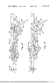
- FIG. 14 is a side elevational view of parts of the gun in a fourth stage of the firing cycle subsequent to FIG. 13;
- FIG. 15 is a side elevational view similar to FIG. 14 but in an initial position preparatory to loading and cocking;
- FIG. 16 is a side elevational view similar to FIG. 15 but in a forwardmost loading position
- FIG. 17 is an enlarged cross-sectional view of the front end portion of the gun showing an alternative embodiment thereof including velicity adjustment means in a minimum velocity position;
- FIG. 18 is another cross-sectional view of the embodiment of FIG. 17 in a maximum velocity position.
- a gas-operated pistol comprising a metallic receiver assembly 10, including a pair of mating elongated side housing members 11, 12 and a handle member 13 adapted to internally mount a removable and replaceable compressed gas container (not shown) on a container seat means 15.
- the receiver assembly provides a trigger guard portion 16 for a sear means 17 and a trigger means 18; a barrel housing portion 20 for mounting a reciprocable barrel means assembly 22 having a valve-actuating stem means 23 at the rear thereof; a cocking and latching means member 24 pivotally mounted thereon; and a valve and valve-operating mechanism housing portion 25 for mounting a valve block assembly 26 having a support tube 28 fixedly secured therein.
- the foregoing components associated with propulsion of the projectile and control of the gas used in such propulsion all lie along a common longitudinal axis for "in-line" operation.
- the valve block assembly 26 comprises an elongated valve block member 30 having an upper portion 31 of generally cylindrical cross section and a lower downwardly extending flange portion 32.
- An elongated central passage 33, FIG. 11, is formed in upper portion 31 by a series of aligned coaxial counterbore portions 34, 36, 38, 40, providing, respectively, an elongated annular mounting and support chamber for support tube 28, an annular barrel means receiving and guide chamber for barrel means 22, an annular valve stem means receiving and guide chamber for valve-actuating stem means 23, and an annular valve-receiving and pressure-holding chamber 41.
- a movable valve means 46 in the form of a ball valve member, is movably mounted in the bore 40 and normally held in sealing engagement with the rear surface of valve seat member 42 by a compression spring member 48 supported in a retaining chamber 50 in an end plug member 52 threadably mounted in the rear end of bore 40 against a sealing ring member 54.
- An axially extending slot 56 and a forwardly downwardly inclined gas passage 58 connect bore 40 to a gas inlet chamber 60 provided in flange portion 32 of the valve block member 30 in which a conventional container connecting and puncturing assembly 61 is threadably sealably mounted.
- valve block assembly 26 is mounted between side plate members 11, 12 by a front hub portion 62 and a rear hub portion 63 having threaded bores located therein to receive threaded fasteners 65 extending through corresponding hub portions and bores 66, 67 in the side plate member 12.
- An internally threaded boss 64 (FIG. 2) on block assembly 26 receives another fastener 65 (FIG. 1) to secure member 11 in place.
- the valve block assembly is mounted on the handle member 13 by a threaded fastener 68 extending through a threaded bore in a hub portion 69 on member 13, FIG. 3, and received in a threaded bore 70 in a hub portion 71 on the lower end of flange portion 32, FIG. 2.
- barrel means assembly 22 comprises an elongated tubular member 72 having a barrel bore 73 for guiding a projectile 74, such as a BB, from the gun through an opening 75 in an annular end cap member 76 in which the front end portion of the member 72 is located in a forward cocked position shown in FIGS. 1 and 6.
- the front end of the member 72 may be rounded and the opening 75 formed by a rearwardly outwardly tapered bore 78 facilitating reciprocable movement of the member 72 relative to the member 76 while maintaining clearance therebetween.
- An operating block member 80 is fixedly mounted on an intermediate portion of member 72 by an elongated forwardly extending cylindrical sleeve portion 82 and a central enlarged cylindrical portion 84 which provide an elongated support bore 86.
- a compression-operating spring 88 is mounted circumjacent member 72 in a spring chamber 90 formed by receiver wall portions 92, 94, FIG. 7, with the forward end of the spring abutting the rear surface of member 76 and the rear end of the spring abutting a shoulder 96 connecting sleeve portion 82 and enlarged portion 84.
- a flange portion 98 extends downwardly and rearwardly from portion 84 with a hub portion 99, FIG.
- a rearward portion 103 of the flange portion 98 extends beyond the rear end of enlarged portion 84 and has arcuate wing portions 104, 106, FIG. 8, connected thereto to provide an elongated rearwardly extending semi-annular surface 108 radially spaced from the outer surface 110 of tube member 28.
- a downwardly facing rear slot 112 at the rear end of flange portion 103 provides a rearwardly facing transverse abutment surface 114 and a forwardly facing inclined cam surface 116.
- the flange portion 103 terminates in a rearwardly facing transverse abutment surface 118.
- the rear end portion of barrel member 72 is closely slidably guidably received in a bore 120 in support tube member 28 which bore generally corresponds in diameter with valve block bore 36.
- the rear end portion of support tube member 28 is fixedly sealably mounted in valve block bore 34 against abutment surface 122, FIG. 11, and supported therewithin in forwardly extending cantilever fashion.
- the outside diameter of the rear end portion of barrel member 72 and the inside diameter of bores 36, 120 are substantially equal with the tolerances being such as to enable substantially friction-free relative sliding movement while at the same time effectively sealing the barrel bore 73 relative to the inside surfaces of bores 36, 120 in the firing position of FIG. 11.
- Actuating stem means 23, FIGS. 4 and 11, comprises an elongated plate member of rectangular cross section having a width substantially the same as the inside diameter of bore 73 of tube member 72 to enable short side surfaces thereof to be fixedly abuttingly mounted on the inside surface of the tube member by suitable fastening means such as welding.
- Stem member 23 is mounted coaxially with the central axis of bore 73, and its outer surfaces cooperate with the internal surface of member 72 to define upper and lower semi-annular gas passages 130, 132.
- the transverse front end surface 134 of member 23 provides a waiting station for a loaded projectile 74
- the transverse rear end surface 136 provides rearwardly facing ball-engaging surface means for centrally impacting the ball 46 and moving the same rearwardly against the bias of spring 48 to enable a gas charge from bore 40 to freely flow through the overall passage defined by bores 38, 44, 36 and passages 130, 132 to the projectile 74.
- the bore 36 is rearwardly inwardly tapered so that at the rear end thereof the outside diameter of tube member 72 is approximately equal to the diameter of bore 36 to substantially confine gas flow to a direct path between passage 38 and passages 130, 132.
- a projectile-retaining means, 160 in the form of a formed wire spring member is mounted in an elongated axially extending opening or slot 162 in the bottom rear end wall portion of member 72 for axial movement with member 72 and radial movement relative to member 72 between a projectile-retaining position, FIG. 10, and a projectile-releasing position, FIG. 12.
- An upwardly radially inwardly extending rear leg portion 164 of member 160 extends through a hole 166 in member 23 with terminal portion 167 rearwardly turned into passage 130 so as to be radially and pivotally displaceably retained in hole 166.
- An upwardly inwardly forwardly extending curved front tip 168 with a rearwardly facing, curved, projectile-engaging surface 169 has a forwardly and downwardly facing, curved cam follower surface 170.
- Both the tip 168 and follower 170 comprise parts of a fore-and-aft extending leg portion 172 of retainer 160, such leg portion 172 having a lower elongated support surface 174 slidably engageable with the radially adjacent portion 176 of the surface of bore 120 of member 28 in the retaining position.
- a rounded connecting surface portion 178 of leg portion 172 is slidably engageable with the radially adjacent portion 179 of a surface 180 in an elongated void 182 in bore 33 of member 31 in the releasing position.
- the leg portion 172 extends parallel to surface 176 with surface 174 supported thereby.
- the curved tip 168 extends into bore 73 to locate curved surface 169 in front of the BB-type projectile 74, thereby confining the projectile in bore 73 between surface 169 and the front side surface 134 of member 23.
- Releasing structure for the retainer 160 is defined by the surface 176 and void 182.
- the rearwardly facing surface 186 of hole 166 of member 23 fully engages the forwardly facing surface 188 of portion 164 of retainer 160 to transfer rearwardly directed force therebetween.
- the retainer 160 pivots downwardly by gravity until surface 178 engages surface portion 179 whereat surface 169 is located completely below bore 73 in slot 162.
- the surface 169 clears the bore 73 prior to the time that surface 178 engages surface 179.
- retainer 160 is pivotally supported by substantially line contact between the rear surface of terminal portion 167 and the upper rear edge 190 of rear surface 191 of hole 166 and between the rear curved connecting surface 192 and the rear surface 194 of slot 162 at 196.
- the trigger means 18 is pivotally mounted in a slot 200 by a pin 202 extending between lug portions 204, 206 on the handle member 13.
- a tension spring 208 is connected to a rearwardly extending flange portion 210 of the trigger member at 212 whereby rearward pivotal movement of the trigger member on pin 202, caused by finger applied pressure on trigger surface 214, elongates spring 208 to cause return forward movement of the trigger member when trigger pull force is removed.
- a flat upwardly facing rib portion 216 extends along the upper part of flange portion 210 and terminates forwardly in a curved cam surface 218.
- a conventional safety means assembly 220, FIG. 6, is mounted in the handle member 16 and associated with the trigger member.
- the sear means 17 comprises an elongated channel-shaped sear member 230 having side wall portions 232, 234 and a connecting web portion 236 pivotally mounted on pin member 202 independently of the trigger member 18 for movement between a holding position, FIGS. 1 and 2, and a released firing position, FIG. 14.
- Tension spring means 238 are connected to a rearwardly downwardly extending flange portion 240 of sear member 230 at 242 to bias the sear member toward the holding position.
- the lower surface 244, FIG. 16, of web portion 236 is supported on the upper surface 246 of flange portion 216 of trigger member 18 rearwardly of pivot 202 and held thereagainst by spring 238.
- the forward end of sear member 230 has a transverse abutment surface portion 230a engageable with the rear surface 118 of rib portion 103 of block member 80.
- the barrel latching and cocking means 24 comprises a member 250 having an elongated generally axially forwardly extending pawl 252, pivotally movable with member 250 about axis 253 of pin 102 between an upwardly displaced released firing and cocking position, FIGS. 1, 2 and 4, and a downwardly displaced barrel latching position, FIG. 14, for terminating forward movement of the barrel means 72.
- An elongated generally downwardly extending cocking lever arm 254 is pivotally movable with member 250 about pin axis 253.
- the pawl 252 has laterally outwardly extending lugs 256, 258 at the forward end with flat parallel upper and lower surfaces 260, 262 connected by a curved cam surface 264.
- the barrel 72 and block member 80 move rearwardly and carry the member 252 rearwardly beyond abutment surface 274 whereupon the lugs 256, 258 of pawl 252 are free to move downwardly by gravity into slot portions 276 onto spaced surfaces 277 by pivotal movement of member 252 about pivot pin 102. Thereafter, forward movement of the barrel member 72 is stopped by engagement of surface 264 with surface 274.
- lever 254 which has lug portions 278, 279 located downwardly beyond slot 272, is rocked forwardly by hand to disengage surfaces 264, 274 by pivotal upward movement until pawl 252 is realigned above surfaces 266.
- the center of gravity of the member 252 is located below the axis 103, or, in other words, on the abutment 270 side of an imaginary line drawn parallel to the path of forward travel of axis 103 and intersecting the same.
- the inertia is such that pawl 252 will be swung counterclockwise into position to strike the abutment 274, notwithstanding the fact that the gun might be on its side and, thus, negate the effects of gravity on pawl 252.
- projectile storage means 280 in the form of a cavity adapted to hold a relatively large number of projectiles therewithin, is provided above the valve housing assembly 26 and extends axially from a single-file loading passage means 282 to a loading opening 284 covered by a suitable displaceable closure 286.
- the forward portion 288 of passage 282 is downwardly curved and an upwardly inclined lip 290 on assembly 26 cooperates therewith to facilitate loading and retention of a projectile above a loading port 292 in tube member 28 adjacent a shoulder 293 on the front end of assembly 26.
- a loading port 294 in barrel member 72 is aligned with loading port 292 to permit a projectile to be transferred by gravity into the firing chamber in barrel bore 73.
- an alternative and presently preferred adjustable operating spring means arrangement is shown to comprise an end tube member 300 threadably adjustably mounted in a threaded bore portion 302 with an abutment flange portion 304 engageable with spring 88 and being movable in an annular slot 306 between a forward minimum projectile velocity position, FIG. 17, and a rearward maximum projectile velocity position, FIG. 18.
- a central bore 308 in member 300 slidably receives the front end 310 of barrel member 72 in all adjusted positions of member 310 which enable selection of varying projectile velocities between the minimum and maximum velocity positions.
- a compressed gas storage container (not shown) is mounted in the handle portion 13 on seat means 15 (FIG. 1) with a gas outlet passage in sealed communication with inlet chamber 60, passages 56 and 58, and bore 40 which is sealed by ball valve 46 and cap member 52, FIG. 11.
- the projectile storage slot 280, FIG. 6, is filled with projectiles and a projectile may be partially located in opening 292 against shoulder 293 by slight tilting of the gun.
- spring 88 is effective to move the barrel assembly rearwardly until surface 118 abuts surface 230a with loading opening 294 axially rearwardly offset from loading opening 292 to complete the cocking cycle with the gun mechanism in a cocked ready-to-fire position as shown in FIGS. 1 and 6.
- the surface 118 will engage surface 230a to prevent rearward movement of the barrel assembly to the valve-opening position.
- the gun When the safety 220 is manually moved to the firing position, the gun may be fired by rearward pulling force on trigger 18 against the bias of the trigger spring 208.
- the trigger flange portion 216 moves upwardly, the front end of sear member 230 is pivoted downwardly against the bias of spring 238 to cause disengagement of abutment surfaces 118, 230a, whereupon the compression spring 88 is effective to rapidly drive the barrel assembly 22 rearwardly with spring 238 being effective to hold sear member 230 against the bottom surface of flange portion 103 for relative sliding engagement therebetween.
- the rearward upward pivotal movement of the trigger and sear is limited by engagement with the bottom surface of the valve housing assembly 26 at 322, FIG. 14. As shown in FIG.
- the ball valve is quickly closed to reseal bore 40 with the barrel assembly being quickly moved forwardly a relatively small distance sufficiently to retract the rear end surface 136 of stem member 23 from restraining engagement with the ball valve in bore 44, the bias of the spring 88 in the rearwardly extended position being insufficient to interfere with the required forward movement of the barrel assembly to quickly close the valve.
- the force available to drive the barrel assembly rearwardly is the primary factor that determines the length of time of opening of passage 44, the amount of compressed gas released and, hence, the velocity of the projectile.
- Efficiency is further enhanced by the manner in which the ball 46 is unseated, and by the way that the charge is treated upon such unseating of the ball 46.
- gas in the chamber 41 has a substantially unrestricted and largely rectilinear line of travel to the back of the projectile 74.
- the charge issuing from the chamber 41 moves easily around the unseated ball 46 without being forced to turn any right angle corners or to backtrack in order to reach the outlet 44, such lack of tortuous movement being unique to this gun construction as compared to those of the prior art.
- the relatively large diameter outlet 44 has little, if any, restrictive effect on the gas, and the straight longitudinal surfaces of the stem 23 present no restrictions to the smooth flow of gas to the projectile 74.
- the gas charge in the gun of the present invention is allowed to flow in straight line, substantially unencumbered fashion to the projectile 74 so that its available energy is used to propel the latter from the gun instead of to simply reach the projectile.
- Improving efficiency in the above manner also has the effect of upgrading performance in that the shooter is assured of essentially constant velocity and trajectory on the projectile each and every time he shoots.
- Such precision and efficiency are further enhanced by virtue of the fact that the projectile 74 is shifted rearwardly with the stem 23 by the retainer 160 during actuation of the valve ball 46.
- the projectile 74 is shifted rearwardly with the stem 23 by the retainer 160 during actuation of the valve ball 46.
- the retainer 160 offers no power-robbing resistance that must be overcome by the expanding gas in order to propel the projectile from the gun. Inasmuch as the retainer 160 releases the projectile 74 prior to the gas acting upon the latter, all of the energies of the gas can be devoted to moving the projectile.
- the role of the cocking and latching means 24 is also of substantial significance. Note that because the barrel 72 is effectively located between a pair of oppositely acting sources of spring power (spring 88 on the one hand, and valve spring 48 on the other), there would be a tendency for the barrel 72 to simply oscillate in rebounding fashion between such two springs absent some way to dissipate or terminate the oscillations. Consequently, even though the projectile may have long since left the gun, the barrel 72 might still be oscillating and the stem 23 repeatedly unseating the ball 46 to allow the escape of additional gas charges.
- Terminating forward movement of the barrel 72 through the use of the pawl 252 in this manner is significant also from the standpoint of decreasing the volume of the gas expansion space behind the projectile 74 during the firing process.
- the rear end portion of the barrel 72 does inherently occupy a certain amount of space within the flow path for the gas charge from chamber 41 to the projectile. Consequently, any movement of such structure out of that area only increases the available volume for the gas to expand, thereby reducing the energy that is available to act against the projectile. It follows, then, that by terminating forward movement of the barrel 72 substantially short of its full extent of forward travel the volume of the expansion space behind the projectile is correspondingly held to a minimum. Thus, the efficiency of the gun and its predictability of performance are significantly enhanced.
Abstract
Description
Claims (26)
Priority Applications (1)
| Application Number | Priority Date | Filing Date | Title |
|---|---|---|---|
| US05/803,353 US4147152A (en) | 1977-06-03 | 1977-06-03 | Projectile propulsion and control in a gas-powered gun |
Applications Claiming Priority (1)
| Application Number | Priority Date | Filing Date | Title |
|---|---|---|---|
| US05/803,353 US4147152A (en) | 1977-06-03 | 1977-06-03 | Projectile propulsion and control in a gas-powered gun |
Publications (1)
| Publication Number | Publication Date |
|---|---|
| US4147152A true US4147152A (en) | 1979-04-03 |
Family
ID=25186319
Family Applications (1)
| Application Number | Title | Priority Date | Filing Date |
|---|---|---|---|
| US05/803,353 Expired - Lifetime US4147152A (en) | 1977-06-03 | 1977-06-03 | Projectile propulsion and control in a gas-powered gun |
Country Status (1)
| Country | Link |
|---|---|
| US (1) | US4147152A (en) |
Cited By (28)
| Publication number | Priority date | Publication date | Assignee | Title |
|---|---|---|---|---|
| US4501085A (en) * | 1981-12-31 | 1985-02-26 | Barnes Lant I | Casting rod |
| US4531503A (en) * | 1984-02-21 | 1985-07-30 | Shepherd Robert G | Fluid pressure repeating pistol with unitary barrel and hammer assembly |
| US4674470A (en) * | 1985-01-29 | 1987-06-23 | Yugengaisha Asahi Shouji | Gas gun with radially enlargeable O-ring |
| JPS6438488U (en) * | 1987-08-27 | 1989-03-08 | ||
| US5174807A (en) * | 1991-03-15 | 1992-12-29 | Macdonald Christopher N | Plant eradication method |
| US5349938A (en) * | 1993-04-22 | 1994-09-27 | Farrell Kenneth R | Reciprocatable barrel pneumatic gun |
| US5586545A (en) * | 1995-10-02 | 1996-12-24 | Mccaslin; John A. | Compressed gas gun |
| WO1997000417A1 (en) * | 1995-06-02 | 1997-01-03 | Joint-Stock Company 'firm 'anics' | Repeat action gas cartridge pistol for firing spherical rounds |
| US5711286A (en) * | 1995-06-02 | 1998-01-27 | Anics Corp. | Gas-powered repeating pistol |
| US5722383A (en) * | 1995-12-01 | 1998-03-03 | Tippmann Pneumatics, Inc. | Impeder for a gun firing mechanism with ammunition feeder and mode selector |
| WO1998023911A1 (en) * | 1996-11-27 | 1998-06-04 | Bsa Guns (Uk) Limited | Gas supply regulator for an air gun |
| WO2001067023A1 (en) | 2000-03-09 | 2001-09-13 | Alexei Lvovich Petrosyan | Multi-charge gas-cylinder pistol |
| US6467473B1 (en) | 1999-02-26 | 2002-10-22 | Airgun Designs, Inc. | Paintball feeders |
| WO2002090864A1 (en) * | 2001-05-08 | 2002-11-14 | Yuri Lazarev | Pneumatic pistol |
| US6488019B2 (en) | 1999-02-26 | 2002-12-03 | Thomas G. Kotsiopoulos | Feeder for a paintball gun |
| US6609511B2 (en) | 1999-02-26 | 2003-08-26 | Airgun Designs, Inc. | Conveyor feed apparatus for a paintball gun |
| US6736125B2 (en) | 2000-12-13 | 2004-05-18 | Zakrytoe aktsionernoe obshchestvo Gruop “ANICS” | Magazine for bullet pneumatic arms and case for said bullet magazine of a pneumatic arm |
| US20060124118A1 (en) * | 2004-07-16 | 2006-06-15 | National Paintball Supply, Inc. | Variable pneumatic sear for paintball gun |
| US20060162716A1 (en) * | 2004-07-16 | 2006-07-27 | National Paintball Supply, Inc. | Gas governor, snatch grip, and link pin for paintball gun |
| US20080265057A1 (en) * | 2007-04-26 | 2008-10-30 | Phillip John Martin | Handheld device and method for clearing obstructions from spray nozzles |
| EP2065668A1 (en) * | 2007-11-29 | 2009-06-03 | Maruzen Company Limited | Air gun |
| US20090277436A1 (en) * | 2008-05-08 | 2009-11-12 | Wilson Wei | Continuous firing type trigger structure for toy gun |
| US7617816B1 (en) | 2006-09-11 | 2009-11-17 | Orr Jeffrey G | Low pressure ram assembly |
| US20100263652A1 (en) * | 2007-01-19 | 2010-10-21 | Maruzen Company Limited | Air gun |
| EP2287553A1 (en) * | 2009-08-18 | 2011-02-23 | Guay Guay Trading Co., Ltd. | Assembly Structure of an Action and a Gas Cylinder |
| US7921837B2 (en) | 2004-07-16 | 2011-04-12 | Kee Action Sports I Llc | Gas governor, snatch grip, and link pin for paintball gun |
| WO2015026702A1 (en) * | 2013-08-19 | 2015-02-26 | Serpent Rural Sports Llc | Elastic projectile propulsion systems and methods |
| EP3173728A1 (en) | 2015-11-30 | 2017-05-31 | Maruzen Company Limited | Threadless air gun valve |
Citations (5)
| Publication number | Priority date | Publication date | Assignee | Title |
|---|---|---|---|---|
| GB190814447A (en) * | 1908-07-08 | 1909-03-25 | Joseph Frederick Bramwell | Improvements in Apparatus for Holding Objects for the Purpose of their being Used as Drawing Copies and the like. |
| US2322212A (en) * | 1942-07-03 | 1943-06-22 | William H Allen | Practice sheel |
| US2980096A (en) * | 1959-01-12 | 1961-04-18 | Crosman Arms Company Inc | Gas powered revolver |
| US3233600A (en) * | 1962-09-04 | 1966-02-08 | Benjamin Air Rifle Company | Gas charged repeater gun |
| US3788298A (en) * | 1972-06-19 | 1974-01-29 | Victor Comptometer Corp | Compressed gas gun with trigger operated hammer release latching structure |
-
1977
- 1977-06-03 US US05/803,353 patent/US4147152A/en not_active Expired - Lifetime
Patent Citations (5)
| Publication number | Priority date | Publication date | Assignee | Title |
|---|---|---|---|---|
| GB190814447A (en) * | 1908-07-08 | 1909-03-25 | Joseph Frederick Bramwell | Improvements in Apparatus for Holding Objects for the Purpose of their being Used as Drawing Copies and the like. |
| US2322212A (en) * | 1942-07-03 | 1943-06-22 | William H Allen | Practice sheel |
| US2980096A (en) * | 1959-01-12 | 1961-04-18 | Crosman Arms Company Inc | Gas powered revolver |
| US3233600A (en) * | 1962-09-04 | 1966-02-08 | Benjamin Air Rifle Company | Gas charged repeater gun |
| US3788298A (en) * | 1972-06-19 | 1974-01-29 | Victor Comptometer Corp | Compressed gas gun with trigger operated hammer release latching structure |
Cited By (54)
| Publication number | Priority date | Publication date | Assignee | Title |
|---|---|---|---|---|
| US4501085A (en) * | 1981-12-31 | 1985-02-26 | Barnes Lant I | Casting rod |
| US4531503A (en) * | 1984-02-21 | 1985-07-30 | Shepherd Robert G | Fluid pressure repeating pistol with unitary barrel and hammer assembly |
| US4674470A (en) * | 1985-01-29 | 1987-06-23 | Yugengaisha Asahi Shouji | Gas gun with radially enlargeable O-ring |
| JPS6438488U (en) * | 1987-08-27 | 1989-03-08 | ||
| US5174807A (en) * | 1991-03-15 | 1992-12-29 | Macdonald Christopher N | Plant eradication method |
| US5349938A (en) * | 1993-04-22 | 1994-09-27 | Farrell Kenneth R | Reciprocatable barrel pneumatic gun |
| WO1997000417A1 (en) * | 1995-06-02 | 1997-01-03 | Joint-Stock Company 'firm 'anics' | Repeat action gas cartridge pistol for firing spherical rounds |
| US5711286A (en) * | 1995-06-02 | 1998-01-27 | Anics Corp. | Gas-powered repeating pistol |
| US5586545A (en) * | 1995-10-02 | 1996-12-24 | Mccaslin; John A. | Compressed gas gun |
| US5722383A (en) * | 1995-12-01 | 1998-03-03 | Tippmann Pneumatics, Inc. | Impeder for a gun firing mechanism with ammunition feeder and mode selector |
| WO1998023911A1 (en) * | 1996-11-27 | 1998-06-04 | Bsa Guns (Uk) Limited | Gas supply regulator for an air gun |
| GB2324139A (en) * | 1996-11-27 | 1998-10-14 | Bsa Guns | Gas supply regulator for an air gun |
| GB2324139B (en) * | 1996-11-27 | 2000-08-16 | Bsa Guns | Gas supply regulator for an air gun |
| US6467473B1 (en) | 1999-02-26 | 2002-10-22 | Airgun Designs, Inc. | Paintball feeders |
| US6488019B2 (en) | 1999-02-26 | 2002-12-03 | Thomas G. Kotsiopoulos | Feeder for a paintball gun |
| US6609511B2 (en) | 1999-02-26 | 2003-08-26 | Airgun Designs, Inc. | Conveyor feed apparatus for a paintball gun |
| WO2001067023A1 (en) | 2000-03-09 | 2001-09-13 | Alexei Lvovich Petrosyan | Multi-charge gas-cylinder pistol |
| US6494194B2 (en) | 2000-03-09 | 2002-12-17 | Zakrytoe aktsionernoe obschhestvo “Group Anics” | Multi-charge gas-cylinder pistol |
| US6736125B2 (en) | 2000-12-13 | 2004-05-18 | Zakrytoe aktsionernoe obshchestvo Gruop “ANICS” | Magazine for bullet pneumatic arms and case for said bullet magazine of a pneumatic arm |
| US20040149276A1 (en) * | 2000-12-13 | 2004-08-05 | Zakrytoe Aktsionemoe Obschchestvo "Gruop "Anics" | Magazine for bullet-shooting pneumatic firearm and container for bullets of said pneumatic firearm magazine |
| US6796300B2 (en) | 2000-12-13 | 2004-09-28 | Zakrytoe aktsionernoe obshchestvo Gruop “ANICS” | Magazine for bullet-shooting pneumatic firearm |
| WO2002090864A1 (en) * | 2001-05-08 | 2002-11-14 | Yuri Lazarev | Pneumatic pistol |
| US20090133682A1 (en) * | 2004-07-16 | 2009-05-28 | Kee Action Sports I Llc | Variable pneumatic sear for paintball gun |
| US8505525B2 (en) | 2004-07-16 | 2013-08-13 | Kee Action Sports I Llc | Compressed gas gun having gas governor |
| US20070113836A1 (en) * | 2004-07-16 | 2007-05-24 | Aj Acquisition I Llc | Variable pneumatic sear for paintball gun |
| US10024626B2 (en) | 2004-07-16 | 2018-07-17 | Gi Sportz Direct Llc | Compressed gas gun |
| US7451755B2 (en) | 2004-07-16 | 2008-11-18 | Kee Action Sports | Gas governor, snatch grip, and link pin for paintball gun |
| US20060124118A1 (en) * | 2004-07-16 | 2006-06-15 | National Paintball Supply, Inc. | Variable pneumatic sear for paintball gun |
| US9746279B2 (en) | 2004-07-16 | 2017-08-29 | Gi Sportz Direct Llc | Compressed gas gun having removable firing mechanism |
| US8573191B2 (en) | 2004-07-16 | 2013-11-05 | Kee Action Sports I, Llc | Variable pneumatic sear for paintball gun |
| US8555868B2 (en) | 2004-07-16 | 2013-10-15 | Kee Action Sports I Llc | Variable pneumatic sear for paintball gun |
| US7921837B2 (en) | 2004-07-16 | 2011-04-12 | Kee Action Sports I Llc | Gas governor, snatch grip, and link pin for paintball gun |
| US20100083944A1 (en) * | 2004-07-16 | 2010-04-08 | Kee Action Sports I Llc | Variable pneumatic sear for paintball gun |
| US20100108049A1 (en) * | 2004-07-16 | 2010-05-06 | Kee Action Sports I Llc | Variable pneumatic sear for paintball gun |
| US8534272B2 (en) | 2004-07-16 | 2013-09-17 | Kee Action Sports I Llc | Variable pneumatic sear for paintball gun |
| US8074632B2 (en) | 2004-07-16 | 2011-12-13 | Kee Action Sports I Llc | Variable pneumatic sear for paintball gun |
| US8176908B2 (en) * | 2004-07-16 | 2012-05-15 | Kee Action Sports I Llc | Variable pneumatic sear for paintball gun |
| US20060162716A1 (en) * | 2004-07-16 | 2006-07-27 | National Paintball Supply, Inc. | Gas governor, snatch grip, and link pin for paintball gun |
| US8113189B2 (en) | 2004-07-16 | 2012-02-14 | Kee Action Sports I Llc | Compressed gas gun having gas governor |
| US7617816B1 (en) | 2006-09-11 | 2009-11-17 | Orr Jeffrey G | Low pressure ram assembly |
| US7856969B2 (en) * | 2007-01-19 | 2010-12-28 | Maruzen Company Limited | Air gun |
| US20100263652A1 (en) * | 2007-01-19 | 2010-10-21 | Maruzen Company Limited | Air gun |
| US20080265057A1 (en) * | 2007-04-26 | 2008-10-30 | Phillip John Martin | Handheld device and method for clearing obstructions from spray nozzles |
| US7828226B2 (en) | 2007-04-26 | 2010-11-09 | Phillip John Martin | Handheld device and method for clearing obstructions from spray nozzles |
| US20090139506A1 (en) * | 2007-11-29 | 2009-06-04 | Maruzen Company Limited | Air gun |
| US7950382B2 (en) | 2007-11-29 | 2011-05-31 | Maruzen Company Limited | Air gun |
| EP2065668A1 (en) * | 2007-11-29 | 2009-06-03 | Maruzen Company Limited | Air gun |
| US7726293B2 (en) * | 2008-05-08 | 2010-06-01 | Wilson Wei | Continuous firing type trigger structure for toy gun |
| US20090277436A1 (en) * | 2008-05-08 | 2009-11-12 | Wilson Wei | Continuous firing type trigger structure for toy gun |
| EP2287553A1 (en) * | 2009-08-18 | 2011-02-23 | Guay Guay Trading Co., Ltd. | Assembly Structure of an Action and a Gas Cylinder |
| WO2015026702A1 (en) * | 2013-08-19 | 2015-02-26 | Serpent Rural Sports Llc | Elastic projectile propulsion systems and methods |
| CN105492857A (en) * | 2013-08-19 | 2016-04-13 | 瑟本特·鲁勒运动有限公司 | Elastic projectile propulsion systems and methods |
| EP3173728A1 (en) | 2015-11-30 | 2017-05-31 | Maruzen Company Limited | Threadless air gun valve |
| US10184751B2 (en) | 2015-11-30 | 2019-01-22 | Maruzen Company Limited | Toy gun |
Similar Documents
| Publication | Publication Date | Title |
|---|---|---|
| US4147152A (en) | Projectile propulsion and control in a gas-powered gun | |
| US5063905A (en) | Pneumatic gun | |
| US6832605B2 (en) | Pneumatic gun | |
| US5349938A (en) | Reciprocatable barrel pneumatic gun | |
| US5509399A (en) | Semi-automatic fluid powered gun | |
| US6276354B1 (en) | Gas powered gun and assemblies therefor | |
| US6550468B1 (en) | Trigger assist mechanism and method | |
| AU717642B2 (en) | Model gun with automatic bullet supplying mechanism | |
| US8505525B2 (en) | Compressed gas gun having gas governor | |
| US7387117B2 (en) | Gas powered toy gun | |
| US5791328A (en) | Air valve for marking pellet gun | |
| US20040144377A1 (en) | Spring assist for launch from compressed gas gun | |
| US5284301A (en) | Double-pivot trigger | |
| US20170045328A1 (en) | Efficient high-velocity compressed gas-powered gun | |
| WO2006120477A1 (en) | An improved gas operated gun mechanism | |
| TWI390173B (en) | Toy gun | |
| US20090101129A1 (en) | Compressed gas gun and firing mechanism | |
| GB2455415A (en) | Paintball Gun | |
| US5161516A (en) | Compressed gas gun | |
| US20180031349A1 (en) | Break barrel airgun having active interlock | |
| US4167890A (en) | Direct drive toggle action | |
| EP2660552B1 (en) | Paintball marker with release mechanism | |
| EP0772022A1 (en) | Air pressure operated toy gun | |
| US5761840A (en) | Loader and toggle link assembly for gun | |
| WO2000075594A1 (en) | Spring-assisted compressed gas gun |
Legal Events
| Date | Code | Title | Description |
|---|---|---|---|
| AS | Assignment |
Owner name: KIDDE RECREATION PRODUCTS, INC. 3900 NORTH ROCKWEL Free format text: ASSIGNMENT OF ASSIGNORS INTEREST.;ASSIGNOR:VICTOR UNITED INC., A DE CORP.;REEL/FRAME:004222/0568 Effective date: 19830715 |
|
| AS | Assignment |
Owner name: REPUBLICBANK DALLAS, NATIONAL ASSOCIATION Free format text: SECURITY INTEREST;ASSIGNOR:DAISY MANUFACTURING COMPANY, INC.;REEL/FRAME:004225/0076 Effective date: 19830128 |
|
| AS | Assignment |
Owner name: DAISY MANUFACTURING COMPANY, INC., ROGER, AR., A D Free format text: ASSIGNMENT OF ASSIGNORS INTEREST.;ASSIGNOR:KIDDE RECREATION PRODUCTS, INC.;REEL/FRAME:004245/0125 Effective date: 19831115 |
|
| AS | Assignment |
Owner name: SPBC, INC. A DE CORPORATION, CALIFORNIA Free format text: SECURITY INTEREST;ASSIGNOR:DAISY MANUFACTURING COMPANY, INC., A DE CORPORATION;REEL/FRAME:005810/0669 Effective date: 19910802 |
|
| AS | Assignment |
Owner name: FIRST BANK NATIONAL ASSOCIATION, MINNESOTA Free format text: COLLATERAL ASSIGNMENT;ASSIGNOR:DAISY MANUFACTURING COMPANY, INC.;REEL/FRAME:006831/0471 Effective date: 19931229 |
|
| AS | Assignment |
Owner name: DAISY MANUFACTURING COMPANY, INC., ARKANSAS Free format text: RELEASE;ASSIGNOR:US BANK NATIONAL ASSOCIATION;REEL/FRAME:021328/0500 Effective date: 20080718 |