US4142155A - Diversity system - Google Patents
Diversity system Download PDFInfo
- Publication number
- US4142155A US4142155A US05/795,870 US79587077A US4142155A US 4142155 A US4142155 A US 4142155A US 79587077 A US79587077 A US 79587077A US 4142155 A US4142155 A US 4142155A
- Authority
- US
- United States
- Prior art keywords
- frequency
- diversity system
- modulated
- transmitted
- carriers
- Prior art date
- Legal status (The legal status is an assumption and is not a legal conclusion. Google has not performed a legal analysis and makes no representation as to the accuracy of the status listed.)
- Expired - Lifetime
Links
Images


Classifications
-
- H—ELECTRICITY
- H04—ELECTRIC COMMUNICATION TECHNIQUE
- H04L—TRANSMISSION OF DIGITAL INFORMATION, e.g. TELEGRAPHIC COMMUNICATION
- H04L1/00—Arrangements for detecting or preventing errors in the information received
- H04L1/02—Arrangements for detecting or preventing errors in the information received by diversity reception
- H04L1/04—Arrangements for detecting or preventing errors in the information received by diversity reception using frequency diversity
Abstract
A common baseband digital signal is applied to a plurality of frequency modulators generating frequency modulated signals the carrier frequencies of which are equal to that of a common reference frequency oscillator, and the peak frequency deviations of the frequency modulated signals are made slightly different from each other.
Description
The present invention relates to a diversity system used in land mobile radio for reducing the influence of multipath fading, thereby improving the digital transmission performance.
The interest in digital transmission in FM land mobile radio has been recently increasing. In land mobile radio, digital transmission between base station and mobile station is usually performed via multiple random paths, because of complex reflections by buildings. Thus, in case of UHF land mobile radio, rapid and deep multipath fading phenomenon will occur on the received signal as the vehicle moves. Under such multipath fading environment, digital transmission performance is greatly degraded. In order to obtain an average error rate equivalent to the digital transmission performance in an environment free of fading, the transmitter power must be considerably increased as compared with the case of no fading. However, in a land mobile radio system with such a high power, it is extremely difficult to design a transmitter which is simple in construction and inexpensive to manufacture.
In order to solve the above problems, a multi-carrier diversity system has been proposed wherein employing different carrier frequencies separated from each other by at least twice the baseband filter bandwidth related to the bit-rate of the baseband digital signal. However, in the case of a baseband digital signal of low bit-rate and high carrier frequency in the UHF range, the ratio of the difference between adjacent carrier frequencies to the carrier frequency becomes very small, and it becomes very difficult to separate carrier frequencies from each other by at least twice the baseband filter bandwidth.
One of the objects of the present invention is therefore to provide a diversity system which is very simple in construction yet is most effective in reducing the influence of multipath fading.
Another object of the present invention is to provide a diversity system wherein the peak frequency deviations are made different for each frequency modulated signal whereas the carrier frequencies are equal to each other.
To the above and other ends, the present invention provides a diversity system comprising a reference frequency oscillator, a plurality of frequency modulators each having means which generates frequency modulated signals the carrier frequencies of which are equal to that of said reference frequency oscillator and the peak frequency deviations of which are different from each other, a common baseband digital signal being applied to all of said plurality of frequency modulators, and the frequency modulated signals being transmitted from respective antennas connected to said plurality of frequency modulators, respectively.
FIG. 1 is a view used for the explanation of fading in mobile radio;
FIG. 2 shows a chart recording the received carrier power;
FIG. 3 is a block diagram of a transmitter and a receiver used in prior art mobile radios;
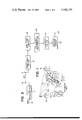
FIG. 4 shows waveforms of signals at various stages in the block diagram shown in FIG. 3;
FIG. 5 shows the average error rate performance;
FIG. 6 is a block diagram of a prior multicarrier diversity system;
FIG. 7 shows the spectrum of the frequency modulated signals of the diversity system shown in FIG. 6;
FIG. 8 is the spectrum of the output of a frequency discriminator of the receiver shown in FIG. 6;
FIG. 9 is the spectrum of the frequency modulated signals of the present invention; and
FIGS. 10 and 11 are block diagrams of first and second embodiments, respectively, of the present invention.
Prior to the description of the present invention, the influence of fading on digital signal transmission in land mobile radio will be described. Referring to FIG. 1, in land mobile radio there exist many buildings between a base station 10 and a mobile station 11 so that digital transmission between base station and mobile station usually employs not only by a direct line-of-sight route but also multiple random paths 131, 132, . . . because of reflection. Thus, in case of UHF land mobile radio, rapid and deep multipath fading phenomenon (variation in magnitude of the received signal envelope) occurs on the received signal as the mobile station 11 moves as indicated in FIG. 2. As shown in FIG. 3, according to known techniques a digital signal is applied to an input terminal 14 of an FM transmitter 15 of the base station 10, and a frequency modulated (FM) signal is generated and transmitted from an antenna 16. The received signal from an antenna 17 of the mobile station 11 is passed through a bandpass filter 18, a limiter 19, a frequency discriminator 20, a low pass filter 21 and a decision circuit 22 so that a regenerated digital signal is derived from an output terminal 23. However, because of the fading, it occurs very frequently that the regenerated digital signal is in error, i.e. different from the transmitted digital signal. This will be described with particular reference to FIG. 4 showing the waveforms at the various stages shown in FIG. 3.
The baseband digital signal em (t) consisting of "1"s and "0"s is shown in FIG. 4(a). The output v(t) from the FM transmitter 15 as shown in FIG. 4(b) is transmitted from the antenna 16. As described above with reference to FIG. 1, the rapid and deep fading occurs on the received signal w(t). Due to fading, the received signal w(t) very frequently drops under the noise level as shown at portion A in FIG. 4(c), and the noise dominates. As a result, the output x(t) of the limiter 19 contains the amplified noise at the portion A of the received signal as indicated in FIG. 4(d), and at the output y(t) of the frequency discriminator 20, the noise dominates as indicated at (e) in FIG. 4. The output of the low-pass filter 21 is applied to the decision circuit 22 which decides whether the output is "1" or "0". The regenerated signal em '(t) is often different from the transmitted digital signal em (t) as shown at (g) in FIG. 4.
As a result, even if the base station 10 has transmitted the digital signal "1", the regenerated signal is not always "1". Thus the digital transmission performance is greatly degraded. When the received signal envelope drops under the noise level, the noise dominates as shown in FIG. 4(f) so that the low-pass filter output fluctuates randomly as indicated by the solid lines A and the broken lines B in FIG. 4(f) at or near the time t4 when the decision of "0" or "1" must be made. As a consequence, the regenerated signal becomes "1" at one time and "0" at another time. That is, when the low-pass filter output level happens to be above the thereshold level as indicated by the solid line A in FIG. 4(f) at the time t4, it is decided as "1", and the regenerated signal pattern (. . . 1, 0, 1, 1, 0, 1, . . .) coincides with the transmitted signal pattern (. . . 1, 0, 1, 1, 0, 1, . . .). However, when the low-pass filter output level is below the level as indicated by the broken lines B at (f) in FIG. 4 at the time t4, it is decided as "0" so that the regenerated signal pattern (. . . 1, 0, 1, 0, 0, 1, . . .) does not coincide with the transmitted signal pattern. As described above, when the envelope of the received signal is small, an error occurs due to the noise.
FIG. 5 shows average error rate performance, the average error rate being plotted as a function of the mean C/N (received carrier power to noise power) ratio. The curve A is for the case of no fading, whereas the curve B is for the case of Rayleigh fading. It is seen that in order to maintain the average error rate same the same as the average error rate for the case of no fading, a considerably greater transmitter power is required in land mobile radio.
To reduce the influence of fading, many diversity techniques have been proposed. One of the most useful techniques is multicarrier diversity. As shown in FIG. 6, the baseband digital signal applied to the input terminal 14 is delivered to a plurality of FM transmitters 241, 242, . . . , and 24n to generate a plurality of FM signals the carrier frequencies of which are separated from each other by at least twice the baseband filter bandwidth. The signals are transmitted from separate a antennas 251, 252, . . . , and 25n. It is assumed that the carrier frequencies of the FM transmitters 241, 242, . . . , and 24n are fc1, fc2, . . . , and fcn, respectively and the corresponding spectrum of the FM signals is shown in FIG. 7. That is, the FM signals v1 (t), v2 (t), . . . , and vn (t) transmitted from the antennas 251, 252, . . . , and 25n connected to their respective FM transmitters 241, 242, . . , and 24n are deviated from the carrier frequencies fc1, fc2, . . . , and fcn by +Δ fd when "1" is transmitted and by -Δ fd when "0" is transmitted.
The FM signals are received by the antenna 17 of the receiver of the type shown in FIG. 3, the band-pass filter 18 having a sufficient bandwidth to pass all of w1 (t), w2 (t), . . . , and wn (t). As such a large number of waves are received simultaneously, the interference therebetween results in intermodulation beats in the output of the frequency discriminator 20 so that means must be provided to prevent the influence of the beats. FIG. 8 shows the spectrum of the output of the frequency discriminator 20 when two carrier frequencies fc1 and fc2 are used. It is assumed that the baseband digital signals have no DC component and have frequency components up to W Hz and that the low-pass filter 21 has a bandwidth of W Hz. The harmonic components S1, S2, S3, . . . due to beats appear and are centered around the frequencies which are the multiples of the difference frequency δf0 (= |fc1 - fc2 |) between the two frequencies fc1 and fc2. In order the prevent these harmonic components from falling into the bandwidth of the low-pass filter 20, the difference frequency δf0 must be at least twice the baseband filter bandwidth W Hz.
Assume that the envelopes of the received FM signals w1 (t) and w2 (t) be A1 and A2. If the difference frequency δf0 is larger than 2W Hz, it is considered that only the FM signal w1 (t) is received when A1 > A2 and on the other hand when A2 > A1 only the FM signal w2 (t) is received. As a result, even if the envelope A1 of the FM signal w1 (t) becomes small due to fading, the error does not occur on the regenerated signal envelopes when the amplitude A2 of the other FM signal w2 (t) is sufficiently large. However, when both envelopes of the FM signals w1 (t) and w2 (t) are lower than the noise level, error occurs on the regenerated signal, but this probability is much smaller than the probability thereof when only one FM signal is received, so that the influence of fading may be reduced.
Based upon the above described principle, a plurality of frequency modulators generate the FM signals separated by twice the baseband filter bandwidth W Hz, and the frequency modulated signals are transmitted from a plurality of antennas spaced apart from each other by a suitable distance. Thus the influence of fading may be substantially reduced. However, in case of a baseband digital signal of low-bit-rate and high carrier frequency in the UHF range, the ratio of the difference between adjacent carrier frequencies to the carrier frequency becomes very small, and then it becomes very difficult to separate carrier frequencies from each other by at least twice the baseband filter bandwidth.
The principle of the present invention is that contrary to the prior system utilizing different carrier frequencies, different peak deviations are utilized so that the spectrum of a plurality of transmitted FM signals may be generated as shown in FIG. 9. More particularly a plurality of FM signals of a common carrier frequency f0 are transmitted and received by a receiver of the type described in FIG. 6, the band-pass filter 18 having a bandwidth sufficient to pass all of the FM signals. Because of the interference or intermodulation between the signals, the output of the frequency discriminator contains beats so that, as described above, means must be provided to prevent the influence of the beats. When two signals are transmitted the spectrum of the output of the frequency discriminator 20 is just the same as that shown in FIG. 8 except that δf0 = |Δfd1 - Δfd2 |. When δf0 ≧ 2W, the harmonic components S1, S2, S3, . . . due to beats will not fall into the bandwidth of the low-pass filter 21 as described hereinbefore. Thus the effect of the present invention is similar to those attained by the prior diversity system utilizing a plurality of different carrier frequencies. That is, the influence of fading may be substantially reduced. Furthermore the present invention employing FM signals with the same carrier frequency and different peak frequency deviations may be more easily practiced than the prior art diversity systems utilizing different carrier frequencies.
Next referring to FIG. 10, the first embodiment of the present invention will be described in detail. The baseband digital signal applied to an input terminal 26 is delivered to a plurality of baseband amplifiers 271, 272, . . . , and 27n, the outputs of which are applied to frequency modulators 281, 282, . . . , and 28n each consisting of an integrator 29 and a phase modulator 30. The phase modulator 30 modulates the phase of the output of a frequency fs of an oscillator 31 with the output of the integrator 29. As a result, the output of the phase modulator 30 becomes the FM signal of a carrier frequency fs, and is converted by a multiplexer 32 into the FM signal of the desired carrier frequency f0. The output of the multiplexer 32 is amplified by a high frequency amplifier 33 to a desired power and transmitted from an antenna 34.
In the first embodiment with the above construction, the adjustment of the frequency deviation may be attained by adjusting the gains of the baseband amplifiers 271, 272, . . . , and 27n. That is, the different gains of the baseband amplifiers 271, 272, . . . , and 27n result in different frequency deviations of the FM signals transmitted from the antennas 341, 342, . . . , and 34n. With the multiplexers 321, 322, . . . , and 32n with a multiplex factor M, the carrier frequency f0 of the output signal is given by f0 = Mfs, where fs is the frequency of the oscillator 31.
Under these conditions the FM signals with the peak frequency deviations ±Δ fd1, ±Δ fd2, . . . , and ±Δ fdn may be easily generated.
Next referring to FIG. 11 the second embodiment of the present invention will be described in detail. In the second embodiment, the frequency modulator 28 consists of a combiner 35, a voltage-controlled oscillator (VCO) 36 whose frequency is controlled by an external voltage, a phase detector 37 and a low-pass filter 38. The baseband digital signal applied to the input terminal 26 is amplified by the baseband amplifier 27 and then applied to the combiner 35. The output of the oscillator 31 is applied to the phase detectors 371, 372, . . . , and 37n.
Next the principle of operation of the second embodiment with the above construction will be described. First the fundamental principle will be explained. If there is no signal at the input terminal 25 the result would be a phase locked loop, which is well known and is explained in detail in "Phase-lock Techniques", F. M. Gardner, John-Wiley Sons, Inc., New York, 1967. In the phase-locked loop, the outputs of the VCO 36 and the output of the reference oscillator 31 are applied to the phase detector 37 so that their phase difference may be detected and the output representative of the difference in phase may be derived. Only the DC component of the output of the phase detector 37 is passed through the corresponding low pass filter 38 and is applied to the corresponding VCO 36 as a control voltage. When the frequency of the VCO 36 is lower than the reference frequency, the output voltage of the low pass filter 38 raises, increasing the frequency of the VCO 36. On the other hand, when the frequency of the VCO 36 is higher than the reference frequency, the output voltage of the low pass filter 38 drops, decreasing the frequency of the VCO 36. As a result, the VCO 36 is always pulled into the phase locked state with the reference frequency oscillator 31 in such a manner that the frequency of the VCO 36 is exactly equal to that of the reference frequency oscillator 31. Thus the frequencies of all of the VCOs 361, 362, . . . , and 36n are equal to the frequency fs of the reference frequency oscillator 31.
Next the principle of operation will be described. The baseband digital signal which has been amplified by the baseband amplifiers 27 and the outputs of the low pass filters 38 are applied to the corresponding combiners 35, and their sum is applied as a control voltage to the corresponding VCOs 36. That is, the output voltage of the low pass filter 38 controls the carrier frequency, whereas the output of the baseband amplifier 27 controls the frequency deviation of the FM signal. As described above, the frequency of the VCO 36 is in proportion to the control voltage so that the VCO generates FM signal of which carrier frequency is equal to that of the reference frequency oscillator 31.
This FM signal is applied to the corresponding phase detector 37 and is compared in phase with the output of the reference frequency oscillator 31, and the phase detector output having the frequency components similar to those of the baseband digital signal is derived. However, the low pass filter 38 does not pass the components generated as a result of the frequency modulation with the baseband digital signal, and only pass the DC component. The DC component controls the carrier frequency, and is exactly equal to the output of a low-pass filter without signal at the input terminal 26. As described above, the feedback loop, the VCO 36 → the phase detector 37 → the low-pass filter 38 → the VCO 36 is established so that the carrier frequency may be always equal to the frequency of the oscillator 31.
With the frequency modulators 281, 282, . . . , and 28n each utilizing a phaselock technique, the carrier frequencies are exactly equal to the frequency of the oscillator 31, and the output of the oscillator 31 is applied to each of the frequency modulators 281, 282, . . . , and 28n so that the carrier frequencies of the FM signals generated by each frequency modulators are same. The adjustment of the peak frequency deviations may be accomplished by adjusting the gains of the baseband amplifiers 271, 272, . . . , and 27n as described above.
Claims (8)
1. A diversity system comprising
(a) a reference frequency oscillator,
(b) a plurality of frequency modulators each having means which generates frequency modulated signals the carrier frequencies of which are equal to each other and to that of said reference frequency oscillator,
(c) said plurality of frequency modulators generating frequency modulated signals with a common baseband digital signal being applied to said plurality of frequency modulators in such a manner that the peak frequency deviations of said modulated signals are different from each other, and
(d) the frequency modulated signals being transmitted from respective antennas connected to said plurality of frequency modulators, respectively.
2. A diversity system as set forth in claim 1 wherein each of said plurality of frequency modulators consists of an integrator and a phase modulator.
3. A diversity system as set forth in claim 1 wherein each of said plurality of frequency modulators consists of a combiner and a phase locked loop.
4. A diversity system as set forth in claim 3 wherein said phase locked loop consists of a voltage-controlled oscillator, a phase detector, and low pass filter.
5. A diversity system as set forth in claim 1, further comprising a receiver including a predetection filter having a bandwidth capable of receiving all of the modulated carriers transmitted from said transmitters.
6. A diversity system as set forth in claim 2, further comprising a receiver including a predetection filter having a bandwidth capable of receiving all of the modulated carriers transmitted from said transmitters.
7. A diversity system comprising:
(a) at least two angularly modulating transmitters;
(b) carriers in each transmitter being angularly modulated by a common baseband digital signal to different peak frequency deviations of said modulated carriers from each other; and
(c) said modulated carriers being transmitted from respective antennas connected to each transmitter.
8. A diversity system comprising:
(a) at least two angularly modulating transmitters;
(b) carriers of identical frequency in each transmitter being angularly modulated by a common baseband digital signal to different peak frequency deviations of said modulated carriers from each other; and
(c) said modulated carriers being transmitted from respective antennas connected to each transmitter.
Applications Claiming Priority (2)
| Application Number | Priority Date | Filing Date | Title |
|---|---|---|---|
| JP5767876A JPS52141113A (en) | 1976-05-19 | 1976-05-19 | Transmission diversity system |
| JP51-57678 | 1976-05-19 |
Publications (1)
| Publication Number | Publication Date |
|---|---|
| US4142155A true US4142155A (en) | 1979-02-27 |
Family
ID=13062576
Family Applications (1)
| Application Number | Title | Priority Date | Filing Date |
|---|---|---|---|
| US05/795,870 Expired - Lifetime US4142155A (en) | 1976-05-19 | 1977-05-11 | Diversity system |
Country Status (7)
| Country | Link |
|---|---|
| US (1) | US4142155A (en) |
| JP (1) | JPS52141113A (en) |
| CA (1) | CA1088630A (en) |
| DE (1) | DE2722570C3 (en) |
| FR (1) | FR2352451A1 (en) |
| GB (1) | GB1580744A (en) |
| SE (1) | SE428623B (en) |
Cited By (47)
| Publication number | Priority date | Publication date | Assignee | Title |
|---|---|---|---|---|
| US4363132A (en) * | 1980-01-29 | 1982-12-07 | Thomson-Csf | Diversity radio transmission system having a simple and economical structure |
| US4385381A (en) * | 1979-08-29 | 1983-05-24 | U.S. Philips Corporation | Digital radio transmission system for transmitting a plurality of information signals by a network of transmitters having substantially the same carrier frequencies |
| US4397036A (en) * | 1978-05-10 | 1983-08-02 | Nippon Telegraph And Telephone Public Corporation | Diversity system |
| US5285478A (en) * | 1991-10-31 | 1994-02-08 | Massachusetts Institute Of Technology | Communication system utilizing self-similar signals |
| US6049706A (en) * | 1998-10-21 | 2000-04-11 | Parkervision, Inc. | Integrated frequency translation and selectivity |
| US6061555A (en) * | 1998-10-21 | 2000-05-09 | Parkervision, Inc. | Method and system for ensuring reception of a communications signal |
| US6061551A (en) * | 1998-10-21 | 2000-05-09 | Parkervision, Inc. | Method and system for down-converting electromagnetic signals |
| US6091940A (en) * | 1998-10-21 | 2000-07-18 | Parkervision, Inc. | Method and system for frequency up-conversion |
| US20010038318A1 (en) * | 1999-11-24 | 2001-11-08 | Parker Vision, Inc. | Phased array antenna applications for universal frequency translation |
| US6370371B1 (en) | 1998-10-21 | 2002-04-09 | Parkervision, Inc. | Applications of universal frequency translation |
| US20020042257A1 (en) * | 2000-04-14 | 2002-04-11 | Sorrells David F. | Apparatus, system, and method for down-converting and up-converting electromagnetic signals |
| US20020049038A1 (en) * | 2000-01-28 | 2002-04-25 | Sorrells David F. | Wireless and wired cable modem applications of universal frequency translation technology |
| US20020124036A1 (en) * | 2000-11-14 | 2002-09-05 | Parkervision, Inc. | Method and apparatus for a parallel correlator and applications thereof |
| US20030022640A1 (en) * | 1999-08-23 | 2003-01-30 | Parker Vision, Inc. | Method and system for frequency up-conversion |
| US6542722B1 (en) | 1998-10-21 | 2003-04-01 | Parkervision, Inc. | Method and system for frequency up-conversion with variety of transmitter configurations |
| US6560301B1 (en) | 1998-10-21 | 2003-05-06 | Parkervision, Inc. | Integrated frequency translation and selectivity with a variety of filter embodiments |
| US20030128776A1 (en) * | 2001-11-09 | 2003-07-10 | Parkervision, Inc | Method and apparatus for reducing DC off sets in a communication system |
| US20030181189A1 (en) * | 1999-04-16 | 2003-09-25 | Sorrells David F. | Method and apparatus for reducing DC offsets in communication systems using universal frequency translation technology |
| US20040013177A1 (en) * | 2002-07-18 | 2004-01-22 | Parker Vision, Inc. | Networking methods and systems |
| US20040015420A1 (en) * | 2002-07-18 | 2004-01-22 | Sorrells David F. | Networking methods and systems |
| US6694128B1 (en) | 1998-08-18 | 2004-02-17 | Parkervision, Inc. | Frequency synthesizer using universal frequency translation technology |
| US6704558B1 (en) | 1999-01-22 | 2004-03-09 | Parkervision, Inc. | Image-reject down-converter and embodiments thereof, such as the family radio service |
| US6704549B1 (en) | 1999-03-03 | 2004-03-09 | Parkvision, Inc. | Multi-mode, multi-band communication system |
| US20040185901A1 (en) * | 2003-03-18 | 2004-09-23 | Tdk Corporation | Electronic device for wireless communications and reflector device for wireless communication cards |
| US6813485B2 (en) | 1998-10-21 | 2004-11-02 | Parkervision, Inc. | Method and system for down-converting and up-converting an electromagnetic signal, and transforms for same |
| US20040230628A1 (en) * | 2000-11-14 | 2004-11-18 | Rawlins Gregory S. | Methods, systems, and computer program products for parallel correlation and applications thereof |
| US6873836B1 (en) | 1999-03-03 | 2005-03-29 | Parkervision, Inc. | Universal platform module and methods and apparatuses relating thereto enabled by universal frequency translation technology |
| US20050100115A1 (en) * | 1999-04-16 | 2005-05-12 | Sorrells David F. | Method, system, and apparatus for balanced frequency Up-conversion of a baseband signal |
| US20050123025A1 (en) * | 1999-08-04 | 2005-06-09 | Sorrells David F. | Wireless local area network (WLAN) using universal frequency translation technology including multi-phase embodiments and circuit implementations |
| US20050136861A1 (en) * | 1998-10-21 | 2005-06-23 | Parkervision, Inc. | Method and system for frequency up-conversion with modulation embodiments |
| US6963734B2 (en) | 1999-12-22 | 2005-11-08 | Parkervision, Inc. | Differential frequency down-conversion using techniques of universal frequency translation technology |
| US6975848B2 (en) | 2002-06-04 | 2005-12-13 | Parkervision, Inc. | Method and apparatus for DC offset removal in a radio frequency communication channel |
| US7006805B1 (en) | 1999-01-22 | 2006-02-28 | Parker Vision, Inc. | Aliasing communication system with multi-mode and multi-band functionality and embodiments thereof, such as the family radio service |
| US7027786B1 (en) | 1998-10-21 | 2006-04-11 | Parkervision, Inc. | Carrier and clock recovery using universal frequency translation |
| US7054296B1 (en) | 1999-08-04 | 2006-05-30 | Parkervision, Inc. | Wireless local area network (WLAN) technology and applications including techniques of universal frequency translation |
| US7072390B1 (en) | 1999-08-04 | 2006-07-04 | Parkervision, Inc. | Wireless local area network (WLAN) using universal frequency translation technology including multi-phase embodiments |
| US7085335B2 (en) | 2001-11-09 | 2006-08-01 | Parkervision, Inc. | Method and apparatus for reducing DC offsets in a communication system |
| US7110435B1 (en) | 1999-03-15 | 2006-09-19 | Parkervision, Inc. | Spread spectrum applications of universal frequency translation |
| EP1720265A1 (en) | 2005-05-04 | 2006-11-08 | Siemens Aktiengesellschaft | Diversity system with only one receive antenna |
| US20070033888A1 (en) * | 2003-05-09 | 2007-02-15 | HENDRICKS Robert | Cap-on-cap mounting block |
| US20070230611A1 (en) * | 1999-04-16 | 2007-10-04 | Parkervision, Inc. | Apparatus and method of differential IQ frequency up-conversion |
| US7295826B1 (en) | 1998-10-21 | 2007-11-13 | Parkervision, Inc. | Integrated frequency translation and selectivity with gain control functionality, and applications thereof |
| US7321640B2 (en) | 2002-06-07 | 2008-01-22 | Parkervision, Inc. | Active polyphase inverter filter for quadrature signal generation |
| US7515896B1 (en) | 1998-10-21 | 2009-04-07 | Parkervision, Inc. | Method and system for down-converting an electromagnetic signal, and transforms for same, and aperture relationships |
| US7554508B2 (en) | 2000-06-09 | 2009-06-30 | Parker Vision, Inc. | Phased array antenna applications on universal frequency translation |
| US7724845B2 (en) | 1999-04-16 | 2010-05-25 | Parkervision, Inc. | Method and system for down-converting and electromagnetic signal, and transforms for same |
| US8295406B1 (en) | 1999-08-04 | 2012-10-23 | Parkervision, Inc. | Universal platform module for a plurality of communication protocols |
Citations (3)
| Publication number | Priority date | Publication date | Assignee | Title |
|---|---|---|---|---|
| US2429504A (en) * | 1943-11-09 | 1947-10-21 | Hartford Nat Bank & Trust Co | Frequency modulation network |
| US3713040A (en) * | 1971-12-23 | 1973-01-23 | Hewlett Packard Co | Signal frequency controller |
| US4051438A (en) * | 1975-09-11 | 1977-09-27 | International Telephone And Telegraph Corporation | Co-channel multiple signal broadcasting system |
Family Cites Families (1)
| Publication number | Priority date | Publication date | Assignee | Title |
|---|---|---|---|---|
| US3348150A (en) * | 1964-07-27 | 1967-10-17 | Bell Telephone Labor Inc | Diversity transmission system |
-
1976
- 1976-05-19 JP JP5767876A patent/JPS52141113A/en active Pending
-
1977
- 1977-05-11 GB GB19738/77A patent/GB1580744A/en not_active Expired
- 1977-05-11 US US05/795,870 patent/US4142155A/en not_active Expired - Lifetime
- 1977-05-17 FR FR7715077A patent/FR2352451A1/en active Granted
- 1977-05-17 SE SE7705875A patent/SE428623B/en not_active IP Right Cessation
- 1977-05-18 DE DE2722570A patent/DE2722570C3/en not_active Expired
- 1977-05-18 CA CA278,726A patent/CA1088630A/en not_active Expired
Patent Citations (3)
| Publication number | Priority date | Publication date | Assignee | Title |
|---|---|---|---|---|
| US2429504A (en) * | 1943-11-09 | 1947-10-21 | Hartford Nat Bank & Trust Co | Frequency modulation network |
| US3713040A (en) * | 1971-12-23 | 1973-01-23 | Hewlett Packard Co | Signal frequency controller |
| US4051438A (en) * | 1975-09-11 | 1977-09-27 | International Telephone And Telegraph Corporation | Co-channel multiple signal broadcasting system |
Non-Patent Citations (2)
| Title |
|---|
| "Modulation Theory," Harold S. Black, 1953, pp. 192-195, D. Van Nostrand Co. Inc. |
| "Modulation Theory," Harold S. Black, 1953, pp. 192-195, D. Van Nostrand Co. Inc. * |
Cited By (150)
| Publication number | Priority date | Publication date | Assignee | Title |
|---|---|---|---|---|
| US4397036A (en) * | 1978-05-10 | 1983-08-02 | Nippon Telegraph And Telephone Public Corporation | Diversity system |
| US4385381A (en) * | 1979-08-29 | 1983-05-24 | U.S. Philips Corporation | Digital radio transmission system for transmitting a plurality of information signals by a network of transmitters having substantially the same carrier frequencies |
| US4363132A (en) * | 1980-01-29 | 1982-12-07 | Thomson-Csf | Diversity radio transmission system having a simple and economical structure |
| US5285478A (en) * | 1991-10-31 | 1994-02-08 | Massachusetts Institute Of Technology | Communication system utilizing self-similar signals |
| US6694128B1 (en) | 1998-08-18 | 2004-02-17 | Parkervision, Inc. | Frequency synthesizer using universal frequency translation technology |
| US6798351B1 (en) | 1998-10-21 | 2004-09-28 | Parkervision, Inc. | Automated meter reader applications of universal frequency translation |
| US6542722B1 (en) | 1998-10-21 | 2003-04-01 | Parkervision, Inc. | Method and system for frequency up-conversion with variety of transmitter configurations |
| US6091940A (en) * | 1998-10-21 | 2000-07-18 | Parkervision, Inc. | Method and system for frequency up-conversion |
| US6266518B1 (en) | 1998-10-21 | 2001-07-24 | Parkervision, Inc. | Method and system for down-converting electromagnetic signals by sampling and integrating over apertures |
| US8340618B2 (en) | 1998-10-21 | 2012-12-25 | Parkervision, Inc. | Method and system for down-converting an electromagnetic signal, and transforms for same, and aperture relationships |
| US7826817B2 (en) | 1998-10-21 | 2010-11-02 | Parker Vision, Inc. | Applications of universal frequency translation |
| US6370371B1 (en) | 1998-10-21 | 2002-04-09 | Parkervision, Inc. | Applications of universal frequency translation |
| US8233855B2 (en) | 1998-10-21 | 2012-07-31 | Parkervision, Inc. | Up-conversion based on gated information signal |
| US8190116B2 (en) | 1998-10-21 | 2012-05-29 | Parker Vision, Inc. | Methods and systems for down-converting a signal using a complementary transistor structure |
| US6421534B1 (en) | 1998-10-21 | 2002-07-16 | Parkervision, Inc. | Integrated frequency translation and selectivity |
| US8190108B2 (en) | 1998-10-21 | 2012-05-29 | Parkervision, Inc. | Method and system for frequency up-conversion |
| US20020160809A1 (en) * | 1998-10-21 | 2002-10-31 | Parker Vision, Inc. | Applications of universal frequency translation |
| US8160534B2 (en) | 1998-10-21 | 2012-04-17 | Parkervision, Inc. | Applications of universal frequency translation |
| US6836650B2 (en) | 1998-10-21 | 2004-12-28 | Parkervision, Inc. | Methods and systems for down-converting electromagnetic signals, and applications thereof |
| US20030068990A1 (en) * | 1998-10-21 | 2003-04-10 | Parkervision, Inc. | Method and system for frequency up-conversion with a variety of transmitter configurations |
| US6560301B1 (en) | 1998-10-21 | 2003-05-06 | Parkervision, Inc. | Integrated frequency translation and selectivity with a variety of filter embodiments |
| US6580902B1 (en) | 1998-10-21 | 2003-06-17 | Parkervision, Inc. | Frequency translation using optimized switch structures |
| US20030112895A1 (en) * | 1998-10-21 | 2003-06-19 | Parkervision, Inc. | Intergrated frequency translation and selectivity |
| US8019291B2 (en) | 1998-10-21 | 2011-09-13 | Parkervision, Inc. | Method and system for frequency down-conversion and frequency up-conversion |
| US20110183640A1 (en) * | 1998-10-21 | 2011-07-28 | Parkervision, Inc. | Method and System for Down-Converting an Electromagnetic Signal, and Transforms for Same, and Aperture Relationships |
| US20030186670A1 (en) * | 1998-10-21 | 2003-10-02 | Sorrells David F. | Method and circuit or down-converting a signal |
| US6647250B1 (en) | 1998-10-21 | 2003-11-11 | Parkervision, Inc. | Method and system for ensuring reception of a communications signal |
| US20110151821A1 (en) * | 1998-10-21 | 2011-06-23 | Parkervision, Inc. | Methods and Systems for Down-Converting a Signal Using a Complementary Transistor Structure |
| US7937059B2 (en) | 1998-10-21 | 2011-05-03 | Parkervision, Inc. | Converting an electromagnetic signal via sub-sampling |
| US7936022B2 (en) | 1998-10-21 | 2011-05-03 | Parkervision, Inc. | Method and circuit for down-converting a signal |
| US7245886B2 (en) | 1998-10-21 | 2007-07-17 | Parkervision, Inc. | Method and system for frequency up-conversion with modulation embodiments |
| US6061555A (en) * | 1998-10-21 | 2000-05-09 | Parkervision, Inc. | Method and system for ensuring reception of a communications signal |
| US20070259627A1 (en) * | 1998-10-21 | 2007-11-08 | Parkervision, Inc. | Method and system for frequency up-conversion with modulation embodiments |
| US7295826B1 (en) | 1998-10-21 | 2007-11-13 | Parkervision, Inc. | Integrated frequency translation and selectivity with gain control functionality, and applications thereof |
| US7865177B2 (en) | 1998-10-21 | 2011-01-04 | Parkervision, Inc. | Method and system for down-converting an electromagnetic signal, and transforms for same, and aperture relationships |
| US7218907B2 (en) | 1998-10-21 | 2007-05-15 | Parkervision, Inc. | Method and circuit for down-converting a signal |
| US6813485B2 (en) | 1998-10-21 | 2004-11-02 | Parkervision, Inc. | Method and system for down-converting and up-converting an electromagnetic signal, and transforms for same |
| US6353735B1 (en) | 1998-10-21 | 2002-03-05 | Parkervision, Inc. | MDG method for output signal generation |
| US6061551A (en) * | 1998-10-21 | 2000-05-09 | Parkervision, Inc. | Method and system for down-converting electromagnetic signals |
| US6687493B1 (en) | 1998-10-21 | 2004-02-03 | Parkervision, Inc. | Method and circuit for down-converting a signal using a complementary FET structure for improved dynamic range |
| US7697916B2 (en) | 1998-10-21 | 2010-04-13 | Parkervision, Inc. | Applications of universal frequency translation |
| US7693502B2 (en) | 1998-10-21 | 2010-04-06 | Parkervision, Inc. | Method and system for down-converting an electromagnetic signal, transforms for same, and aperture relationships |
| US6049706A (en) * | 1998-10-21 | 2000-04-11 | Parkervision, Inc. | Integrated frequency translation and selectivity |
| US20100056084A1 (en) * | 1998-10-21 | 2010-03-04 | Parkervision, Inc. | Frequency Conversion Based on Gated Information Signal |
| US7620378B2 (en) | 1998-10-21 | 2009-11-17 | Parkervision, Inc. | Method and system for frequency up-conversion with modulation embodiments |
| US20050136861A1 (en) * | 1998-10-21 | 2005-06-23 | Parkervision, Inc. | Method and system for frequency up-conversion with modulation embodiments |
| US7076011B2 (en) | 1998-10-21 | 2006-07-11 | Parkervision, Inc. | Integrated frequency translation and selectivity |
| US7308242B2 (en) | 1998-10-21 | 2007-12-11 | Parkervision, Inc. | Method and system for down-converting and up-converting an electromagnetic signal, and transforms for same |
| US20050202797A1 (en) * | 1998-10-21 | 2005-09-15 | Sorrells David F. | Methods and systems for down-converting electromagnetic signals, and applications thereof |
| US20050215207A1 (en) * | 1998-10-21 | 2005-09-29 | Parkervision, Inc. | Method and system for frequency up-conversion with a variety of transmitter configurations |
| US20090221257A1 (en) * | 1998-10-21 | 2009-09-03 | Parkervision, Inc. | Method and System For Down-Converting An Electromagnetic Signal, And Transforms For Same, And Aperture Relationships |
| US20090181627A1 (en) * | 1998-10-21 | 2009-07-16 | Parkervision, Inc. | Applications of Universal Frequency Translation |
| US20050272395A1 (en) * | 1998-10-21 | 2005-12-08 | Parkervision, Inc. | Method and circuit for down-converting a signal |
| US7529522B2 (en) | 1998-10-21 | 2009-05-05 | Parkervision, Inc. | Apparatus and method for communicating an input signal in polar representation |
| US7321735B1 (en) | 1998-10-21 | 2008-01-22 | Parkervision, Inc. | Optical down-converter using universal frequency translation technology |
| US7515896B1 (en) | 1998-10-21 | 2009-04-07 | Parkervision, Inc. | Method and system for down-converting an electromagnetic signal, and transforms for same, and aperture relationships |
| US7376410B2 (en) | 1998-10-21 | 2008-05-20 | Parkervision, Inc. | Methods and systems for down-converting a signal using a complementary transistor structure |
| US7016663B2 (en) | 1998-10-21 | 2006-03-21 | Parkervision, Inc. | Applications of universal frequency translation |
| US7027786B1 (en) | 1998-10-21 | 2006-04-11 | Parkervision, Inc. | Carrier and clock recovery using universal frequency translation |
| US7389100B2 (en) | 1998-10-21 | 2008-06-17 | Parkervision, Inc. | Method and circuit for down-converting a signal |
| US7039372B1 (en) | 1998-10-21 | 2006-05-02 | Parkervision, Inc. | Method and system for frequency up-conversion with modulation embodiments |
| US7050508B2 (en) | 1998-10-21 | 2006-05-23 | Parkervision, Inc. | Method and system for frequency up-conversion with a variety of transmitter configurations |
| US7006805B1 (en) | 1999-01-22 | 2006-02-28 | Parker Vision, Inc. | Aliasing communication system with multi-mode and multi-band functionality and embodiments thereof, such as the family radio service |
| US6704558B1 (en) | 1999-01-22 | 2004-03-09 | Parkervision, Inc. | Image-reject down-converter and embodiments thereof, such as the family radio service |
| US7483686B2 (en) | 1999-03-03 | 2009-01-27 | Parkervision, Inc. | Universal platform module and methods and apparatuses relating thereto enabled by universal frequency translation technology |
| US20050164670A1 (en) * | 1999-03-03 | 2005-07-28 | Parkervision, Inc. | Universal platform module and methods and apparatuses relating thereto enabled by universal frequency translation technology |
| US6704549B1 (en) | 1999-03-03 | 2004-03-09 | Parkvision, Inc. | Multi-mode, multi-band communication system |
| US6873836B1 (en) | 1999-03-03 | 2005-03-29 | Parkervision, Inc. | Universal platform module and methods and apparatuses relating thereto enabled by universal frequency translation technology |
| US7599421B2 (en) | 1999-03-15 | 2009-10-06 | Parkervision, Inc. | Spread spectrum applications of universal frequency translation |
| US7110435B1 (en) | 1999-03-15 | 2006-09-19 | Parkervision, Inc. | Spread spectrum applications of universal frequency translation |
| US7693230B2 (en) | 1999-04-16 | 2010-04-06 | Parkervision, Inc. | Apparatus and method of differential IQ frequency up-conversion |
| US8224281B2 (en) | 1999-04-16 | 2012-07-17 | Parkervision, Inc. | Down-conversion of an electromagnetic signal with feedback control |
| US8594228B2 (en) | 1999-04-16 | 2013-11-26 | Parkervision, Inc. | Apparatus and method of differential IQ frequency up-conversion |
| US7190941B2 (en) | 1999-04-16 | 2007-03-13 | Parkervision, Inc. | Method and apparatus for reducing DC offsets in communication systems using universal frequency translation technology |
| US7894789B2 (en) | 1999-04-16 | 2011-02-22 | Parkervision, Inc. | Down-conversion of an electromagnetic signal with feedback control |
| US20100260289A1 (en) * | 1999-04-16 | 2010-10-14 | Parkervision, Inc. | Method, System, and Apparatus for Balanced Frequency Up-Conversion of a Baseband Signal |
| US8036304B2 (en) | 1999-04-16 | 2011-10-11 | Parkervision, Inc. | Apparatus and method of differential IQ frequency up-conversion |
| US7224749B2 (en) | 1999-04-16 | 2007-05-29 | Parkervision, Inc. | Method and apparatus for reducing re-radiation using techniques of universal frequency translation technology |
| US8077797B2 (en) | 1999-04-16 | 2011-12-13 | Parkervision, Inc. | Method, system, and apparatus for balanced frequency up-conversion of a baseband signal |
| US7773688B2 (en) | 1999-04-16 | 2010-08-10 | Parkervision, Inc. | Method, system, and apparatus for balanced frequency up-conversion, including circuitry to directly couple the outputs of multiple transistors |
| US7724845B2 (en) | 1999-04-16 | 2010-05-25 | Parkervision, Inc. | Method and system for down-converting and electromagnetic signal, and transforms for same |
| US7272164B2 (en) | 1999-04-16 | 2007-09-18 | Parkervision, Inc. | Reducing DC offsets using spectral spreading |
| US20100303178A1 (en) * | 1999-04-16 | 2010-12-02 | Parkervision, Inc. | Method and System for Down-Converting an Electromagnetic Signal, and Transforms for Same |
| US20070230611A1 (en) * | 1999-04-16 | 2007-10-04 | Parkervision, Inc. | Apparatus and method of differential IQ frequency up-conversion |
| US20100111150A1 (en) * | 1999-04-16 | 2010-05-06 | Parkervision, Inc. | Wireless Local Area Network (WLAN) Using Universal Frequency Translation Technology Including Multi-Phase Embodiments |
| US6879817B1 (en) | 1999-04-16 | 2005-04-12 | Parkervision, Inc. | DC offset, re-radiation, and I/Q solutions using universal frequency translation technology |
| US7929638B2 (en) | 1999-04-16 | 2011-04-19 | Parkervision, Inc. | Wireless local area network (WLAN) using universal frequency translation technology including multi-phase embodiments |
| US20050100115A1 (en) * | 1999-04-16 | 2005-05-12 | Sorrells David F. | Method, system, and apparatus for balanced frequency Up-conversion of a baseband signal |
| US7539474B2 (en) | 1999-04-16 | 2009-05-26 | Parkervision, Inc. | DC offset, re-radiation, and I/Q solutions using universal frequency translation technology |
| US8229023B2 (en) | 1999-04-16 | 2012-07-24 | Parkervision, Inc. | Wireless local area network (WLAN) using universal frequency translation technology including multi-phase embodiments |
| US20040002321A1 (en) * | 1999-04-16 | 2004-01-01 | Parker Vision, Inc. | Method and apparatus for reducing re-radiation using techniques of universal frequency translation technology |
| US20110092177A1 (en) * | 1999-04-16 | 2011-04-21 | Parkervision, Inc. | Down-Conversion of an Electromagnetic Signal with Feedback Control |
| US20030181189A1 (en) * | 1999-04-16 | 2003-09-25 | Sorrells David F. | Method and apparatus for reducing DC offsets in communication systems using universal frequency translation technology |
| US8223898B2 (en) | 1999-04-16 | 2012-07-17 | Parkervision, Inc. | Method and system for down-converting an electromagnetic signal, and transforms for same |
| US20060083329A1 (en) * | 1999-04-16 | 2006-04-20 | Parkervision Inc. | Methods and systems for utilizing universal frequency translators for phase and/or frequency detection |
| US20050123025A1 (en) * | 1999-08-04 | 2005-06-09 | Sorrells David F. | Wireless local area network (WLAN) using universal frequency translation technology including multi-phase embodiments and circuit implementations |
| US7054296B1 (en) | 1999-08-04 | 2006-05-30 | Parkervision, Inc. | Wireless local area network (WLAN) technology and applications including techniques of universal frequency translation |
| US7072390B1 (en) | 1999-08-04 | 2006-07-04 | Parkervision, Inc. | Wireless local area network (WLAN) using universal frequency translation technology including multi-phase embodiments |
| US8295406B1 (en) | 1999-08-04 | 2012-10-23 | Parkervision, Inc. | Universal platform module for a plurality of communication protocols |
| US7110444B1 (en) | 1999-08-04 | 2006-09-19 | Parkervision, Inc. | Wireless local area network (WLAN) using universal frequency translation technology including multi-phase embodiments and circuit implementations |
| US20070224950A1 (en) * | 1999-08-23 | 2007-09-27 | Parkervision, Inc. | Method and system for frequency up-conversion |
| US20030022640A1 (en) * | 1999-08-23 | 2003-01-30 | Parker Vision, Inc. | Method and system for frequency up-conversion |
| US7546096B2 (en) | 1999-08-23 | 2009-06-09 | Parkervision, Inc. | Frequency up-conversion using a harmonic generation and extraction module |
| US7236754B2 (en) | 1999-08-23 | 2007-06-26 | Parkervision, Inc. | Method and system for frequency up-conversion |
| US7379515B2 (en) | 1999-11-24 | 2008-05-27 | Parkervision, Inc. | Phased array antenna applications of universal frequency translation |
| US20010038318A1 (en) * | 1999-11-24 | 2001-11-08 | Parker Vision, Inc. | Phased array antenna applications for universal frequency translation |
| US7082171B1 (en) | 1999-11-24 | 2006-07-25 | Parkervision, Inc. | Phase shifting applications of universal frequency translation |
| US6963734B2 (en) | 1999-12-22 | 2005-11-08 | Parkervision, Inc. | Differential frequency down-conversion using techniques of universal frequency translation technology |
| US7292835B2 (en) | 2000-01-28 | 2007-11-06 | Parkervision, Inc. | Wireless and wired cable modem applications of universal frequency translation technology |
| US20020049038A1 (en) * | 2000-01-28 | 2002-04-25 | Sorrells David F. | Wireless and wired cable modem applications of universal frequency translation technology |
| US8295800B2 (en) | 2000-04-14 | 2012-10-23 | Parkervision, Inc. | Apparatus and method for down-converting electromagnetic signals by controlled charging and discharging of a capacitor |
| US20020042257A1 (en) * | 2000-04-14 | 2002-04-11 | Sorrells David F. | Apparatus, system, and method for down-converting and up-converting electromagnetic signals |
| US20050085208A1 (en) * | 2000-04-14 | 2005-04-21 | Parkervision, Inc. | Apparatus, system, and method for down-converting and up-converting electromagnetic signals |
| US20050085207A1 (en) * | 2000-04-14 | 2005-04-21 | Parkervision, Inc. | Apparatus, system, and method for down-converting and up-converting electromagnetic signals |
| US20050227639A1 (en) * | 2000-04-14 | 2005-10-13 | Parkervision, Inc. | Apparatus, system, and method for down converting and up converting electromagnetic signals |
| US7386292B2 (en) | 2000-04-14 | 2008-06-10 | Parkervision, Inc. | Apparatus, system, and method for down-converting and up-converting electromagnetic signals |
| US7010286B2 (en) | 2000-04-14 | 2006-03-07 | Parkervision, Inc. | Apparatus, system, and method for down-converting and up-converting electromagnetic signals |
| US7107028B2 (en) | 2000-04-14 | 2006-09-12 | Parkervision, Inc. | Apparatus, system, and method for up converting electromagnetic signals |
| US7218899B2 (en) | 2000-04-14 | 2007-05-15 | Parkervision, Inc. | Apparatus, system, and method for up-converting electromagnetic signals |
| US7822401B2 (en) | 2000-04-14 | 2010-10-26 | Parkervision, Inc. | Apparatus and method for down-converting electromagnetic signals by controlled charging and discharging of a capacitor |
| US7496342B2 (en) | 2000-04-14 | 2009-02-24 | Parkervision, Inc. | Down-converting electromagnetic signals, including controlled discharge of capacitors |
| US7554508B2 (en) | 2000-06-09 | 2009-06-30 | Parker Vision, Inc. | Phased array antenna applications on universal frequency translation |
| US20050193049A1 (en) * | 2000-11-14 | 2005-09-01 | Parkervision, Inc. | Method and apparatus for a parallel correlator and applications thereof |
| US20080294708A1 (en) * | 2000-11-14 | 2008-11-27 | Parkervision, Inc. | Methods, systems, and computer program products for parallel correlation and applications thereof |
| US20040230628A1 (en) * | 2000-11-14 | 2004-11-18 | Rawlins Gregory S. | Methods, systems, and computer program products for parallel correlation and applications thereof |
| US7454453B2 (en) | 2000-11-14 | 2008-11-18 | Parkervision, Inc. | Methods, systems, and computer program products for parallel correlation and applications thereof |
| US20020124036A1 (en) * | 2000-11-14 | 2002-09-05 | Parkervision, Inc. | Method and apparatus for a parallel correlator and applications thereof |
| US7433910B2 (en) | 2000-11-14 | 2008-10-07 | Parkervision, Inc. | Method and apparatus for the parallel correlator and applications thereof |
| US7010559B2 (en) | 2000-11-14 | 2006-03-07 | Parkervision, Inc. | Method and apparatus for a parallel correlator and applications thereof |
| US7233969B2 (en) | 2000-11-14 | 2007-06-19 | Parkervision, Inc. | Method and apparatus for a parallel correlator and applications thereof |
| US7991815B2 (en) | 2000-11-14 | 2011-08-02 | Parkervision, Inc. | Methods, systems, and computer program products for parallel correlation and applications thereof |
| US20030128776A1 (en) * | 2001-11-09 | 2003-07-10 | Parkervision, Inc | Method and apparatus for reducing DC off sets in a communication system |
| US20070086548A1 (en) * | 2001-11-09 | 2007-04-19 | Parkervision, Inc. | Method and apparatus for reducing DC offsets in a communication system |
| US7085335B2 (en) | 2001-11-09 | 2006-08-01 | Parkervision, Inc. | Method and apparatus for reducing DC offsets in a communication system |
| US8446994B2 (en) | 2001-11-09 | 2013-05-21 | Parkervision, Inc. | Gain control in a communication channel |
| US7072427B2 (en) | 2001-11-09 | 2006-07-04 | Parkervision, Inc. | Method and apparatus for reducing DC offsets in a communication system |
| US7653158B2 (en) | 2001-11-09 | 2010-01-26 | Parkervision, Inc. | Gain control in a communication channel |
| US20100086086A1 (en) * | 2001-11-09 | 2010-04-08 | Parkervision, Inc. | Gain control in a communication channel |
| US6975848B2 (en) | 2002-06-04 | 2005-12-13 | Parkervision, Inc. | Method and apparatus for DC offset removal in a radio frequency communication channel |
| US7321640B2 (en) | 2002-06-07 | 2008-01-22 | Parkervision, Inc. | Active polyphase inverter filter for quadrature signal generation |
| US7379883B2 (en) | 2002-07-18 | 2008-05-27 | Parkervision, Inc. | Networking methods and systems |
| US8160196B2 (en) | 2002-07-18 | 2012-04-17 | Parkervision, Inc. | Networking methods and systems |
| US7460584B2 (en) | 2002-07-18 | 2008-12-02 | Parkervision, Inc. | Networking methods and systems |
| US20040013177A1 (en) * | 2002-07-18 | 2004-01-22 | Parker Vision, Inc. | Networking methods and systems |
| US8407061B2 (en) | 2002-07-18 | 2013-03-26 | Parkervision, Inc. | Networking methods and systems |
| US20040015420A1 (en) * | 2002-07-18 | 2004-01-22 | Sorrells David F. | Networking methods and systems |
| US20040185901A1 (en) * | 2003-03-18 | 2004-09-23 | Tdk Corporation | Electronic device for wireless communications and reflector device for wireless communication cards |
| US8572910B2 (en) | 2003-05-09 | 2013-11-05 | Tapco International, Inc. | Cap-on-cap mounting block |
| US20070033888A1 (en) * | 2003-05-09 | 2007-02-15 | HENDRICKS Robert | Cap-on-cap mounting block |
| EP1720265A1 (en) | 2005-05-04 | 2006-11-08 | Siemens Aktiengesellschaft | Diversity system with only one receive antenna |
Also Published As
| Publication number | Publication date |
|---|---|
| SE7705875L (en) | 1977-11-20 |
| FR2352451B1 (en) | 1981-12-11 |
| GB1580744A (en) | 1980-12-03 |
| JPS52141113A (en) | 1977-11-25 |
| DE2722570A1 (en) | 1977-11-24 |
| DE2722570B2 (en) | 1981-01-15 |
| CA1088630A (en) | 1980-10-28 |
| FR2352451A1 (en) | 1977-12-16 |
| SE428623B (en) | 1983-07-11 |
| DE2722570C3 (en) | 1981-10-08 |
Similar Documents
| Publication | Publication Date | Title |
|---|---|---|
| US4142155A (en) | Diversity system | |
| CA1198169A (en) | Digital radio systems | |
| JP3173788B2 (en) | Digital transmission equipment and direct conversion receiver | |
| US4570265A (en) | Random frequency offsetting apparatus for multi-transmitter simulcast radio communications systems | |
| EP0110368B1 (en) | Burst signal transmission system | |
| US4817116A (en) | Digital radio communication system utilizing quadrature modulated carrier waves | |
| US3743941A (en) | Diversity receiver suitable for large scale integration | |
| JPH0142535B2 (en) | ||
| US6370361B1 (en) | Transceiver with a receive/transmit fast switch function | |
| US4993048A (en) | Self-clocking system | |
| US6922402B1 (en) | Mutual frequency locking across a link | |
| US4485487A (en) | Method of, and a receiver for, demodulating a double sideband amplitude modulated signal in a quasi-synchronous area coverage scheme utilizing sideband diversity | |
| US5345603A (en) | Receiver arrangement formed by a plurality of receive branches | |
| US6693969B1 (en) | Phase-locked loop methods and structures for generating modulated communication signals with nonconstant envelopes | |
| US3346815A (en) | Fm demodulator system with improved sensitivity | |
| US4647875A (en) | Ultrahigh frequency active filter | |
| US6526262B1 (en) | Phase-locked tracking filters for cellular transmit paths | |
| EP0497801B1 (en) | A phase locked loop for producing a reference carrier for a coherent detector | |
| WO1983001878A1 (en) | Random frequency offsetting apparatus for multi-transmitter simulcast radio communications systems | |
| US4805229A (en) | Diversity combiner | |
| US3593150A (en) | Phase- and frequency-fluctuation included in a transmitted signal | |
| EP0064728A2 (en) | Multiple phase digital modulator | |
| CA1095593A (en) | Active filter | |
| US3546383A (en) | Repeater terminal | |
| JPS60119156A (en) | Msk rectangular synchronization detecting circuit |
Legal Events
| Date | Code | Title | Description |
|---|---|---|---|
| AS | Assignment |
Owner name: NIPPON TELEGRAPH & TELEPHONE CORPORATION Free format text: CHANGE OF NAME;ASSIGNOR:NIPPON TELEGRAPH AND TELEPHONE PUBLIC CORPORATION;REEL/FRAME:004454/0001 Effective date: 19850718 |