US4124231A - Rigid pipe connector with radially shiftable lock elements and method of making the same - Google Patents
Rigid pipe connector with radially shiftable lock elements and method of making the same Download PDFInfo
- Publication number
- US4124231A US4124231A US05/793,523 US79352377A US4124231A US 4124231 A US4124231 A US 4124231A US 79352377 A US79352377 A US 79352377A US 4124231 A US4124231 A US 4124231A
- Authority
- US
- United States
- Prior art keywords
- pin
- box
- locking
- lugs
- shoulder
- Prior art date
- Legal status (The legal status is an assumption and is not a legal conclusion. Google has not performed a legal analysis and makes no representation as to the accuracy of the status listed.)
- Expired - Lifetime
Links
- 238000004519 manufacturing process Methods 0.000 title claims description 6
- 239000012530 fluid Substances 0.000 claims abstract description 22
- 230000006835 compression Effects 0.000 claims abstract description 11
- 238000007906 compression Methods 0.000 claims abstract description 11
- 238000000926 separation method Methods 0.000 claims abstract description 9
- 238000007789 sealing Methods 0.000 claims description 23
- 238000000034 method Methods 0.000 claims 4
- 238000005452 bending Methods 0.000 abstract description 5
- 230000036316 preload Effects 0.000 description 12
- 239000002184 metal Substances 0.000 description 5
- 238000005553 drilling Methods 0.000 description 4
- 210000001331 nose Anatomy 0.000 description 4
- 230000000694 effects Effects 0.000 description 3
- 230000001419 dependent effect Effects 0.000 description 2
- 238000009434 installation Methods 0.000 description 2
- 230000013011 mating Effects 0.000 description 2
- XLYOFNOQVPJJNP-UHFFFAOYSA-N water Substances O XLYOFNOQVPJJNP-UHFFFAOYSA-N 0.000 description 2
- 238000003466 welding Methods 0.000 description 2
- 239000011248 coating agent Substances 0.000 description 1
- 238000000576 coating method Methods 0.000 description 1
- 230000008602 contraction Effects 0.000 description 1
- 210000005069 ears Anatomy 0.000 description 1
- 238000000227 grinding Methods 0.000 description 1
- 238000010438 heat treatment Methods 0.000 description 1
- 238000003780 insertion Methods 0.000 description 1
- 230000037431 insertion Effects 0.000 description 1
- 238000007689 inspection Methods 0.000 description 1
- 230000001739 rebound effect Effects 0.000 description 1
- 230000000717 retained effect Effects 0.000 description 1
- 239000007787 solid Substances 0.000 description 1
- 230000000153 supplemental effect Effects 0.000 description 1
Images


Classifications
-
- F—MECHANICAL ENGINEERING; LIGHTING; HEATING; WEAPONS; BLASTING
- F16—ENGINEERING ELEMENTS AND UNITS; GENERAL MEASURES FOR PRODUCING AND MAINTAINING EFFECTIVE FUNCTIONING OF MACHINES OR INSTALLATIONS; THERMAL INSULATION IN GENERAL
- F16L—PIPES; JOINTS OR FITTINGS FOR PIPES; SUPPORTS FOR PIPES, CABLES OR PROTECTIVE TUBING; MEANS FOR THERMAL INSULATION IN GENERAL
- F16L25/00—Constructive types of pipe joints not provided for in groups F16L13/00 - F16L23/00 ; Details of pipe joints not otherwise provided for, e.g. electrically conducting or insulating means
- F16L25/06—Constructive types of pipe joints not provided for in groups F16L13/00 - F16L23/00 ; Details of pipe joints not otherwise provided for, e.g. electrically conducting or insulating means comprising radial locking means
- F16L25/08—Constructive types of pipe joints not provided for in groups F16L13/00 - F16L23/00 ; Details of pipe joints not otherwise provided for, e.g. electrically conducting or insulating means comprising radial locking means in the form of screws, nails or the like
-
- E—FIXED CONSTRUCTIONS
- E02—HYDRAULIC ENGINEERING; FOUNDATIONS; SOIL SHIFTING
- E02D—FOUNDATIONS; EXCAVATIONS; EMBANKMENTS; UNDERGROUND OR UNDERWATER STRUCTURES
- E02D5/00—Bulkheads, piles, or other structural elements specially adapted to foundation engineering
- E02D5/22—Piles
- E02D5/52—Piles composed of separable parts, e.g. telescopic tubes ; Piles composed of segments
- E02D5/523—Piles composed of separable parts, e.g. telescopic tubes ; Piles composed of segments composed of segments
-
- F—MECHANICAL ENGINEERING; LIGHTING; HEATING; WEAPONS; BLASTING
- F16—ENGINEERING ELEMENTS AND UNITS; GENERAL MEASURES FOR PRODUCING AND MAINTAINING EFFECTIVE FUNCTIONING OF MACHINES OR INSTALLATIONS; THERMAL INSULATION IN GENERAL
- F16L—PIPES; JOINTS OR FITTINGS FOR PIPES; SUPPORTS FOR PIPES, CABLES OR PROTECTIVE TUBING; MEANS FOR THERMAL INSULATION IN GENERAL
- F16L17/00—Joints with packing adapted to sealing by fluid pressure
- F16L17/10—Joints with packing adapted to sealing by fluid pressure the packing being sealed by the pressure of a fluid other than the fluid in or surrounding the pipe
-
- F—MECHANICAL ENGINEERING; LIGHTING; HEATING; WEAPONS; BLASTING
- F16—ENGINEERING ELEMENTS AND UNITS; GENERAL MEASURES FOR PRODUCING AND MAINTAINING EFFECTIVE FUNCTIONING OF MACHINES OR INSTALLATIONS; THERMAL INSULATION IN GENERAL
- F16L—PIPES; JOINTS OR FITTINGS FOR PIPES; SUPPORTS FOR PIPES, CABLES OR PROTECTIVE TUBING; MEANS FOR THERMAL INSULATION IN GENERAL
- F16L21/00—Joints with sleeve or socket
- F16L21/06—Joints with sleeve or socket with a divided sleeve or ring clamping around the pipe-ends
-
- F—MECHANICAL ENGINEERING; LIGHTING; HEATING; WEAPONS; BLASTING
- F16—ENGINEERING ELEMENTS AND UNITS; GENERAL MEASURES FOR PRODUCING AND MAINTAINING EFFECTIVE FUNCTIONING OF MACHINES OR INSTALLATIONS; THERMAL INSULATION IN GENERAL
- F16L—PIPES; JOINTS OR FITTINGS FOR PIPES; SUPPORTS FOR PIPES, CABLES OR PROTECTIVE TUBING; MEANS FOR THERMAL INSULATION IN GENERAL
- F16L21/00—Joints with sleeve or socket
- F16L21/08—Joints with sleeve or socket with additional locking means
-
- Y—GENERAL TAGGING OF NEW TECHNOLOGICAL DEVELOPMENTS; GENERAL TAGGING OF CROSS-SECTIONAL TECHNOLOGIES SPANNING OVER SEVERAL SECTIONS OF THE IPC; TECHNICAL SUBJECTS COVERED BY FORMER USPC CROSS-REFERENCE ART COLLECTIONS [XRACs] AND DIGESTS
- Y10—TECHNICAL SUBJECTS COVERED BY FORMER USPC
- Y10T—TECHNICAL SUBJECTS COVERED BY FORMER US CLASSIFICATION
- Y10T29/00—Metal working
- Y10T29/49—Method of mechanical manufacture
- Y10T29/49826—Assembling or joining
- Y10T29/49863—Assembling or joining with prestressing of part
-
- Y—GENERAL TAGGING OF NEW TECHNOLOGICAL DEVELOPMENTS; GENERAL TAGGING OF CROSS-SECTIONAL TECHNOLOGIES SPANNING OVER SEVERAL SECTIONS OF THE IPC; TECHNICAL SUBJECTS COVERED BY FORMER USPC CROSS-REFERENCE ART COLLECTIONS [XRACs] AND DIGESTS
- Y10—TECHNICAL SUBJECTS COVERED BY FORMER USPC
- Y10T—TECHNICAL SUBJECTS COVERED BY FORMER US CLASSIFICATION
- Y10T29/00—Metal working
- Y10T29/49—Method of mechanical manufacture
- Y10T29/49826—Assembling or joining
- Y10T29/49945—Assembling or joining by driven force fit
Definitions
- a threaded connector for a pipe string such as a production riser used in connection with sub aqueous wells
- the threaded connection between the pin member and the box member of the connector is made up initially through an application of relatively low torque to the members, afterwhich the connector has a straight line pretensioning force of a high tensile value applied to it through use of a suitable tool, the high pretensioned force being retained between the mating threads of the pin and box member by a preload reaction member threaded on the pin member and rotated into solid engagement with the box while the pretensioned force is being applied, to lock the preload and the connector between the threads.
- lay barges In the laying of pipelines, such as offshore pipelines, the joints of pipe are commonly welded, usually on lay barges having work stations for horizontally lining up lengths of pipe, welding the joints, grinding the joints, and subsequent inspection and coating.
- lay barges are very costly, even when used for laying relatively small pipelines in shallow water, and range upwardly, when used for laying larger pipelines offshore.
- lay barges may cost up to $350,000.00 per day.
- horizontal pipeline laying becomes impractical, but vertical pipeline installation from semi-submersible rigs constitutes a practical and relatively economical pipeline installation procedure.
- Welding of the joints or connections is generally preferred, since most connectors are not rigid or are not locked up and must generally be stabbed at a batter angle while the mating joint parts are controlled during makeup by elaborate devices.
- connectors for pipeline connections and pile connections which can be made up vertically, or with the pipe at a batter angle, say while supported and handled by equipment such as that present on drilling rigs or semi-submersible drilling rigs, which connectors are durable, safe, easy to make up and have pressure resistance, tensile, compression and bending strength characteristics in excess of such characteristics of the pipe body.
- the present invention satisfies the need for such connectors by providing a rigid, stab-type connector or pin and box joint which is pre-loaded together axially to force opposed transverse pin and box surfaces into compressive engagement, while the pin and box are subjected to pressure between their confronting or companion interfitting surfaces, to expand the box and compress the pin radially.
- the connector When the pressure is relieved, the connector is rigid, has an interference fit and is axially pre-loaded so as to have bearing contact for pile driving which resists axial separation due to rebound effects, and has superior tensile, compression, bending and pressure capability, exceeding that of the pipe joined by the connector.
- Such joints are, therefore, idealy suited for, but not limited to, use in marine piles and pipelines.
- the connector has a box section having an internal transverse surface or shoulder and is adapted to have a pin section inserted therein with the inner transverse end surface of the pin disposed for abutting engagement with the shoulder in the box.
- Axially spaced companion tapered metal sealing surfaces in the box and on the pin are coengaged, and if desired supplemental ring seals may be provided between the metal-to-metal sealing surfaces.
- the box has a pressure fitting enabling fluid to be supplied under pressure between the pin and box within the region spanned by the sealing portions to pressure energize the box and pin and effect resilient expansion of the box and contraction of the pin, while a pre-load tool is applied to opposing radial shoulders or tool engaging projections on the box and on the pin.
- Actuation of the tool enables the connector to be finally or fully made up with a predetermined compressive load on the coengaged box and pin transverse surfaces or shoulders, with the box under tension and the pin under compression, and when the energizing pressure on the box and pin is then released, while the parts are held in the pre-loaded condition by the pre-load tool, the box contracts and the pin expands to provide an interference or shrink fit interlocking the connector parts together in their pre-loaded condition.
- locking means coact between the upper end of the tapered pin section and the upper or free end of the tapered box section to hold the confronting, axially pre-loaded shoulders together, with the pin in compression and the box in tension, whereby the connector maintains its rigidity.
- the locking means comprise radially shiftable circumferentially spaced locking elements engageable between the pin and box members.
- the elements are screws with tapered noses engaged in companion tapered recesses, and according to another illustrative form, are latch fingers having ends engaged in a companion recess.
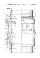
- FIG. 1 is a perspective illustrating a pipe and a connector during assembly and in a clamping tool for axially loading the connector while it is pressurized;
- FIG. 2 is a partial elevation and partial longitudinal section of one form of pipe connector, with the clamping tool broken away, and showing the connector parts stabbed together prior to final makeup;
- FIG. 3 is an enlarged fragmentary longitudinal section of the pipe connector of FIG. 2 in a fully made up and locked condition
- FIG. 4 is a reduced fragmentary section taken on the line 4--4 of FIG. 3;
- FIG. 5 is a partial elevation and partial longitudinal section of another form of pipe connector.
- a pipe connector C made in accordance with the invention, comprises an upper pin section P and a lower box section B adapted to interconnect pipe lengths, including an upper pipe section 10, secured by a circumferentially continuous weld 11 to the upper end of the pin P, and a lower pipe section 12, secured by a circumferentially continuous weld 13 to the lower end of the box section B.
- the connector C is shown and will be described as one wherein the connection is stabbed together by insertion of the downwardly extending pin into the upwardly facing box. It should be understood, however, that in the case of some uses of the connector, this relationship of pin to box may be reversed and the box moved over the pin.
- the inner, upper end of the box B is outwardly flared to facilitate stabbing of the pin into the box, and the tapered form of the parts progressively aligns the parts, as the pin moves into the box.
- the taper angle is preferably a locking angle.
- the pin section P includes a circular body section 14 having an external downwardly tapering surface 15 and a lower end surface 16 which extends transversly of the pin body 14.
- the box section B comprises a circular body section 17 having an internal downwardly tapered surface 18 complemental to the tapered surface 15 of the pin body, whereby when the pin body is inserted or stabbed into the box, the complemental tapered surfaces 15 and 18 are disposed in confronting coengagement.
- the box body 17 also includes an inner lower transversely extended shoulder or surface 19 against which the pin surface 16 abuts when the connector is made up.
- the present invention provides a joint of superior strength characteristics by reason of the fact that the pin and box sections of the joint or connector are made up in a novel manner.
- a radially extended, upwardly facing, thrust or pre-load shoulder 20 In the vicinity of the upper end of the pin body 14, it is provided with a radially extended, upwardly facing, thrust or pre-load shoulder 20, and adjacent the upper end of the box body 17, it is provided with an external radially outwardly projecting, downwardly facing, thrust shoulder 21.
- These thrust or pre-load shoulders 20 and 21 are adapted to provide means engageable by a suitable makeup or loading tool T, whereby as indicated by the respective arrows 20a and 21a in FIG. 2, a compressive axial force can be applied to the pin body 14 to load the pin end 16 against the inner box surface 19 while the box body 17 is under tension.
- the tool T may be of any suitable form to provide opposing forces as represented by the arrows 20a and 21a, and as illustrated in FIG. 1, such a tool may comprise an upper ring 22 and a lower ring 23, each of the rings 22 and 23 having suitable hinge means 24 hingedly interconnecting ring half parts together so that the ring may be opened for lateral application about the pipe and about the connector.
- Each ring 22 and 23 also is provided with suitable means, such as outstanding ears 25, at the free ends of the ring half parts, and adapted to receive bolts 26 whereby the rings 22 and 23 may be assembled and secured about the pipe and connector for engagement with the respective thrust shoulders 20 and 21 on the pin and on the box.
- the pulling means comprises a suitable number of circumferentially spaced hydraulic cylinders 27 having rods 28 projecting therefrom, with the respective cylinders connected to one of the rings as at 29 and the rods connected to the other of the rings as at 30.
- a hydraulic line 31 is adapted through suitable fittings 32 to supply hydraulic fluid under pressure to the cylinders 27 from a source conduit 33 which is connected to the conduit 31 and to a suitable fluid pressure source (not shown).
- the strength of the connector is also dependent upon the interference fit between the opposing tapered pin surface 15 and box surface 18.
- the box body 17 is provided with at least one radial pressure port 34 threaded to receive a connector fitting 35 for a hydraulic line 36, whereby fluid under pressure can be supplied between the confronting tapered surfaces 15 and 18 of the pin and box between an upper opposed sealing region 37 and a lower opposed sealing region 38 between the tapered pin and box surfaces.
- the sealing effectiveness of the upper and lower tapered, metal-to-metal sealing regions 37 and 38 may be enhanced by the provision of an upper, annular and resilient sealing ring 39 disposed in a groove 40 in the pin or the box body and a lower, annular and resilient sealing ring 41 disposed in a groove 42 in the pin or the box body, the sealing rings 39 and 41 being sealingly engaged with the opposed tapered surfaces of the respective members.
- the connector is finally made up while the fluid pressure is maintained, by actuation of the tool T to axially load the confronting pin and box surfaces 16 and 19, while the pin body 14 is under compression and the box body 17 is under tension. Accordingly, when the fluid pressure is relieved there will be effected a pressure energized interference fit between the tapered pin surface 15 and box surface 18, while the confronting transverse surfaces 16 and 19 of the pin and box are in an axially preloaded condition.
- the completed joint or connector as seen in FIG. 3, will have superior strength characteristics in terms of tensile, compressive and bending strength and a fluid tight joint is provided which is useful in making up lengths of pipe such as piles and pipelines.
- the port 34 be pluged by a suitable screw plug 34a as seen in FIG. 3.
- connection of pipe sections 10 and 12 can be easily and quickly made with the usual pipe handling equipment found on drilling barges and the like and with the pipe sections disposed vertically or at batter angles while being initially stabbed together and the making up of the connection can be accomplished more quickly than welded connections have been heretofore made.
- the invention not only provides a strong and durable connection which can withstand the severe service of subsea pipelines and piles, but economies are effected in terms of the speed with which the connections can be made up utilizing the very expensive rig or barge equipment.
- the present invention involves locking means L cooperatively engageable between the pin and the box in such a manner that the pin body section 14 is held compressively with its end surface 16 engaged with the opposing shoulder 19 of the box, and with the box body section 17 held in tension, while the tapered pin and box surfaces are coengaged by the pressure energized shrink fit, upon the relief of the pressure fluid from the region between the opposed metal-to-metal sealing sections 37 and 38.
- the locking means L comprises a plurality of circumferentially spaced locking elements 50 carried by one of the pin and box members and engaged with the other of the pin and box members to lock them together against axial separation when the compressive preload applied by the tool T and the energizing fluid pressure have been relieved.
- the box is provided with a suitable number of circumferentially spaced, radially extended internally threaded screw holes 51, adapted to receive the locking elements 50, which are in the form of externally threaded screw members having suitable tool receiving or engaging means 52 for rotating the elements 50 and causing them to be moved radially with respect to the box body 17.
- the locking elements 50 are frusto-conical nose portions 53 adapted to be engaged in companion frusto-conical recesses or seats 54 formed in the pin body 14.
- the locking elements 50 are backed out of the threaded bores 51 so that the inner ends of the noses 53 provide no obstruction to the entry of the pin P into the box.
- Radial alignment of the screws 50 with the recesses 54 is established visually or by suitable means, shown in FIG. 2 as a radially projecting pin 50a carried by the pin and engageable with a radial shoulder 50b on the box.
- a ramp 50c is provided in the pin leading downwardly from the upper end of the box to the shoulder 50b.
- the recesses 54 in the pin will be moved longitudinally relative to the box and brought into radial alignment with the locking elements 50, so that a suitable tool applied to the locking elements to rotate the same can thread the locking elements 50 inwardly causing the noses 53 to be compressively loaded into the tapered pin recesses 54.
- the connector will be interlocked by the elements 50, with the pin body 14 in compression and the box body 17 in tension, the inner end 16 of the pin being maintained in its axially preloaded condition against the box shoulder 19 and the opposing tapered pin and box surfaces 15 and 18 being tightly held together by the pressure energized interference fit.
- the locking means L comprises a plurality of elongated latch arms or fingers, integral with or made a part of the upper end of the box and extending longitudinally, in circumferentially spaced relation along an upward extension 114 of the pin body 14.
- the upward extension 114 of the pin has an upwardly facing shoulder 151 extending circumferentially thereabout, and at the respective upper end of each latch finger 150 is an inwardly projecting tip or lug 152 having a downwardly facing shoulder 153 adapted to lockingly coengage with the upper facing pin shoulder 151, as will be later described.
- this means comprises an actuator ring or body 154 having an internal square or acme thread 155 engaged with the complemental thread 156 on the reduced diameter section 114a of the upward pin body extension.
- the actuator ring or body 154 has a downwardly extended skirt 157 provided with an internal, downwardly and outwardly inclined circular wall 158 adapted to engage the upwardly and inwardly inclined surfaces 159 at the top of the latch fingers 150, whereby threaded rotation of the ring 154 on the pin will wedge the latch lugs 152 inwardly into locking coengagement with the pin shoulder 151.
- the pin shoulder 151 is disposed at an angle extending downwardly and outwardly from the reduced diameter section 114a of the body and the under surfaces or shoulders 153 of the latch lugs 152 are correspondingly inclined downwardly and outwardly to provide a wedge action, when the skirt 157 forces the lugs 152 inwardly with respect to the pin.
- This wedge action compressively loads the pin body 114 to prevent relaxation of the connector following release of the fluid pressure from between the pin and box parts and removal of the loading tool T from the connector.
- the latter is provided with a suitable stop shoulder formed by a split ring 160, seating in a circumferentially extended groove 161 below the upwardly facing thrust shoulder 20 on the pin body.
- the threaded ring 154 is threaded upwardly against the stop shoulder 160, and the locking finger elements are free at their upper ends to be resiliently deflected outwardly as the pin P is stabbed into the box B.
- the upper inner corners of the lugs 152 are downwardly and inwardly beveled at 152a, so that the fingertips will be resiliently deflected outwardly by the wedging action of the pin, as it passes between the locking fingers into the box.
- the present invention provides a pipe connector for use in making up lengths of pipe such as piles and pipelines wherein the pressure energization of the fit between the tapered pin and box members and the axial preloading of the pin P against the inner shoulder of the box while the box is held in tension results in the production of a rigidized pipe joint of superior strength and durability and which can be readily and quickly made up utilizing the usual pipe handling and supporting equipment provided on drilling rigs and barges and with the pipe sections disposed vertically or at some batter angle.
- the locking means hold the parts against axial separation.
Abstract
Description
Claims (18)
Priority Applications (1)
| Application Number | Priority Date | Filing Date | Title |
|---|---|---|---|
| US05/793,523 US4124231A (en) | 1977-05-04 | 1977-05-04 | Rigid pipe connector with radially shiftable lock elements and method of making the same |
Applications Claiming Priority (1)
| Application Number | Priority Date | Filing Date | Title |
|---|---|---|---|
| US05/793,523 US4124231A (en) | 1977-05-04 | 1977-05-04 | Rigid pipe connector with radially shiftable lock elements and method of making the same |
Publications (1)
| Publication Number | Publication Date |
|---|---|
| US4124231A true US4124231A (en) | 1978-11-07 |
Family
ID=25160105
Family Applications (1)
| Application Number | Title | Priority Date | Filing Date |
|---|---|---|---|
| US05/793,523 Expired - Lifetime US4124231A (en) | 1977-05-04 | 1977-05-04 | Rigid pipe connector with radially shiftable lock elements and method of making the same |
Country Status (1)
| Country | Link |
|---|---|
| US (1) | US4124231A (en) |
Cited By (34)
| Publication number | Priority date | Publication date | Assignee | Title |
|---|---|---|---|---|
| US4209270A (en) * | 1977-04-18 | 1980-06-24 | Hydrotech International, Inc. | Pipe connector apparatus and method |
| US4265470A (en) * | 1979-09-21 | 1981-05-05 | Cameron Iron Works, Inc. | Tubular connector |
| US4310183A (en) * | 1979-11-28 | 1982-01-12 | Raychem Corporation | Composite pipe coupling |
| US4314718A (en) * | 1979-11-28 | 1982-02-09 | Raychem Corporation | Tensile ring composite pipe coupling |
| US4453745A (en) * | 1981-08-17 | 1984-06-12 | Nelson Norman A | Lockdown mechanism for wellhead connector |
| US4479669A (en) * | 1982-04-01 | 1984-10-30 | Hydril Company | Pipe connector with threaded latch screws |
| US4629273A (en) * | 1983-03-28 | 1986-12-16 | Camp James L Van | Electrical cable connector assembly |
| US4648627A (en) * | 1984-01-18 | 1987-03-10 | Dril-Quip, Inc. | Stabbing connector |
| US5261493A (en) * | 1992-07-06 | 1993-11-16 | Abb Vetco Gray Inc. | Method of testing snap type pipe connectors |
| US5363931A (en) * | 1993-07-07 | 1994-11-15 | Schlumberger Technology Corporation | Drilling stabilizer |
| US5631563A (en) * | 1994-12-20 | 1997-05-20 | Schlumbreger Technology Corporation | Resistivity antenna shield, wear band and stabilizer assembly for measuring-while-drilling tool |
| US5899507A (en) * | 1997-02-14 | 1999-05-04 | The Pipeline Development Company | Riser fitting |
| US6106024A (en) * | 1998-06-04 | 2000-08-22 | Cooper Cameron Corporation | Riser joint and apparatus for its assembly |
| US20040134260A1 (en) * | 1999-06-28 | 2004-07-15 | Inflow Products, Inc. | Leak testing device with a permanent coupling |
| US20040134261A1 (en) * | 1999-06-28 | 2004-07-15 | Inflow Products, Inc. | Leak testing device and coupling therefor |
| US20040174015A1 (en) * | 2003-03-03 | 2004-09-09 | Price Brothers Company | Testable pipe joint |
| US20060244260A1 (en) * | 2003-08-08 | 2006-11-02 | Sigma Corporation | Joint restraint assembly |
| US7325442B1 (en) | 1999-06-28 | 2008-02-05 | Inflow Products, Ltd. | Leak testing device with a permanent coupling |
| US20080083267A1 (en) * | 1999-06-28 | 2008-04-10 | Pampinella Joseph A | Leak testing device with a permanent coupling |
| US20080157521A1 (en) * | 2007-01-03 | 2008-07-03 | Davis Joseph S | Anchor pile coupling system |
| US7398675B1 (en) | 2001-04-11 | 2008-07-15 | Securus, Inc. | Dual slide gate valve and method for using same |
| US20100037681A1 (en) * | 2008-08-15 | 2010-02-18 | Hart Dennis L | Pipe pressure testing method and apparatus |
| US20120137534A1 (en) * | 2010-12-07 | 2012-06-07 | Pierce James Barnard | Apparatus for drying clothes |
| USRE43697E1 (en) * | 1998-06-09 | 2012-10-02 | Seaboard International Inc. | Drilling quick connectors |
| WO2013022541A2 (en) | 2011-08-08 | 2013-02-14 | National Oilwell Varco, L.P. | Method and apparatus for connecting tubulars of a wellsite |
| EP2711497A1 (en) * | 2012-09-20 | 2014-03-26 | SIR MECCANICA S.p.A. | Modular shaft for machine tools |
| WO2014046859A2 (en) | 2012-09-24 | 2014-03-27 | National Oilwell Varco, L.P. | Packer assembly for an offshore riser and method of using same |
| US9022125B2 (en) | 2012-11-30 | 2015-05-05 | National Oilwell Varco, L.P. | Marine riser with side tension members |
| US20150136417A1 (en) * | 2013-11-15 | 2015-05-21 | Stingray Offshore Solutions Llc | Method for handling tubulars and rigidizer therefor |
| EP3155306A4 (en) * | 2014-06-13 | 2018-02-07 | Reliance Worldwide Corporation (Aust.) Pty. Ltd. | Adjustable connection fitting |
| US20200340306A1 (en) * | 2019-04-25 | 2020-10-29 | National Oilwell Varco Uk Limited | Connection assembly |
| US10830263B2 (en) | 2018-08-31 | 2020-11-10 | Stuart Petroleum Testers, Llc | Lubricator clamp |
| US11193337B1 (en) * | 2016-11-21 | 2021-12-07 | Pruitt Tool & Supply Co. | Method and device for connecting to a conductor pipe |
| FR3132728A1 (en) * | 2022-02-17 | 2023-08-18 | Vallourec Oil And Gas France | Threaded joint with anti-unscrewing device |
Citations (7)
| Publication number | Priority date | Publication date | Assignee | Title |
|---|---|---|---|---|
| US2147343A (en) * | 1937-11-05 | 1939-02-14 | Eidco Inc | Friction joint |
| US2671949A (en) * | 1948-11-23 | 1954-03-16 | Chicago Pneumatic Tool Co | Method of making tool joints |
| US2784987A (en) * | 1954-02-03 | 1957-03-12 | Corcoran Richard Stanley | Pipe coupling with detent means |
| US3114566A (en) * | 1961-04-21 | 1963-12-17 | Kobe Inc | Shrink fit tubing joint |
| CA700115A (en) * | 1964-12-15 | D. Johnson Glenn | Pipe coupling | |
| US3345087A (en) * | 1964-06-18 | 1967-10-03 | Ventura Company | Conduit connectors |
| US3912009A (en) * | 1974-06-12 | 1975-10-14 | Jr Philip E Davis | Latch-in adapter |
-
1977
- 1977-05-04 US US05/793,523 patent/US4124231A/en not_active Expired - Lifetime
Patent Citations (7)
| Publication number | Priority date | Publication date | Assignee | Title |
|---|---|---|---|---|
| CA700115A (en) * | 1964-12-15 | D. Johnson Glenn | Pipe coupling | |
| US2147343A (en) * | 1937-11-05 | 1939-02-14 | Eidco Inc | Friction joint |
| US2671949A (en) * | 1948-11-23 | 1954-03-16 | Chicago Pneumatic Tool Co | Method of making tool joints |
| US2784987A (en) * | 1954-02-03 | 1957-03-12 | Corcoran Richard Stanley | Pipe coupling with detent means |
| US3114566A (en) * | 1961-04-21 | 1963-12-17 | Kobe Inc | Shrink fit tubing joint |
| US3345087A (en) * | 1964-06-18 | 1967-10-03 | Ventura Company | Conduit connectors |
| US3912009A (en) * | 1974-06-12 | 1975-10-14 | Jr Philip E Davis | Latch-in adapter |
Cited By (53)
| Publication number | Priority date | Publication date | Assignee | Title |
|---|---|---|---|---|
| US4209270A (en) * | 1977-04-18 | 1980-06-24 | Hydrotech International, Inc. | Pipe connector apparatus and method |
| US4265470A (en) * | 1979-09-21 | 1981-05-05 | Cameron Iron Works, Inc. | Tubular connector |
| US4310183A (en) * | 1979-11-28 | 1982-01-12 | Raychem Corporation | Composite pipe coupling |
| US4314718A (en) * | 1979-11-28 | 1982-02-09 | Raychem Corporation | Tensile ring composite pipe coupling |
| US4453745A (en) * | 1981-08-17 | 1984-06-12 | Nelson Norman A | Lockdown mechanism for wellhead connector |
| US4479669A (en) * | 1982-04-01 | 1984-10-30 | Hydril Company | Pipe connector with threaded latch screws |
| US4629273A (en) * | 1983-03-28 | 1986-12-16 | Camp James L Van | Electrical cable connector assembly |
| US4648627A (en) * | 1984-01-18 | 1987-03-10 | Dril-Quip, Inc. | Stabbing connector |
| US5261493A (en) * | 1992-07-06 | 1993-11-16 | Abb Vetco Gray Inc. | Method of testing snap type pipe connectors |
| US5363931A (en) * | 1993-07-07 | 1994-11-15 | Schlumberger Technology Corporation | Drilling stabilizer |
| US5631563A (en) * | 1994-12-20 | 1997-05-20 | Schlumbreger Technology Corporation | Resistivity antenna shield, wear band and stabilizer assembly for measuring-while-drilling tool |
| US5899507A (en) * | 1997-02-14 | 1999-05-04 | The Pipeline Development Company | Riser fitting |
| US6106024A (en) * | 1998-06-04 | 2000-08-22 | Cooper Cameron Corporation | Riser joint and apparatus for its assembly |
| USRE43697E1 (en) * | 1998-06-09 | 2012-10-02 | Seaboard International Inc. | Drilling quick connectors |
| USRE43773E1 (en) * | 1998-06-09 | 2012-10-30 | Seaboard International Inc. | Drilling quick connectors |
| US7325442B1 (en) | 1999-06-28 | 2008-02-05 | Inflow Products, Ltd. | Leak testing device with a permanent coupling |
| US20040134261A1 (en) * | 1999-06-28 | 2004-07-15 | Inflow Products, Inc. | Leak testing device and coupling therefor |
| US20040134260A1 (en) * | 1999-06-28 | 2004-07-15 | Inflow Products, Inc. | Leak testing device with a permanent coupling |
| US20080083267A1 (en) * | 1999-06-28 | 2008-04-10 | Pampinella Joseph A | Leak testing device with a permanent coupling |
| US7398675B1 (en) | 2001-04-11 | 2008-07-15 | Securus, Inc. | Dual slide gate valve and method for using same |
| US7654287B1 (en) | 2001-04-11 | 2010-02-02 | Securus, Inc. | Dual slide gate valve and method for using same |
| US7118137B2 (en) * | 2003-03-03 | 2006-10-10 | Price Brothers Company | Testable pipe joint |
| US20040174015A1 (en) * | 2003-03-03 | 2004-09-09 | Price Brothers Company | Testable pipe joint |
| US7266875B2 (en) * | 2003-08-08 | 2007-09-11 | Sigma Corporation | Joint restraint assembly |
| US20060244260A1 (en) * | 2003-08-08 | 2006-11-02 | Sigma Corporation | Joint restraint assembly |
| US20080157521A1 (en) * | 2007-01-03 | 2008-07-03 | Davis Joseph S | Anchor pile coupling system |
| US7854451B2 (en) * | 2007-01-03 | 2010-12-21 | Davis Ii Joseph S | Anchor pile coupling system |
| US8210029B2 (en) | 2008-08-15 | 2012-07-03 | Securus, Inc. | Pipe pressure testing method and apparatus |
| US8887768B2 (en) | 2008-08-15 | 2014-11-18 | Securus, Inc. | Pipe pressure testing method and apparatus |
| US20100037681A1 (en) * | 2008-08-15 | 2010-02-18 | Hart Dennis L | Pipe pressure testing method and apparatus |
| US9964461B2 (en) | 2008-08-15 | 2018-05-08 | Reliance Worldwide Corporation | Pipe pressure testing method and apparatus |
| US10656042B2 (en) | 2008-08-15 | 2020-05-19 | Reliance Worldwide Corporation | Pipe pressure testing method and apparatus |
| US11493399B2 (en) | 2008-08-15 | 2022-11-08 | Reliance Worldwide Corporation | Pipe pressure testing method and apparatus |
| US11781934B2 (en) | 2008-08-15 | 2023-10-10 | Reliance Worldwide Corporation | Pipe pressure testing method and apparatus |
| US20120137534A1 (en) * | 2010-12-07 | 2012-06-07 | Pierce James Barnard | Apparatus for drying clothes |
| WO2013022541A3 (en) * | 2011-08-08 | 2014-01-23 | National Oilwell Varco, L.P. | Method and apparatus for connecting tubulars of a wellsite |
| EP2742204A2 (en) * | 2011-08-08 | 2014-06-18 | National Oilwell Varco, L.P. | Method and apparatus for connecting tubulars of a wellsite |
| EP2742204B1 (en) * | 2011-08-08 | 2022-10-19 | National Oilwell Varco, L.P. | Method and apparatus for connecting tubulars of a wellsite |
| EP3375972A1 (en) | 2011-08-08 | 2018-09-19 | National Oilwell Varco, L.P. | Method and apparatus for connecting tubulars of a wellsite |
| US9657536B2 (en) | 2011-08-08 | 2017-05-23 | National Oilwell Varco, L.P. | Method and apparatus for connecting tubulars of a wellsite |
| WO2013022541A2 (en) | 2011-08-08 | 2013-02-14 | National Oilwell Varco, L.P. | Method and apparatus for connecting tubulars of a wellsite |
| EP2711497A1 (en) * | 2012-09-20 | 2014-03-26 | SIR MECCANICA S.p.A. | Modular shaft for machine tools |
| US9631440B2 (en) | 2012-09-24 | 2017-04-25 | National Oilwell Varco, L.P. | Packer assembly for an offshore riser and method of using same |
| WO2014046859A2 (en) | 2012-09-24 | 2014-03-27 | National Oilwell Varco, L.P. | Packer assembly for an offshore riser and method of using same |
| US9022125B2 (en) | 2012-11-30 | 2015-05-05 | National Oilwell Varco, L.P. | Marine riser with side tension members |
| US20150136417A1 (en) * | 2013-11-15 | 2015-05-21 | Stingray Offshore Solutions Llc | Method for handling tubulars and rigidizer therefor |
| EP3155306A4 (en) * | 2014-06-13 | 2018-02-07 | Reliance Worldwide Corporation (Aust.) Pty. Ltd. | Adjustable connection fitting |
| US11193337B1 (en) * | 2016-11-21 | 2021-12-07 | Pruitt Tool & Supply Co. | Method and device for connecting to a conductor pipe |
| US10830263B2 (en) | 2018-08-31 | 2020-11-10 | Stuart Petroleum Testers, Llc | Lubricator clamp |
| US11486206B2 (en) * | 2019-04-25 | 2022-11-01 | National Oilwell Varco Uk Limited | Connection assembly |
| US20200340306A1 (en) * | 2019-04-25 | 2020-10-29 | National Oilwell Varco Uk Limited | Connection assembly |
| FR3132728A1 (en) * | 2022-02-17 | 2023-08-18 | Vallourec Oil And Gas France | Threaded joint with anti-unscrewing device |
| WO2023156479A1 (en) * | 2022-02-17 | 2023-08-24 | Vallourec Oil And Gas France | Threaded joint with unscrewing prevention device |
Similar Documents
| Publication | Publication Date | Title |
|---|---|---|
| US4124231A (en) | Rigid pipe connector with radially shiftable lock elements and method of making the same | |
| US4124233A (en) | Rigid pipe connector with lock ring and method of making the same | |
| US4124229A (en) | Rigid connector for pipe and method of making the same | |
| US4124232A (en) | Rigid pipe connector with lock elements and method of making the same | |
| US4209193A (en) | Rigid connector for large diameter pipe | |
| US4120520A (en) | Lockable rigid connector for pipe and method of making the same | |
| US4648627A (en) | Stabbing connector | |
| US3114566A (en) | Shrink fit tubing joint | |
| US4178020A (en) | Locking slip joint and method of use | |
| US4124230A (en) | Rigid pipe connector with locking screws and method of making the same | |
| US6971685B2 (en) | Multi-point high pressure seal for expandable tubular connections | |
| RU2117133C1 (en) | Connection with multiplicity of seals for vertical pipes of immersed water-separating string | |
| US4139221A (en) | Ball and socket joint | |
| US3521911A (en) | Lockable and unlockable,releasable tool joints | |
| US5071175A (en) | Pipe restrainer | |
| US3827728A (en) | Pipe connectors | |
| US3455578A (en) | Fluid pressure releasable automatic tool joint | |
| US4601491A (en) | Pipe connector | |
| US4608739A (en) | Connector of and sealing of tubular members | |
| US4012059A (en) | Pipe connector | |
| US20100187808A1 (en) | Threaded joint with pressurizable seal | |
| US5590913A (en) | Pipeline connector for connecting a branch pipe to a carrier pipe | |
| US4865359A (en) | Press fit pipe joint and method | |
| US4239266A (en) | Pipe connector apparatus | |
| NO343648B1 (en) | Rotary actuated riser connection of the tension sleeve type |
Legal Events
| Date | Code | Title | Description |
|---|---|---|---|
| AS | Assignment |
Owner name: VETCO OFFSHORE, INC. 5740 RALSTON ST.VENTURA,CA.93 Free format text: ASSIGNMENT OF ASSIGNORS INTEREST.;ASSIGNOR:VETCO INC.;REEL/FRAME:004056/0858 Effective date: 19820922 |
|
| AS | Assignment |
Owner name: VETCO OFFSHORE INDUSTRIES, INC., 7135 ARDMORE ROAD Free format text: ASSIGNMENT OF ASSIGNORS INTEREST.;ASSIGNOR:VETCO OFFSHORE, INC., A CORP. OF DE.;REEL/FRAME:004572/0533 Effective date: 19860421 |
|
| AS | Assignment |
Owner name: CITIBANK, N.A., Free format text: SECURITY INTEREST;ASSIGNOR:VETCO GRAY INC., A DE. CORP.;REEL/FRAME:004739/0780 Effective date: 19861124 |
|
| AS | Assignment |
Owner name: VETCO GRAY INC., Free format text: MERGER;ASSIGNORS:GRAY TOOL COMPANY, A TX. CORP. (INTO);VETCO OFFSHORE INDUSTRIES, INC., A CORP. (CHANGED TO);REEL/FRAME:004748/0332 Effective date: 19861217 |