US4062620A - Device for connecting optical fibers - Google Patents
Device for connecting optical fibers Download PDFInfo
- Publication number
- US4062620A US4062620A US05/665,953 US66595376A US4062620A US 4062620 A US4062620 A US 4062620A US 66595376 A US66595376 A US 66595376A US 4062620 A US4062620 A US 4062620A
- Authority
- US
- United States
- Prior art keywords
- fibers
- envelopes
- magnetic material
- end faces
- pole
- Prior art date
- Legal status (The legal status is an assumption and is not a legal conclusion. Google has not performed a legal analysis and makes no representation as to the accuracy of the status listed.)
- Expired - Lifetime
Links
- 239000013307 optical fiber Substances 0.000 title claims abstract description 11
- 239000000835 fiber Substances 0.000 claims abstract description 62
- 239000000696 magnetic material Substances 0.000 claims abstract description 13
- 239000000853 adhesive Substances 0.000 claims description 3
- 230000001070 adhesive effect Effects 0.000 claims description 3
- 230000005540 biological transmission Effects 0.000 description 4
- 238000005253 cladding Methods 0.000 description 4
- 230000008878 coupling Effects 0.000 description 4
- 238000010168 coupling process Methods 0.000 description 4
- 238000005859 coupling reaction Methods 0.000 description 4
- 238000010276 construction Methods 0.000 description 3
- 230000003287 optical effect Effects 0.000 description 3
- 230000004907 flux Effects 0.000 description 2
- 239000011521 glass Substances 0.000 description 2
- 238000004519 manufacturing process Methods 0.000 description 2
- 230000008021 deposition Effects 0.000 description 1
- 239000000428 dust Substances 0.000 description 1
- 239000007788 liquid Substances 0.000 description 1
- 238000010297 mechanical methods and process Methods 0.000 description 1
- 239000002184 metal Substances 0.000 description 1
- 238000000034 method Methods 0.000 description 1
- 239000002245 particle Substances 0.000 description 1
- 229910052710 silicon Inorganic materials 0.000 description 1
- 239000010703 silicon Substances 0.000 description 1
Images

Classifications
-
- G—PHYSICS
- G02—OPTICS
- G02B—OPTICAL ELEMENTS, SYSTEMS OR APPARATUS
- G02B6/00—Light guides; Structural details of arrangements comprising light guides and other optical elements, e.g. couplings
- G02B6/24—Coupling light guides
- G02B6/36—Mechanical coupling means
- G02B6/38—Mechanical coupling means having fibre to fibre mating means
- G02B6/3807—Dismountable connectors, i.e. comprising plugs
- G02B6/3873—Connectors using guide surfaces for aligning ferrule ends, e.g. tubes, sleeves, V-grooves, rods, pins, balls
- G02B6/3886—Magnetic means to align ferrule ends
Definitions
- the invention relates to a device for connecting i.e. coupling optical fibers.
- One of the problems governing the development of such a technique lies in the manufacture of devices for connecting optical fibers, notably a device which is easy to use, inexpensive and at the same time enables lowloss light energy transmission.
- the manufacture of such a device is difficult because the diameter of the fibers is in the order of 10 ⁇ m to 100 ⁇ m, because the fibers are fragile and because, in order to realize the optical coupling with the required transmission efficiency, the end faces of the connected fibers must be very near to each other and very accurately centered. Moreover, mechanical stresses in the fibers must be avoided.
- the invention provides a novel connection device which enables the connection of optical fibers to be made in a simple and efficient manner.
- each end of a pair of fibers to be connected is rigidly connected to a piece of magnetic material
- the connection device comprising a magnet or electromagnet having pole-shoes comprising means for guiding the said pieces of magnetic material in order to locate the end faces of said fibers one opposite the other in an air gap formed by the said poleshoes.
- the pieces which are rigidly connected to the fibers are attracted towards each other by the magnetic force of attraction, and the connection of the fibers is realized with the required accuracy due to the mechanical construction of the connection device which is adapted to provide the said accuracy.
- the pieces of magnetic material which are rigidly connected to the fibers preferably consist of cylindrical envelopes which envelop the ends of the fibers and leave the end face thereof free.
- These sleeves can be formed either by vapour deposition of magnetic material on the ends of the fibers or by securing a capillary tube around the end of each fiber by means of an adhesive.
- FIG. 1 shows the ends of two fibers which are to be connected to each other.
- FIG. 2 is a perspective view of a flat connection device in accordance with the invention.
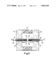
- FIG. 3 is a sectional view of a cylindrical connection device in accordance with the invention.
- FIG. 1 shows the ends of two fibers 1 and 2 which are to be connected to each other.
- the optical fibers are each formed by a core 1b, 2b having a refractive index n for the transmission of light energy, and a cladding (1a, 2a) which may have small thickness and has a refractive index n -- n.
- the core and the cladding are rotation-symmetrical, and the tolerance in the concentricity of these parts is about 1 ⁇ m. It will be assumed hereinafter that near the ends of the fibers 1 and 2 the cores and the claddings have common axes D 1 , D 2 .
- the two end faces 3 and 4 of the cores of the two fibers are in principle perpendicular to the axes D 1 , D 2 .
- a connection device for optical fibers serves to locate the said faces 3 and 4 one opposite the other and to maintain this position, so that light energy can be transferred from one fiber to the other with only low attenuation, for example, less than 0.5 dB.
- the two end faces 3 and 4 should be centered with an accuracy better than 5 ⁇ m in order to keep the attenuation smaller than 0.2 dB.
- the distance between the said end faces must be smaller than the radius of the end faces in order to keep the attenuation lower than 0.5 dB.
- the angle between the axes D 1 , D 2 must be smaller than a few degrees.
- optical coupling is not necessarily optimal due to geometrical imperfections of the fiber end faces, concentricity errors between the cores and claddings, or excessively large tolerances in the construction of the connection device. Therefore, to improve the coupling it should be readily possible to rotate one fiber with respect to the other in this device. It is also necessary to avoid mechanical stresses in the fibers in order to keep the fibers connected to each other.
- FIG. 2 illustrates an embodiment of the invention which is intended for the connection of two fibers.
- the ends of the fibers 1 and 2 are enveloped by cylindrical envelopes 5 and 6 of magnetic material which are rigidly connected to the fibers.
- the envelopes are obtained, for example, by vapour-deposition of magnetic material on the ends of the fibers.
- the end faces 3 and 4 of the fibers are situated in the same plane as the end faces 7 and 8 of the envelopes 5 and 6.
- the connection device comprises a magnet 9 having pole-shoes 10, 11.
- the side faces 12, 13 of these poleshoes form an air gap in which the magnetic flux of the magnet is concentrated.
- the upper faces of the pole-shoes 10 and 11 are provided with V-shaped grooves 14, 15 which serve as guide means for the envelopes 5 and 6 in order to locate the end faces 3 and 4 of the fibers one opposite the other in the air gap.
- the pole-shoes 10 and 11 are preferably firmly secured (using means not shown) on a non-magnetic carrier so that the two grooves can be simultaneously provided in an accurately aligned manner. It will be obvious that the end faces 7 and 8 of the magnetic envelopes, though shown at a given distance from each other in the Figure, are moved towards each other by a magnetic force of attraction and are aligned to each other by means of the said force; the same is applicable to the end faces 3 and 4 of the fibers.
- connection of the fibers is thus realized; a connection device of this kind satisfies the requirements set forth. Because the grooves can be very accurately aligned, as already described, and because the end faces of the envelopes and the fibers are accurately centered, the axes D 1 , D 2 of the two fibers will be very accurately aligned and their end faces 3 and 4 will be accurately centered.
- one metal envelope can be readily rotated with respect to the other if this proves necessary to improve the optical connection between the two fibers. It is also to be noted that the two fibers thus remain connected to each other without a mechanical device being required because the magnetic force of attraction not only keeps the end faces of the envelopes and fibers pressed against each other, but also keep these envelopes in the grooves. Finally, it is to be noted that the fibers generally are accommodated in flexible sleeves in which the fibers can move fairly freely, and that the said flexible sleeves can be secured to the connection device, for example to the pole-shoes 10, 11.
- the envelopes 5, 6 can also consist of capillary tubes which are secured around the ends of the fibers by means of an adhesive.
- the end faces 3, 4 of the fibres are not necessarily situated in the same plane as the end faces 7, 8 of the capillary tubes and can occupy, for example, a slightly withdrawn position. When the end faces 7, 8 are pulled against each other by magnetic force of attraction, a comparatively small space remains, then between the end faces 3, 4 of the fibers. Any mechanical stress is thus avoided between the ends of the fibers.
- a connection device can be realized for a plurality of pairs of optical fibers by providing the upper faces of the pole-shoes 10, 11 with a plurality of parallel grooves, the number of grooves corresponding to the number of pairs of fibers to be connected.
- the fibers of each pair can be readily connected or disconnected individually.
- the magnetic pieces which are rigidly connected to the ends of the fibers can have other shapes, provided that they are adapted to connect the two fibers to each other by magnetic attraction.
- connection device instead of the connection device as shown in FIG. 2 a connection device can be realized which has, for example, a cylindrical shape as shown in FIG. 3.
- FIG. 3 is a sectional view taken along the axis XX' of this cylindrical connection device. All parts shown are rotation-symmetrical around the said axis.
- the connection device comprises an annular magnet 20 on which the two pole-shoes 21, 22 are arranged.
- the pole-shoes comprise faces 23, 24 which are situated one opposite the other and perpendicularly to the axis XX', the said faces 23, 24 forming an air gap in which the magnetic flux of the magnet 20 in concentrated.
- Two coaxial openings are provided in the pole-shoes 21, 22 in the direction of the axis XX'.
- These openings may have a diameter adapted to the diameter of envelopes 27, 38 to constitute directly means for guiding magnetic envelopes 27, 38, or better 28- see letter, enveloping the ends of the fibers 29, 30 which are to be connected.
- the envelopes 27, 38 are preferably guided by tubes 25, 26 of non-magnetic material which are rigidly secured in the openings provided in the pole-shoes 21, 22. It has been found that the making and breaking of the connection of the fibers is thus facilitated.
- the connection of the two fibers is performed in the manner already described, by utilizing the magnetic force of attraction existing between the end faces 31, 32 of the two magnetic envelopes 27, 38. It can be stated that the ingress of dust particles into a cylindrical connection device of this kind is substantially precluded.
Abstract
A device for connecting optical fibers, the ends of which are provided with cylindrical envelopes of magnetic material which envelop the ends of the fibers and which are rigidly connected thereto. The connection device comprises a magnet having pole-shoes provided with means for guiding the said envelopes in order to position the end faces of the fibers one opposite the other in the air gap formed by the pole-shoes.
Description
The invention relates to a device for connecting i.e. coupling optical fibers.
There is a growing interest in the use of optical fibers of glass, silicon etc. for data transmission by modulation of the light energy transmitted through the said fibers.
One of the problems governing the development of such a technique lies in the manufacture of devices for connecting optical fibers, notably a device which is easy to use, inexpensive and at the same time enables lowloss light energy transmission. The manufacture of such a device is difficult because the diameter of the fibers is in the order of 10 μm to 100 μm, because the fibers are fragile and because, in order to realize the optical coupling with the required transmission efficiency, the end faces of the connected fibers must be very near to each other and very accurately centered. Moreover, mechanical stresses in the fibers must be avoided.
For known devices (for example, the device described in French Patent Specification No. 2,178,129), use is generally made of purely mechanical methods which do not fully satisfy requirements, notably in that connection is difficult to perform by non-specialized personnel.
The invention provides a novel connection device which enables the connection of optical fibers to be made in a simple and efficient manner.
In accordance with the invention, each end of a pair of fibers to be connected is rigidly connected to a piece of magnetic material, the connection device comprising a magnet or electromagnet having pole-shoes comprising means for guiding the said pieces of magnetic material in order to locate the end faces of said fibers one opposite the other in an air gap formed by the said poleshoes.
The pieces which are rigidly connected to the fibers are attracted towards each other by the magnetic force of attraction, and the connection of the fibers is realized with the required accuracy due to the mechanical construction of the connection device which is adapted to provide the said accuracy.
The pieces of magnetic material which are rigidly connected to the fibers preferably consist of cylindrical envelopes which envelop the ends of the fibers and leave the end face thereof free. These sleeves can be formed either by vapour deposition of magnetic material on the ends of the fibers or by securing a capillary tube around the end of each fiber by means of an adhesive.
Embodiments of the invention will be described by way of example with reference to the accompanying drawing wherein:
FIG. 1 shows the ends of two fibers which are to be connected to each other.
FIG. 2 is a perspective view of a flat connection device in accordance with the invention.
FIG. 3 is a sectional view of a cylindrical connection device in accordance with the invention.
FIG. 1 shows the ends of two fibers 1 and 2 which are to be connected to each other. As is known, the optical fibers are each formed by a core 1b, 2b having a refractive index n for the transmission of light energy, and a cladding (1a, 2a) which may have small thickness and has a refractive index n -- n. The core and the cladding are rotation-symmetrical, and the tolerance in the concentricity of these parts is about 1 μm. It will be assumed hereinafter that near the ends of the fibers 1 and 2 the cores and the claddings have common axes D1, D2. The two end faces 3 and 4 of the cores of the two fibers are in principle perpendicular to the axes D1, D2. A connection device for optical fibers serves to locate the said faces 3 and 4 one opposite the other and to maintain this position, so that light energy can be transferred from one fiber to the other with only low attenuation, for example, less than 0.5 dB.
This imposes a number of restrictions on the construction of the device, some of which will be given hereinafter by way of example. In the case of fibers having a diameter of 100 μm, the two end faces 3 and 4 should be centered with an accuracy better than 5 μm in order to keep the attenuation smaller than 0.2 dB. The distance between the said end faces must be smaller than the radius of the end faces in order to keep the attenuation lower than 0.5 dB. The angle between the axes D1, D2 must be smaller than a few degrees.
The optical coupling is not necessarily optimal due to geometrical imperfections of the fiber end faces, concentricity errors between the cores and claddings, or excessively large tolerances in the construction of the connection device. Therefore, to improve the coupling it should be readily possible to rotate one fiber with respect to the other in this device. It is also necessary to avoid mechanical stresses in the fibers in order to keep the fibers connected to each other.
FIG. 2 illustrates an embodiment of the invention which is intended for the connection of two fibers. In accordance with a feature of the invention, the ends of the fibers 1 and 2 are enveloped by cylindrical envelopes 5 and 6 of magnetic material which are rigidly connected to the fibers. The envelopes are obtained, for example, by vapour-deposition of magnetic material on the ends of the fibers. The end faces 3 and 4 of the fibers are situated in the same plane as the end faces 7 and 8 of the envelopes 5 and 6. The connection device comprises a magnet 9 having pole- shoes 10, 11. The side faces 12, 13 of these poleshoes form an air gap in which the magnetic flux of the magnet is concentrated. The upper faces of the pole- shoes 10 and 11 are provided with V- shaped grooves 14, 15 which serve as guide means for the envelopes 5 and 6 in order to locate the end faces 3 and 4 of the fibers one opposite the other in the air gap. The pole- shoes 10 and 11 are preferably firmly secured (using means not shown) on a non-magnetic carrier so that the two grooves can be simultaneously provided in an accurately aligned manner. It will be obvious that the end faces 7 and 8 of the magnetic envelopes, though shown at a given distance from each other in the Figure, are moved towards each other by a magnetic force of attraction and are aligned to each other by means of the said force; the same is applicable to the end faces 3 and 4 of the fibers. The connection of the fibers is thus realized; a connection device of this kind satisfies the requirements set forth. Because the grooves can be very accurately aligned, as already described, and because the end faces of the envelopes and the fibers are accurately centered, the axes D1, D2 of the two fibers will be very accurately aligned and their end faces 3 and 4 will be accurately centered.
It is to be noted that one metal envelope can be readily rotated with respect to the other if this proves necessary to improve the optical connection between the two fibers. It is also to be noted that the two fibers thus remain connected to each other without a mechanical device being required because the magnetic force of attraction not only keeps the end faces of the envelopes and fibers pressed against each other, but also keep these envelopes in the grooves. Finally, it is to be noted that the fibers generally are accommodated in flexible sleeves in which the fibers can move fairly freely, and that the said flexible sleeves can be secured to the connection device, for example to the pole- shoes 10, 11.
The envelopes 5, 6 can also consist of capillary tubes which are secured around the ends of the fibers by means of an adhesive. The end faces 3, 4 of the fibres are not necessarily situated in the same plane as the end faces 7, 8 of the capillary tubes and can occupy, for example, a slightly withdrawn position. When the end faces 7, 8 are pulled against each other by magnetic force of attraction, a comparatively small space remains, then between the end faces 3, 4 of the fibers. Any mechanical stress is thus avoided between the ends of the fibers. In any case, and notably in the latter case, it is advisable to provide a quantity of liquid having substantially the same refractive index as the glass of the fibers cores 1b, 2b on the end faces 3 and 4 of the fibers in order to avoid reflection losses on these end faces after completion of the connection.
A connection device can be realized for a plurality of pairs of optical fibers by providing the upper faces of the pole- shoes 10, 11 with a plurality of parallel grooves, the number of grooves corresponding to the number of pairs of fibers to be connected. In a connection device of this kind the fibers of each pair can be readily connected or disconnected individually.
The magnetic pieces which are rigidly connected to the ends of the fibers (and which are formed in FIG. 2 by rotation-symmetrical cylinders 5 and 6 which envelop these ends), can have other shapes, provided that they are adapted to connect the two fibers to each other by magnetic attraction.
Instead of the connection device as shown in FIG. 2 a connection device can be realized which has, for example, a cylindrical shape as shown in FIG. 3.
FIG. 3 is a sectional view taken along the axis XX' of this cylindrical connection device. All parts shown are rotation-symmetrical around the said axis. The connection device comprises an annular magnet 20 on which the two pole- shoes 21, 22 are arranged. The pole-shoes comprise faces 23, 24 which are situated one opposite the other and perpendicularly to the axis XX', the said faces 23, 24 forming an air gap in which the magnetic flux of the magnet 20 in concentrated. Two coaxial openings are provided in the pole- shoes 21, 22 in the direction of the axis XX'. These openings may have a diameter adapted to the diameter of envelopes 27, 38 to constitute directly means for guiding magnetic envelopes 27, 38, or better 28- see letter, enveloping the ends of the fibers 29, 30 which are to be connected. As is shown in FIG. 3, the envelopes 27, 38 are preferably guided by tubes 25, 26 of non-magnetic material which are rigidly secured in the openings provided in the pole- shoes 21, 22. It has been found that the making and breaking of the connection of the fibers is thus facilitated. The connection of the two fibers is performed in the manner already described, by utilizing the magnetic force of attraction existing between the end faces 31, 32 of the two magnetic envelopes 27, 38. It can be stated that the ingress of dust particles into a cylindrical connection device of this kind is substantially precluded.
It is alternatively possible to realize a cylindrical device for connecting a plurality of pairs of optical fibers on the basis of the arrangement shown in FIG. 3 by providing a plurality of openings in the sufficiently wide pole- shoes 21, 22 at the air gap, the number of openings corresponding to the number of pairs of fibers to be connected and the axes of these openings being parallel to each other.
On the basis of the described examples, it will be easy for those skilled in the art to develop other embodiments of the invention, for example utilizing poleshoes of a shape other than those described herein or other guide means.
Claims (7)
1. A device for connecting optical fibers, comprising a member of magnetic material secured to each of opposing ends of a pair of fibers to be connected, and magnetic means including spaced pole-shoes defining an air-gap therebetween each of said pole pieces having axially aligned recesses forming a guide for locating the members of magnetic material therein and thereby axially aligning the end faces of said fibers in the air gap formed by the said poleshoes, said magnetic means moving said fibers into abutting relationship in said air-gap whereby said fibers are connected to one another.
2. A device as claimed in claim 1, wherein the members of magnetic material are cylindrical envelopes which envelop the ends of the fibers and leave the end faces thereof free.
3. A device as claimed in claim 2, wherein the envelopes consist of a desposition of magnetic material around the ends of the fibers.
4. A device as claimed in claim 2, wherein each envelop comprises a capillary tube of magnetic material which is secured to the desired location around the end of its fiber by means of an adhesive.
5. A device as claimed in claim 2 wherein the poleshoes are provided with grooves for guiding the envelopes which are rigidly connected to the fibers.
6. A device as claimed in claim 2 wherein the poleshoes are provided with openings for guiding the envelopes which are rigidly connected to the fibers.
7. A device as claimed in claim 6, wherein the poleshoes form an air gap which is symmetrical about an axis extending through the pole-shoes.
Applications Claiming Priority (2)
| Application Number | Priority Date | Filing Date | Title |
|---|---|---|---|
| FR7509289A FR2305746A1 (en) | 1975-03-25 | 1975-03-25 | CONNECTOR FOR OPTICAL FIBERS |
| FR75.09289 | 1975-03-25 |
Publications (1)
| Publication Number | Publication Date |
|---|---|
| US4062620A true US4062620A (en) | 1977-12-13 |
Family
ID=9153043
Family Applications (1)
| Application Number | Title | Priority Date | Filing Date |
|---|---|---|---|
| US05/665,953 Expired - Lifetime US4062620A (en) | 1975-03-25 | 1976-03-11 | Device for connecting optical fibers |
Country Status (6)
| Country | Link |
|---|---|
| US (1) | US4062620A (en) |
| JP (1) | JPS51120734A (en) |
| DE (1) | DE2610368A1 (en) |
| FR (1) | FR2305746A1 (en) |
| GB (1) | GB1544717A (en) |
| SE (1) | SE414232B (en) |
Cited By (18)
| Publication number | Priority date | Publication date | Assignee | Title |
|---|---|---|---|---|
| US4181400A (en) * | 1976-12-31 | 1980-01-01 | Socapex | Connector with positioning sleeves for a single optical fibre |
| US4182017A (en) * | 1977-03-24 | 1980-01-08 | Lee Green Precision Industries Ltd. | Method and apparatus for terminating optical fibres |
| US4217032A (en) * | 1978-11-22 | 1980-08-12 | Sheem Sang K | End-butt optical fiber coupler |
| US4255754A (en) * | 1979-03-19 | 1981-03-10 | Xerox Corporation | Differential fiber optic sensing method and apparatus for ink jet recorders |
| US4288143A (en) * | 1978-12-28 | 1981-09-08 | Cselt - Centro Studi E Laboratori Telecomunicazioni S.P.A. | Method of and apparatus for splicing optical fibers |
| US4342847A (en) * | 1978-12-16 | 1982-08-03 | Bayer Aktiengesellschaft | Process for the production of thermoplastic synthetic materials |
| US4345137A (en) * | 1979-01-03 | 1982-08-17 | Compagnie Lyonnaise De Transmissions Optique | Method of welding several optical fibers end to end in layers and a device for welding in accordance with said method |
| US4383357A (en) * | 1981-04-16 | 1983-05-17 | Western Electric Co., Inc. | Methods of aligning paramagnetic articles |
| US4408753A (en) * | 1981-04-16 | 1983-10-11 | Western Electric Company, Inc. | Holder for aligning paramagnetic articles |
| EP0207926A2 (en) * | 1985-07-05 | 1987-01-07 | Gebauer & Griller Kabelwerke Gesellschaft m.b.H. | Dismantable connector for two light conducting components |
| US4636032A (en) * | 1983-11-10 | 1987-01-13 | Cselt Centro Studi E Laboratori Telecomunicazioni S.P.A. | Optical fibre connector |
| US4648168A (en) * | 1983-12-19 | 1987-03-10 | N.V. Raychem S.A. | Optical fibre breakout |
| US4657341A (en) * | 1983-08-03 | 1987-04-14 | Siemens Aktiengesellschaft | Connector for light waveguides and method of producing same |
| US4807960A (en) * | 1986-04-19 | 1989-02-28 | U.S. Philips Corp. | Device for pair-wise coupling the ends of two groups of optical fibers |
| US5015061A (en) * | 1987-12-09 | 1991-05-14 | Giannini Gabriel M | Optical connector |
| EP0559364A1 (en) * | 1992-03-02 | 1993-09-08 | Motorola, Inc. | Magnetic holding methods for optical fiber I/O assembly |
| US5261015A (en) * | 1991-11-21 | 1993-11-09 | Ametek, Inc. | Magnetically-actuatable opto-mechanical on/off switch and systems for use therewith |
| US20130108216A1 (en) * | 2011-10-27 | 2013-05-02 | Tyco Electronics Corporation | Optical fiber having core-to-core alignment |
Families Citing this family (14)
| Publication number | Priority date | Publication date | Assignee | Title |
|---|---|---|---|---|
| JPS5237443A (en) * | 1975-09-20 | 1977-03-23 | Showa Electric Wire & Cable Co Ltd | Junction part of optical fiber cables and process for connection there of |
| DE2654653C3 (en) * | 1976-12-02 | 1981-12-10 | Siemens AG, 1000 Berlin und 8000 München | Device for aligning and releasably attaching light guides to a support plate |
| JPS54130042A (en) * | 1978-03-30 | 1979-10-09 | Boeicho Gijutsu Kenkyu Honbuch | Optical fiber connector |
| IT1107327B (en) * | 1978-04-26 | 1985-11-25 | Cselt Centro Studi Lab Telecom | MAGNETIC ONLECTOR FOR OPTICAL CABLES |
| JPS5553306A (en) * | 1978-10-17 | 1980-04-18 | Nippon Telegr & Teleph Corp <Ntt> | Connecting method of optical fiber |
| JPS5533196A (en) * | 1979-08-20 | 1980-03-08 | Showa Electric Wire & Cable Co Ltd | Splicing method of optical fiber cable |
| US4244681A (en) * | 1979-12-31 | 1981-01-13 | International Business Machines Corporation | Magnetic fiber optic casting apparatus |
| JPS5753714A (en) * | 1980-09-16 | 1982-03-30 | Nippon Telegr & Teleph Corp <Ntt> | Optical fiber connector |
| JPS61112106A (en) * | 1985-07-26 | 1986-05-30 | Dainichi Nippon Cables Ltd | Welding connection device of optical fiber |
| DE3731946A1 (en) * | 1987-09-23 | 1989-04-13 | Kurt Dr Sauerwein | MAGNETIC COUPLING |
| GB8805015D0 (en) * | 1988-03-02 | 1988-03-30 | British Telecomm | Optical fibre locating apparatus |
| DE3921344A1 (en) * | 1989-06-29 | 1991-01-10 | Hengstler Gmbh | External data programming unit - has magnetically latched cable coupling providing communication with programmable controller |
| GB9011506D0 (en) * | 1990-05-23 | 1990-07-11 | Bicc Plc | Optical fibre fusion splicing |
| DE10306323A1 (en) * | 2003-02-14 | 2004-09-02 | Siemens Ag | Device for tensioning and rotating a light-conducting fiber, splicing device |
Citations (2)
| Publication number | Priority date | Publication date | Assignee | Title |
|---|---|---|---|---|
| US3112360A (en) * | 1962-06-15 | 1963-11-26 | Winston Res Corp | Scanning with light-conducting rod |
| US3912574A (en) * | 1974-10-24 | 1975-10-14 | Bell Telephone Labor Inc | Apparatus for splicing pairs of arrayed or individual fibers utilizing optical fiber aligning grooves |
-
1975
- 1975-03-25 FR FR7509289A patent/FR2305746A1/en active Granted
-
1976
- 1976-03-11 US US05/665,953 patent/US4062620A/en not_active Expired - Lifetime
- 1976-03-12 DE DE19762610368 patent/DE2610368A1/en not_active Withdrawn
- 1976-03-22 SE SE7603476A patent/SE414232B/en unknown
- 1976-03-22 GB GB11413/76A patent/GB1544717A/en not_active Expired
- 1976-03-24 JP JP51032391A patent/JPS51120734A/en active Pending
Patent Citations (2)
| Publication number | Priority date | Publication date | Assignee | Title |
|---|---|---|---|---|
| US3112360A (en) * | 1962-06-15 | 1963-11-26 | Winston Res Corp | Scanning with light-conducting rod |
| US3912574A (en) * | 1974-10-24 | 1975-10-14 | Bell Telephone Labor Inc | Apparatus for splicing pairs of arrayed or individual fibers utilizing optical fiber aligning grooves |
Non-Patent Citations (2)
| Title |
|---|
| Leighton, "Fiber Optic Shutter," IBM Tech. Disc. Bulletin, vol. 11, No. 8, Jan. 1969, pp. 912-913. * |
| Zemon et al., "Eccentric Coupler for Optical Fibers . . .," Appl. Optics, vol. 14, No. 4, Apr. 1975, pp. 815-816. * |
Cited By (21)
| Publication number | Priority date | Publication date | Assignee | Title |
|---|---|---|---|---|
| US4181400A (en) * | 1976-12-31 | 1980-01-01 | Socapex | Connector with positioning sleeves for a single optical fibre |
| US4182017A (en) * | 1977-03-24 | 1980-01-08 | Lee Green Precision Industries Ltd. | Method and apparatus for terminating optical fibres |
| US4217032A (en) * | 1978-11-22 | 1980-08-12 | Sheem Sang K | End-butt optical fiber coupler |
| US4342847A (en) * | 1978-12-16 | 1982-08-03 | Bayer Aktiengesellschaft | Process for the production of thermoplastic synthetic materials |
| US4288143A (en) * | 1978-12-28 | 1981-09-08 | Cselt - Centro Studi E Laboratori Telecomunicazioni S.P.A. | Method of and apparatus for splicing optical fibers |
| US4345137A (en) * | 1979-01-03 | 1982-08-17 | Compagnie Lyonnaise De Transmissions Optique | Method of welding several optical fibers end to end in layers and a device for welding in accordance with said method |
| US4255754A (en) * | 1979-03-19 | 1981-03-10 | Xerox Corporation | Differential fiber optic sensing method and apparatus for ink jet recorders |
| US4383357A (en) * | 1981-04-16 | 1983-05-17 | Western Electric Co., Inc. | Methods of aligning paramagnetic articles |
| US4408753A (en) * | 1981-04-16 | 1983-10-11 | Western Electric Company, Inc. | Holder for aligning paramagnetic articles |
| US4657341A (en) * | 1983-08-03 | 1987-04-14 | Siemens Aktiengesellschaft | Connector for light waveguides and method of producing same |
| US4636032A (en) * | 1983-11-10 | 1987-01-13 | Cselt Centro Studi E Laboratori Telecomunicazioni S.P.A. | Optical fibre connector |
| US4648168A (en) * | 1983-12-19 | 1987-03-10 | N.V. Raychem S.A. | Optical fibre breakout |
| EP0207926A2 (en) * | 1985-07-05 | 1987-01-07 | Gebauer & Griller Kabelwerke Gesellschaft m.b.H. | Dismantable connector for two light conducting components |
| EP0207926A3 (en) * | 1985-07-05 | 1988-04-06 | Gebauer & Griller Kabelwerke Gesellschaft M.B.H. | Dismantable connector for two light or electricity conducting components |
| US4807960A (en) * | 1986-04-19 | 1989-02-28 | U.S. Philips Corp. | Device for pair-wise coupling the ends of two groups of optical fibers |
| US5015061A (en) * | 1987-12-09 | 1991-05-14 | Giannini Gabriel M | Optical connector |
| US5261015A (en) * | 1991-11-21 | 1993-11-09 | Ametek, Inc. | Magnetically-actuatable opto-mechanical on/off switch and systems for use therewith |
| EP0559364A1 (en) * | 1992-03-02 | 1993-09-08 | Motorola, Inc. | Magnetic holding methods for optical fiber I/O assembly |
| US5276762A (en) * | 1992-03-02 | 1994-01-04 | Motorola, Inc. | Magnetic holding methods for optical fiber I/O assembly |
| US20130108216A1 (en) * | 2011-10-27 | 2013-05-02 | Tyco Electronics Corporation | Optical fiber having core-to-core alignment |
| US9028153B2 (en) * | 2011-10-27 | 2015-05-12 | Tyco Electronics Corporation | Optical fiber having core-to-core alignment |
Also Published As
| Publication number | Publication date |
|---|---|
| SE414232B (en) | 1980-07-14 |
| DE2610368A1 (en) | 1976-10-07 |
| SE7603476L (en) | 1976-09-26 |
| FR2305746B1 (en) | 1977-11-18 |
| FR2305746A1 (en) | 1976-10-22 |
| JPS51120734A (en) | 1976-10-22 |
| GB1544717A (en) | 1979-04-25 |
Similar Documents
| Publication | Publication Date | Title |
|---|---|---|
| US4062620A (en) | Device for connecting optical fibers | |
| US5596662A (en) | Multichannel optical connection method for optical fibers | |
| US3919037A (en) | Optical fiber splicing apparatus | |
| CN101779149B (en) | Hole arranged photonic crystal fiber for low loss, tight fiber bending applications | |
| US3917383A (en) | Optical waveguide bundle connector | |
| CA1113760A (en) | Magnetic connector for optical cables | |
| GB2046942A (en) | Optical star coupler for multi-mode light conducting fibres | |
| US4798428A (en) | Fiber optic coupling system | |
| US4123138A (en) | Optical fiber connector | |
| JPH02188706A (en) | Optical fiber coupler | |
| Miller | Loose tube splices for optical fibers | |
| US7024090B2 (en) | Optical fiber array with variable fiber angle alignment and method for the fabrication thereof | |
| JPS63183405A (en) | Planar optical circuit and assembly with optical fiber connected thereto | |
| US4402568A (en) | Method and apparatus for an optical four-gate coupler | |
| EP0145937B1 (en) | Optical-fibre connector | |
| US20030202737A1 (en) | Optical switch | |
| CN113721323B (en) | Novel multi-core optical fiber coupling device and preparation method | |
| US4244681A (en) | Magnetic fiber optic casting apparatus | |
| CN211856985U (en) | Multichannel array optical isolator | |
| US3887264A (en) | Optical fiber with asymmetric index profile | |
| CN202075526U (en) | Photoisolator | |
| CN214067437U (en) | Optical circulator integrating beam expanding function | |
| Jaccard et al. | A new technique for low cost all-fiber device fabrication | |
| JPS6051088B2 (en) | optical distribution circuit | |
| US20030231820A1 (en) | Optical switch |