US4030143A - Endoprosthetic bone joint devices - Google Patents
Endoprosthetic bone joint devices Download PDFInfo
- Publication number
- US4030143A US4030143A US05/653,524 US65352476A US4030143A US 4030143 A US4030143 A US 4030143A US 65352476 A US65352476 A US 65352476A US 4030143 A US4030143 A US 4030143A
- Authority
- US
- United States
- Prior art keywords
- cup
- ball
- component
- rim
- engaged
- Prior art date
- Legal status (The legal status is an assumption and is not a legal conclusion. Google has not performed a legal analysis and makes no representation as to the accuracy of the status listed.)
- Expired - Lifetime
Links
Images

Classifications
-
- A—HUMAN NECESSITIES
- A61—MEDICAL OR VETERINARY SCIENCE; HYGIENE
- A61F—FILTERS IMPLANTABLE INTO BLOOD VESSELS; PROSTHESES; DEVICES PROVIDING PATENCY TO, OR PREVENTING COLLAPSING OF, TUBULAR STRUCTURES OF THE BODY, e.g. STENTS; ORTHOPAEDIC, NURSING OR CONTRACEPTIVE DEVICES; FOMENTATION; TREATMENT OR PROTECTION OF EYES OR EARS; BANDAGES, DRESSINGS OR ABSORBENT PADS; FIRST-AID KITS
- A61F2/00—Filters implantable into blood vessels; Prostheses, i.e. artificial substitutes or replacements for parts of the body; Appliances for connecting them with the body; Devices providing patency to, or preventing collapsing of, tubular structures of the body, e.g. stents
- A61F2/02—Prostheses implantable into the body
- A61F2/30—Joints
- A61F2/40—Joints for shoulders
-
- A—HUMAN NECESSITIES
- A61—MEDICAL OR VETERINARY SCIENCE; HYGIENE
- A61F—FILTERS IMPLANTABLE INTO BLOOD VESSELS; PROSTHESES; DEVICES PROVIDING PATENCY TO, OR PREVENTING COLLAPSING OF, TUBULAR STRUCTURES OF THE BODY, e.g. STENTS; ORTHOPAEDIC, NURSING OR CONTRACEPTIVE DEVICES; FOMENTATION; TREATMENT OR PROTECTION OF EYES OR EARS; BANDAGES, DRESSINGS OR ABSORBENT PADS; FIRST-AID KITS
- A61F2/00—Filters implantable into blood vessels; Prostheses, i.e. artificial substitutes or replacements for parts of the body; Appliances for connecting them with the body; Devices providing patency to, or preventing collapsing of, tubular structures of the body, e.g. stents
- A61F2/02—Prostheses implantable into the body
- A61F2/30—Joints
- A61F2002/30001—Additional features of subject-matter classified in A61F2/28, A61F2/30 and subgroups thereof
- A61F2002/30108—Shapes
- A61F2002/3011—Cross-sections or two-dimensional shapes
- A61F2002/30138—Convex polygonal shapes
- A61F2002/30148—Convex polygonal shapes lozenge- or diamond-shaped
-
- A—HUMAN NECESSITIES
- A61—MEDICAL OR VETERINARY SCIENCE; HYGIENE
- A61F—FILTERS IMPLANTABLE INTO BLOOD VESSELS; PROSTHESES; DEVICES PROVIDING PATENCY TO, OR PREVENTING COLLAPSING OF, TUBULAR STRUCTURES OF THE BODY, e.g. STENTS; ORTHOPAEDIC, NURSING OR CONTRACEPTIVE DEVICES; FOMENTATION; TREATMENT OR PROTECTION OF EYES OR EARS; BANDAGES, DRESSINGS OR ABSORBENT PADS; FIRST-AID KITS
- A61F2/00—Filters implantable into blood vessels; Prostheses, i.e. artificial substitutes or replacements for parts of the body; Appliances for connecting them with the body; Devices providing patency to, or preventing collapsing of, tubular structures of the body, e.g. stents
- A61F2/02—Prostheses implantable into the body
- A61F2/30—Joints
- A61F2002/30001—Additional features of subject-matter classified in A61F2/28, A61F2/30 and subgroups thereof
- A61F2002/30621—Features concerning the anatomical functioning or articulation of the prosthetic joint
- A61F2002/30649—Ball-and-socket joints
-
- A—HUMAN NECESSITIES
- A61—MEDICAL OR VETERINARY SCIENCE; HYGIENE
- A61F—FILTERS IMPLANTABLE INTO BLOOD VESSELS; PROSTHESES; DEVICES PROVIDING PATENCY TO, OR PREVENTING COLLAPSING OF, TUBULAR STRUCTURES OF THE BODY, e.g. STENTS; ORTHOPAEDIC, NURSING OR CONTRACEPTIVE DEVICES; FOMENTATION; TREATMENT OR PROTECTION OF EYES OR EARS; BANDAGES, DRESSINGS OR ABSORBENT PADS; FIRST-AID KITS
- A61F2/00—Filters implantable into blood vessels; Prostheses, i.e. artificial substitutes or replacements for parts of the body; Appliances for connecting them with the body; Devices providing patency to, or preventing collapsing of, tubular structures of the body, e.g. stents
- A61F2/02—Prostheses implantable into the body
- A61F2/30—Joints
- A61F2/40—Joints for shoulders
- A61F2/4014—Humeral heads or necks; Connections of endoprosthetic heads or necks to endoprosthetic humeral shafts
- A61F2002/4018—Heads or epiphyseal parts of humerus
- A61F2002/4022—Heads or epiphyseal parts of humerus having a concave shape, e.g. hemispherical cups
-
- A—HUMAN NECESSITIES
- A61—MEDICAL OR VETERINARY SCIENCE; HYGIENE
- A61F—FILTERS IMPLANTABLE INTO BLOOD VESSELS; PROSTHESES; DEVICES PROVIDING PATENCY TO, OR PREVENTING COLLAPSING OF, TUBULAR STRUCTURES OF THE BODY, e.g. STENTS; ORTHOPAEDIC, NURSING OR CONTRACEPTIVE DEVICES; FOMENTATION; TREATMENT OR PROTECTION OF EYES OR EARS; BANDAGES, DRESSINGS OR ABSORBENT PADS; FIRST-AID KITS
- A61F2/00—Filters implantable into blood vessels; Prostheses, i.e. artificial substitutes or replacements for parts of the body; Appliances for connecting them with the body; Devices providing patency to, or preventing collapsing of, tubular structures of the body, e.g. stents
- A61F2/02—Prostheses implantable into the body
- A61F2/30—Joints
- A61F2/40—Joints for shoulders
- A61F2/4081—Glenoid components, e.g. cups
- A61F2002/4085—Glenoid components, e.g. cups having a convex shape, e.g. hemispherical heads
-
- A—HUMAN NECESSITIES
- A61—MEDICAL OR VETERINARY SCIENCE; HYGIENE
- A61F—FILTERS IMPLANTABLE INTO BLOOD VESSELS; PROSTHESES; DEVICES PROVIDING PATENCY TO, OR PREVENTING COLLAPSING OF, TUBULAR STRUCTURES OF THE BODY, e.g. STENTS; ORTHOPAEDIC, NURSING OR CONTRACEPTIVE DEVICES; FOMENTATION; TREATMENT OR PROTECTION OF EYES OR EARS; BANDAGES, DRESSINGS OR ABSORBENT PADS; FIRST-AID KITS
- A61F2230/00—Geometry of prostheses classified in groups A61F2/00 - A61F2/26 or A61F2/82 or A61F9/00 or A61F11/00 or subgroups thereof
- A61F2230/0002—Two-dimensional shapes, e.g. cross-sections
- A61F2230/0017—Angular shapes
Definitions
- This invention concerns endoprosthetic bone joint devices and more particularly, but not exclusively, such devices for the shoulder joint.
- the shoulder joint has, of all the major joints, the greatest range of movement and two thirds of this movement occurs at the ball-and-socket joint between the humerus and scapula.
- This last joint has been the subject of various proposals for endoprosthetic devices, but none so far appear to satisfy adequately the basic requirements for such a device.
- Requirements (3) and (4) are inter-related because early mobilization of the joint is required to ensure a full range of movement, but this is only possible if the prosthesis has inherent stability. Lack of stability allows dislocation with consequent disruption and subsequent stiffening of the newly forming fibrous capsule and other healing soft tissue, and such damage not only extends the recovery time but results ultimately in a reduced range of movement.
- a small head type which is similar to the anatomical type but employs a smaller headed humeral component bearing with a hemispherically cupped scapular component. This deeper cup goes some way to improving joint stability, but invariably the centre of rotation is unnaturally close to the scapula and restricts the range of movement by improper relationship with muscle attachments and also by contact between the humerus and the acromion and caracoid processes of the scapula.
- a reverse anatomical type which is also similar to the anatomical type but with a hemispherically cupped humeral component and a ball scapular component. This gives normal joint function together with the improved stability of a more deeply cupped component, but the reversed geometry places a much greater strain on the scapular component fixation. This last deficiency is particularly significant since, in rheumatoid arthritic joints, bone erosion can leave little material for fixation of scapular components. Indeed, in some cases the glenoid cavity hardly exists and the remaining joint function is exercised between the humeral head and the acromion and caracoid processes.
- An object of the present invention is to provide an endoprosthetic device which can better satisfy the above requirements, and such a device comprises: a first component in the form of a substantially spherically shaped ball connected through a necked portion to an elongate stem; a second component in the form of a cup having an interior surface with complementary shaping to said ball, said interior surface extending over an area less than that of said ball but greater than a hemisphere, said cup having at least one resilient rim portion to allow engagement of said ball therein, and said cup having an exterior surface with a relieved configuration; and a third component in the form of a clip adapted to extend around said exterior surface, to engage with said relieved configuration, and to hold each said rim portion against movement allowing disengagement of said ball from said cup.
- the ball and cup are engaged, this engagement is held against dislocation by engagement of the clip with the cup, and the overall assembly is implanted with the first component being secured by way of its stem in one bone of the relevant joint and with the cup and clip being secured in the other bone of the joint with use of cement.
- This last step involves bonding the clip with the exterior surface of the cup by mutual encapsulation in cement, and so the ball and cup engagement is firmly secured against dislocation.
- the present device has been developed for application to the shoulder joint and for this purpose it it intended that a reversed anatomical configuration be used with the first component stem cemented in a channel formed in the thickened bone along the lateral margins of the scapula to afford fixation adequate to meet the higher stresses of this configuration.
- the cup has main interior surface area which is no greater than hemispherical, but is extended by two diametrally-opposed secondary surface areas provided by respective lug-like integral formations at the rim of the cup.
- the proposed device additionally comprises:
- This second cup can be held in position by a fifth component in the form of a further clip engageable around the second cup and with at least one of the first cup and the first-mentioned clip.
- the second cup can be held in position by way of a mutual snap fit with another component of the device.
- the two cups can be formed to effect a mutual snap fit around the ball, conveniently by appropriate shaping of the above-mentioned lug formations in the first cup and the complementary formations in the second cup.
- the second cup snaps around the necked portion of the first component.
- This addition serves to constrain the ball between the two cups so that the components are held in a consistent positional relationship during fixation, whereafter the second cup is removed to allow articulation.
- the second cup also services to maintain the articulatory surfaces free from cement.
- first clip may be omitted and the first cup be simply engaged by a snap fit, in similar manner to the second clip and cup.
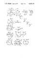
- FIGS. 1 and 2 are mutually perpendicular side views of the first component of the relevant embodiment
- FIGS. 3 to 7 are sectional views respectively taken at 1--1 to V--V in FIG. 1,
- FIGS. 8 to 10 respectively illustrate the associated second component in one end view, a side view, and the opposite end view
- FIGS. 11 to 13 respectively illustrate the associated third component in three mutually perpendicular elevation views
- FIGS. 14 and 15 respectively illustrate associated fourth and fifth components in perspective and side elevation views
- FIGS. 16 and 17 respectively illustrate in anterior and lateral views the components when assembled and located relative to the scapula and humerus.
- the illustrated first component is of integral metal construction denoted generally at 20 and comprises a spherically shaped ball 21 leading through a necked portion 22 to a stem 23.
- the ball 21 is of about 20 mm diameter and is connected to the narrower end of the necked portion 22, the latter being of frustoconical shape.
- the stem 23 is of tapered form connected in off-set overlapping manner with the necked portion 22 at their wider ends. Also the stem is longitudinally curved over its wider end portion so that its narrower end portion has its longitudinal axis angled at about 45° to that of necked portion 22, the latter axis being, in turn, diametrally located relative to the ball 21.
- the wider, curved end portion of the stem 23 has a sectional shaping which is of generally round-ended, rectangular form as shown by FIG. 4, while the remainder of the stem is of relatively reduced, tapering form with generally diamond sectional shape as shown by FIGS. 5 to 7.
- the illustrated second component is the ⁇ first ⁇ cup, of integral plastics material construction, and denoted generally at 30.
- the cup 30 has a main body portion 31 of hemispherical shape and uniform thickness to define interior and exterior surfaces 32 and 33 of which the former has the same diameter as the ball 20, and a planar rim surface 34.
- Two like, diametrally-opposed lugs 35 extend integrally from the rim surface 34, the interior and exterior surfaces 32 and 33 continuing smoothly across these lugs with respectively spherical and cylindrical shaping.
- the remaining features of the cup 30 comprise grooves formed in the exterior surface 33.
- a first such groove 36 is of annular form located parallel to the rim surface 34, while three further grooves 37 are disposed orthogonally to groove 36 in the medial plane of the cup relative to the lugs 35. Two of the grooves 37 extend similarly over respective ones of the lugs 35 to communicate with the groove 36, and the third groove 37 extends across the region of the exterior surface 33 furthest from the rim surface 34.
- the illustrated third component is the ⁇ first ⁇ clip and is denoted generally at 40.
- This clip comprises a metal rod formed to a rectangular U-shape with arms 41 and base 42.
- the clip rod is of circular sectional shape having a diameter equal to the width of grooves 37.
- the clip arms 41 are each formed with a bore 43 passing diametrally therethrough adjacent its free end, these bores being axially aligned.
- the illustrated fourth component is the ⁇ second ⁇ cup and is of integral plastics material construction denoted generally at 50.
- the cup 50 is of similar shape to the first cup 30 in having hemispherical interior and exterior surfaces 51 and 52 of like diameter to those of cup 30, and a planar rim surface 53.
- the exterior surface 52 has only a single groove 54 located similarly to the third one of grooves 37 in the first cup, and the rim surface 53 has no lugs. Instead the rim surface is formed with three notches. Two of these notches 55 are complementary to the lugs 35, and the third notch 56 is generally complementary to the cross-sectional shape of the necked portion 22 adjacent the ball 21.
- the illustrated fifth component is the ⁇ second ⁇ clip and is denoted generally at 60.
- This clip 60 is of metal wire formed to comprise a main body portion 61 of generally semi-circular shape, and two radially-inwardly-projecting, free-end portions 62.
- the wire of clip 60 has circular sectional shape of like diameter to the first clip bores 43 and the second cup groove 54, and the diameter of the main body portion is substantially equal to that of the exterior surface 52 of the second cup.
- the ball 21 is snapped into the first cup 30, the material of the cup 30 being of such resilience and the lugs being of such dimensions as to allow this engagement.
- This ball-and-cup engagement is then rendered captive by locating the first clip 40 around the cup 30 with the clip arms 41 engaged in the grooves 37 extending over the lugs 35, and with the clip base 42 engaged in the remaining groove 37.
- the clip 40 is resilient to allow its location as just described, but the resultant force required to remove the ball from the clipped first cup is clearly significantly greater than that to engage the ball in the cup without its clip.
- the first and second components are relatively positioned, by mutual articulation of the ball and first cup, so that the second cup 50 can be located over the ball with the cup rim surfaces 34 and 53 abutted, with the lugs 35 received in the notches 55, and with the necked portion 22 accommodated in the notch 56.
- This location of the second cup is then held by engagement of the second clip 60 around the second cup with the main body portion of this clip received in the second cup groove 54, and with end portions 62 of the second clip sprung into the bores 43 of the first clip.
- the second cup can be held in location by a snap fit as mentioned earlier.
- the components are intended to be used in the assembled form just described and a preferred operative procedure involves a standard anterior approach in the delto-pectoral groove, with the incision being extended by dividing the anterior third of the deltoid from its scapular insertion.
- the subscapularis is divided and the joint opened through an anterior incision in the capsule.
- the articular surfaces are assessed and the head of the humerus removed through the anatomical neck.
- the glenoid fossa is deepened using a small gouge and Volkmann spoon and the deepening is extended down the auxiliary border of the scapula using a finger down this border as a director.
- the track is completed using the stem of a trial prosthesis.
- a bed is then prepared in the humerus for the first cup and clip of the prosthesis and a trial reduction made.
- this is removed and bone cement pressed into the stem bed in the scapula and the stem of the prosthesis to be implanted is pressed firmly into position and held until the cement has set.
- a further trial reduction of the humerus to the latter prosthesis is made before pressing cement in the humeral bed and reducing the humerus to receive the first cup and clip in full external rotation. This reduction is held until the cement has set, surplus cement being removed during this time.
- the second cup and clip are then removed and the range of articulation checked before closing the wound in layers with drainage.
- the assembled device is shown relative to the humerus 70 and scapula 80 in FIGS. 16 and 17, the former being an anterior view but with the humeral components misplaced for clarity of illustration of the overall assembly, and the latter being a lateral view with the assembly in full external rotation relative to the scapula.
Abstract
A ball-and-socket joint prosthesis developed for the shoulder has one component in the form of a ball connected through a neck to a stem, a first cup engaged with the ball in a snap fit which is held captive by a first clip connected round the cup, and a second cup releasably engaged around the remainder of the ball. The second cup is slotted from its rim to accommodate the first component neck and so predetermine the relative positions of these parts, and the second cup rim is complementary with that of the first cup to predetermine the relative positions of the cups around the ball. The resultant assembly therefore fixes the relative positions of the one component and first cup to facilitate securement of these parts, while keeping the articular surfaces free of cement, and the second cup is removed after securement to leave a stable captive ball-and-socket joint.
Description
This invention concerns endoprosthetic bone joint devices and more particularly, but not exclusively, such devices for the shoulder joint.
The shoulder joint has, of all the major joints, the greatest range of movement and two thirds of this movement occurs at the ball-and-socket joint between the humerus and scapula. This last joint has been the subject of various proposals for endoprosthetic devices, but none so far appear to satisfy adequately the basic requirements for such a device. These requirements can be summarized as:
1. Involve a simple operative procedure causing minimal trauma.
2. Allow sound fixation, even in badly eroded bone.
3. Provide correct anatomical function with a full range of movement.
4. Entail innate stability to compensate for loss of natural constraints.
Requirements (3) and (4) are inter-related because early mobilization of the joint is required to ensure a full range of movement, but this is only possible if the prosthesis has inherent stability. Lack of stability allows dislocation with consequent disruption and subsequent stiffening of the newly forming fibrous capsule and other healing soft tissue, and such damage not only extends the recovery time but results ultimately in a reduced range of movement.
The prior proposals mentioned above have led to three basic types of device, as follows:
A. An Anatomical type in which the humeral head is replaced by a component of the same geometry, commonly of metal and usually secured by way of an intramedullary stem, while the scapular glenoid is substituted by a correspondingly shallow lining of metal or plastics material secured by short members penetrating the scapular. This type gives normal function but does nothing to rectify lost joint integrity due to degenerated musculature and ligaments.
B. A small head type which is similar to the anatomical type but employs a smaller headed humeral component bearing with a hemispherically cupped scapular component. This deeper cup goes some way to improving joint stability, but invariably the centre of rotation is unnaturally close to the scapula and restricts the range of movement by improper relationship with muscle attachments and also by contact between the humerus and the acromion and caracoid processes of the scapula.
C. A reverse anatomical type which is also similar to the anatomical type but with a hemispherically cupped humeral component and a ball scapular component. This gives normal joint function together with the improved stability of a more deeply cupped component, but the reversed geometry places a much greater strain on the scapular component fixation. This last deficiency is particularly significant since, in rheumatoid arthritic joints, bone erosion can leave little material for fixation of scapular components. Indeed, in some cases the glenoid cavity hardly exists and the remaining joint function is exercised between the humeral head and the acromion and caracoid processes.
An object of the present invention is to provide an endoprosthetic device which can better satisfy the above requirements, and such a device comprises: a first component in the form of a substantially spherically shaped ball connected through a necked portion to an elongate stem; a second component in the form of a cup having an interior surface with complementary shaping to said ball, said interior surface extending over an area less than that of said ball but greater than a hemisphere, said cup having at least one resilient rim portion to allow engagement of said ball therein, and said cup having an exterior surface with a relieved configuration; and a third component in the form of a clip adapted to extend around said exterior surface, to engage with said relieved configuration, and to hold each said rim portion against movement allowing disengagement of said ball from said cup.
In the more general use of the proposed device, the ball and cup are engaged, this engagement is held against dislocation by engagement of the clip with the cup, and the overall assembly is implanted with the first component being secured by way of its stem in one bone of the relevant joint and with the cup and clip being secured in the other bone of the joint with use of cement. This last step involves bonding the clip with the exterior surface of the cup by mutual encapsulation in cement, and so the ball and cup engagement is firmly secured against dislocation.
As intimated by the initial introduction above, the present device has been developed for application to the shoulder joint and for this purpose it it intended that a reversed anatomical configuration be used with the first component stem cemented in a channel formed in the thickened bone along the lateral margins of the scapula to afford fixation adequate to meet the higher stresses of this configuration. Also it is preferred for this purpose that the cup has main interior surface area which is no greater than hemispherical, but is extended by two diametrally-opposed secondary surface areas provided by respective lug-like integral formations at the rim of the cup.
It is further preferred that the proposed device additionally comprises:
a fourth component in the form of a cup having a rim substantially complementary to that of the first-mentioned cup, and having an interior surface engageable around the ball in diametrically opposed location to the first cup with the two cup rims engaged, the second-mentioned cup being slotted from its rim to accommodate the necked portion of said first component. This second cup can be held in position by a fifth component in the form of a further clip engageable around the second cup and with at least one of the first cup and the first-mentioned clip. Alternatively, the second cup can be held in position by way of a mutual snap fit with another component of the device. For example, the two cups can be formed to effect a mutual snap fit around the ball, conveniently by appropriate shaping of the above-mentioned lug formations in the first cup and the complementary formations in the second cup. In another such arrangement, which is to be employed in a current clinical trial, the second cup snaps around the necked portion of the first component.
This addition serves to constrain the ball between the two cups so that the components are held in a consistent positional relationship during fixation, whereafter the second cup is removed to allow articulation. The second cup also services to maintain the articulatory surfaces free from cement.
It is also possible that the first clip may be omitted and the first cup be simply engaged by a snap fit, in similar manner to the second clip and cup.
A fuller understanding of the invention will be gained by consideration of the following description of the presently preferred shoulder joint embodiment thereof with reference to the accompanying drawings, in which:
FIGS. 1 and 2 are mutually perpendicular side views of the first component of the relevant embodiment,
FIGS. 3 to 7 are sectional views respectively taken at 1--1 to V--V in FIG. 1,
FIGS. 8 to 10 respectively illustrate the associated second component in one end view, a side view, and the opposite end view,
FIGS. 11 to 13 respectively illustrate the associated third component in three mutually perpendicular elevation views,
FIGS. 14 and 15 respectively illustrate associated fourth and fifth components in perspective and side elevation views, and
FIGS. 16 and 17 respectively illustrate in anterior and lateral views the components when assembled and located relative to the scapula and humerus.
The illustrated first component is of integral metal construction denoted generally at 20 and comprises a spherically shaped ball 21 leading through a necked portion 22 to a stem 23. The ball 21 is of about 20 mm diameter and is connected to the narrower end of the necked portion 22, the latter being of frustoconical shape. The stem 23 is of tapered form connected in off-set overlapping manner with the necked portion 22 at their wider ends. Also the stem is longitudinally curved over its wider end portion so that its narrower end portion has its longitudinal axis angled at about 45° to that of necked portion 22, the latter axis being, in turn, diametrally located relative to the ball 21. It will also be seen that the wider, curved end portion of the stem 23 has a sectional shaping which is of generally round-ended, rectangular form as shown by FIG. 4, while the remainder of the stem is of relatively reduced, tapering form with generally diamond sectional shape as shown by FIGS. 5 to 7.
The illustrated second component is the `first` cup, of integral plastics material construction, and denoted generally at 30. The cup 30 has a main body portion 31 of hemispherical shape and uniform thickness to define interior and exterior surfaces 32 and 33 of which the former has the same diameter as the ball 20, and a planar rim surface 34. Two like, diametrally-opposed lugs 35 extend integrally from the rim surface 34, the interior and exterior surfaces 32 and 33 continuing smoothly across these lugs with respectively spherical and cylindrical shaping.
The remaining features of the cup 30 comprise grooves formed in the exterior surface 33. A first such groove 36 is of annular form located parallel to the rim surface 34, while three further grooves 37 are disposed orthogonally to groove 36 in the medial plane of the cup relative to the lugs 35. Two of the grooves 37 extend similarly over respective ones of the lugs 35 to communicate with the groove 36, and the third groove 37 extends across the region of the exterior surface 33 furthest from the rim surface 34.
The illustrated third component is the `first` clip and is denoted generally at 40. This clip comprises a metal rod formed to a rectangular U-shape with arms 41 and base 42. The clip rod is of circular sectional shape having a diameter equal to the width of grooves 37. Also, the clip arms 41 are each formed with a bore 43 passing diametrally therethrough adjacent its free end, these bores being axially aligned.
The illustrated fourth component is the `second` cup and is of integral plastics material construction denoted generally at 50. The cup 50 is of similar shape to the first cup 30 in having hemispherical interior and exterior surfaces 51 and 52 of like diameter to those of cup 30, and a planar rim surface 53. However, the exterior surface 52 has only a single groove 54 located similarly to the third one of grooves 37 in the first cup, and the rim surface 53 has no lugs. Instead the rim surface is formed with three notches. Two of these notches 55 are complementary to the lugs 35, and the third notch 56 is generally complementary to the cross-sectional shape of the necked portion 22 adjacent the ball 21.
The illustrated fifth component is the `second` clip and is denoted generally at 60. This clip 60 is of metal wire formed to comprise a main body portion 61 of generally semi-circular shape, and two radially-inwardly-projecting, free-end portions 62. The wire of clip 60 has circular sectional shape of like diameter to the first clip bores 43 and the second cup groove 54, and the diameter of the main body portion is substantially equal to that of the exterior surface 52 of the second cup.
In assembly of the illustrated embodiments, the ball 21 is snapped into the first cup 30, the material of the cup 30 being of such resilience and the lugs being of such dimensions as to allow this engagement. This ball-and-cup engagement is then rendered captive by locating the first clip 40 around the cup 30 with the clip arms 41 engaged in the grooves 37 extending over the lugs 35, and with the clip base 42 engaged in the remaining groove 37. Again, the clip 40 is resilient to allow its location as just described, but the resultant force required to remove the ball from the clipped first cup is clearly significantly greater than that to engage the ball in the cup without its clip. Thereafter, the first and second components are relatively positioned, by mutual articulation of the ball and first cup, so that the second cup 50 can be located over the ball with the cup rim surfaces 34 and 53 abutted, with the lugs 35 received in the notches 55, and with the necked portion 22 accommodated in the notch 56. This location of the second cup is then held by engagement of the second clip 60 around the second cup with the main body portion of this clip received in the second cup groove 54, and with end portions 62 of the second clip sprung into the bores 43 of the first clip. In addition, or alternatively, the second cup can be held in location by a snap fit as mentioned earlier.
The components are intended to be used in the assembled form just described and a preferred operative procedure involves a standard anterior approach in the delto-pectoral groove, with the incision being extended by dividing the anterior third of the deltoid from its scapular insertion. The subscapularis is divided and the joint opened through an anterior incision in the capsule. The articular surfaces are assessed and the head of the humerus removed through the anatomical neck. The glenoid fossa is deepened using a small gouge and Volkmann spoon and the deepening is extended down the auxiliary border of the scapula using a finger down this border as a director. The track is completed using the stem of a trial prosthesis. Using a gouge and spoon, a bed is then prepared in the humerus for the first cup and clip of the prosthesis and a trial reduction made. When sufficient bone has been removed from the scapula and humerus to allow satisfactory reduction with the trial prosthesis, this is removed and bone cement pressed into the stem bed in the scapula and the stem of the prosthesis to be implanted is pressed firmly into position and held until the cement has set. A further trial reduction of the humerus to the latter prosthesis is made before pressing cement in the humeral bed and reducing the humerus to receive the first cup and clip in full external rotation. This reduction is held until the cement has set, surplus cement being removed during this time. The second cup and clip are then removed and the range of articulation checked before closing the wound in layers with drainage.
The assembled device is shown relative to the humerus 70 and scapula 80 in FIGS. 16 and 17, the former being an anterior view but with the humeral components misplaced for clarity of illustration of the overall assembly, and the latter being a lateral view with the assembly in full external rotation relative to the scapula.
The advantages of the illustrated embodiment and its use as just described are that: it is appropriate to employ a simple operative procedure requiring no special instrumentation and causing no undue trauma; a good range of articulation is possible, with up to 135° abduction and 110° flexion: inherent joint stability is provided, allowing early mobilization with speedy recovery and reduced likelihood of subsequent decrease in range of movement; sound scapular fixation can be effected even in cases with severe rheumatoid arthritic erosion; consistent relative positioning of the prosthesis components is maintained during fixation; cement is restrained from access to the articular surfaces; and the implanted first clip serves as a radiological marker for the first cup.
In conclusion it is to be noted that these advantages are not exclusive to the illustrated embodiment, but can be provided by other forms of the invention within the scope of the appendant claims. Also, while the invention has been developed in relation to the shoulder joint, the invention can find advantageous application in other joints, such as the hip, where ball-and-socket prosthetic devices are employed.
Claims (8)
1. An endoprosthetic bone joint device comprising:
a first component in the form of a substantially spherically shaped ball connected through a necked portion to an elongate stem;
a second component in the form of a cup having an interior surface with complementary shaping to and engaged with said ball, said interior surface extending over an area less than that of said ball but greater than a hemisphere, said cup having at least one resilient rim portion to allow engagement of said ball therein, and said cup having an exterior surface with a relieved configuration;
a third component in the form of a clip extending around said exterior surface, engaged with said relieved configuration, and holding each said rim portion captively engaged with said ball; and
a fourth component in the form of a second cup having a rim substantially complementary to that of the first-mentioned cup, having an interior surface engaged around said ball in diametrally opposed location to said first cup with the two cup rims engaged, being slotted from its rim to accommodate said necked portion, and being releasably held in a predetermined positional relationship with said first and second components.
2. A device according to claim 1 wherein said second component cup has two of said rim portions comprising respective diametrally opposed lugs, the main body of the interior surface of such cup being no greater than hemispherical but being extended beyond a hemisphere by said lugs.
3. A device according to claim 2 wherein said relieved configuration comprises grooves extending circumferentially around said exterior surface and along said lugs, and said clip comprises a U-shaped structure seated in said grooves and embracing said lugs.
4. A device according to claim 1 for use as a humero-scapular replacement with said first and second components respectively adapted as scapular and humeral components, said first component having said necked portion extending substantially diametrally from said ball, and said stem being of tapered, longitudinally curved form with its wider end connected to said necked portion in transversely off-set manner.
5. A device according to claim 1 wherein the exterior surface of said second cup has a relieved configuration, and said device comprises a second clip engaging such configuration and releasably connected with one of said second and third components.
6. A device according to claim 1 wherein said second cup is held in a mutual snap fit with one of said first and second components.
7. A device according to claim 6 wherein said first and fourth components effect a mutual snap fit between said necked portion and said slot accommodating the same.
8. An endoprosthetic bone joint device comprising:
a first component in the form of a ball connected through a neck to the wider end of a tapered stem;
a first cup engaged with said ball by a mutual snap fit to form a ball and socket joint;
and a second cup held in releasable engagement with said ball, said second cup being slotted from its rim to accommodate said neck and predetermine the relative positions of said second cup and said ball, and the rim of said first and second cups being complementary and abutted to predetermine the positions of said cups relative to each other.
Applications Claiming Priority (2)
| Application Number | Priority Date | Filing Date | Title |
|---|---|---|---|
| GB4421/75A GB1544403A (en) | 1975-01-31 | 1975-01-31 | Endoprosthetic bone joint devices |
| UK04421/75 | 1975-01-31 |
Publications (1)
| Publication Number | Publication Date |
|---|---|
| US4030143A true US4030143A (en) | 1977-06-21 |
Family
ID=9776873
Family Applications (1)
| Application Number | Title | Priority Date | Filing Date |
|---|---|---|---|
| US05/653,524 Expired - Lifetime US4030143A (en) | 1975-01-31 | 1976-01-29 | Endoprosthetic bone joint devices |
Country Status (3)
| Country | Link |
|---|---|
| US (1) | US4030143A (en) |
| GB (1) | GB1544403A (en) |
| IE (1) | IE42258B1 (en) |
Cited By (64)
| Publication number | Priority date | Publication date | Assignee | Title |
|---|---|---|---|---|
| US4718911A (en) * | 1986-02-19 | 1988-01-12 | Pfizer Hospital Products Group Inc. | Acetabular cup assembly |
| US4784663A (en) * | 1986-02-19 | 1988-11-15 | Pfizer Hospital Products Group, Inc. | Acetabular cup assembly |
| US4865609A (en) * | 1988-03-02 | 1989-09-12 | Bioconcepts, Inc. | Modular joint prosthesis assembly and method of removing |
| US5282865A (en) * | 1992-06-22 | 1994-02-01 | Osteonics Corp. | Humeral shoulder prosthesis |
| DE4314200C1 (en) * | 1993-04-30 | 1994-07-28 | Eska Medical Gmbh & Co | Shoulder joint endoprosthesis |
| US5358531A (en) * | 1990-06-12 | 1994-10-25 | British Technology Group Limited | Prosthetic knee joint devices |
| EP0720839A1 (en) * | 1995-01-03 | 1996-07-10 | Tornier Sa | Femoral shaft with twisted profile for hip prosthesis |
| US5741335A (en) * | 1994-12-08 | 1998-04-21 | Cedior | Total shoulder prosthesis |
| US5776194A (en) * | 1996-04-25 | 1998-07-07 | Nuvana Medical Innovations, Llc | Intermedullary rod apparatus and methods of repairing proximal humerus fractures |
| US5961555A (en) * | 1998-03-17 | 1999-10-05 | Huebner; Randall J. | Modular shoulder prosthesis |
| US20020177901A1 (en) * | 2001-05-25 | 2002-11-28 | Howie Donald W. | Prosthetic implant |
| US6494913B1 (en) | 1998-03-17 | 2002-12-17 | Acumed, Inc. | Shoulder prosthesis |
| US20040230197A1 (en) * | 2003-03-10 | 2004-11-18 | Alain Tornier | Ancillary tool for positioning a glenoid implant |
| US20050049709A1 (en) * | 2003-08-25 | 2005-03-03 | Alain Tornier | Glenoid component of a shoulder prosthesis and complete shoulder prosthesis incorporating such a component |
| US20050090832A1 (en) * | 1997-01-31 | 2005-04-28 | Masini Michael A. | Shoulder prosthesis with anatomic reattachment features |
| US20050165490A1 (en) * | 2003-12-19 | 2005-07-28 | Alain Tornier | Shoulder or hip prosthesis and process for fitting same |
| US20050197708A1 (en) * | 2001-07-11 | 2005-09-08 | Stone Kevin T. | Shoulder prosthesis |
| US20050278031A1 (en) * | 2004-06-15 | 2005-12-15 | Tomier | Set of humeral components for total shoulder prosthesis |
| US20050278033A1 (en) * | 2004-06-15 | 2005-12-15 | Alain Tornier | Total shoulder prosthesis or inverted type |
| US20050278030A1 (en) * | 2004-06-15 | 2005-12-15 | Tornier | Glenoidal component, set of such components and shoulder prosthesis incorporating such a glenoidal component |
| US20050278032A1 (en) * | 2004-06-15 | 2005-12-15 | Tornier | Glenoidal component of a shoulder prosthesis, set of elements constituting such a component and total shoulder prosthesis incorporating such a component |
| US20060020344A1 (en) * | 2002-07-10 | 2006-01-26 | Biomet Manufacturing Corp. | Shoulder implant assembly |
| US7175663B1 (en) | 2003-10-08 | 2007-02-13 | Biomet Manufacturing Corp. | Shoulder implant assembly |
| WO2007041879A1 (en) * | 2005-10-13 | 2007-04-19 | Plus Orthopedics Ag | Inverse design of endoprosthesis for shoulder joints |
| US20070112430A1 (en) * | 2005-11-16 | 2007-05-17 | Simmen Beat R | Endoprosthesis for a shoulder joint |
| US20070173945A1 (en) * | 2006-01-20 | 2007-07-26 | Zimmer Technology, Inc. | Shoulder arthroplasty system |
| US20070225821A1 (en) * | 2006-03-21 | 2007-09-27 | Axiom Orthopaedics, Inc. | Femoral and humeral stem geometry and implantation method for orthopedic joint reconstruction |
| US20070225818A1 (en) * | 2006-03-21 | 2007-09-27 | Axiom Orthopaedics, Inc. | Non-spherical articulating surfaces in shoulder and hip replacement |
| US20070225817A1 (en) * | 2006-03-21 | 2007-09-27 | Reubelt Leo M | Glenoid component with improved fixation stability |
| US20080114461A1 (en) * | 2006-11-13 | 2008-05-15 | Howmedica Osteonics Corp. | Modular humeral head |
| US20080183297A1 (en) * | 2007-01-30 | 2008-07-31 | Tornier | Method and apparatus for fitting a shoulder prosthesis |
| US20080208348A1 (en) * | 2005-02-11 | 2008-08-28 | Wolfgang Fitz | Apparatus and Method for Shoulder Arthroplasty |
| US20080221697A1 (en) * | 2007-03-06 | 2008-09-11 | Robert Graser | Hemi-implant for first metatarsophalangeal joint |
| US20080228281A1 (en) * | 2005-09-16 | 2008-09-18 | Zimmer Gmbh | Insert and Shell of a Joint Ball Receptacle |
| US20080294268A1 (en) * | 2005-11-18 | 2008-11-27 | Zimmer Gmbh | Base Platform for an Artificial Joint |
| US7470287B2 (en) | 2004-06-28 | 2008-12-30 | Tornier Sas | Shoulder or hip prosthesis |
| US20090099662A1 (en) * | 2007-10-12 | 2009-04-16 | Howmedica Osteonics Corp. | Expandable reverse shoulder trial |
| US20090187251A1 (en) * | 2002-04-25 | 2009-07-23 | Zimmer Technology, Inc. | Modular bone implant, tools, and method |
| US20090192621A1 (en) * | 2003-10-08 | 2009-07-30 | Biomet Manufacturing Corp. | Shoulder Implant Assembly |
| US20110035014A1 (en) * | 2006-01-20 | 2011-02-10 | Zimmer Gmbh | Humeral component |
| US20110218638A1 (en) * | 2010-03-08 | 2011-09-08 | Zafer Termanini | Interlocking Reverse Hip and Revision Prosthesis |
| US20110264153A1 (en) * | 2010-04-27 | 2011-10-27 | Michel Hassler | Intra-articular joint replacement and method |
| US8080063B2 (en) | 2006-04-13 | 2011-12-20 | Tornier Sas | Glenoid component with an anatomically optimized keel |
| US8110005B2 (en) | 2000-04-10 | 2012-02-07 | Biomet Manufacturing Corp. | Modular prosthesis and use thereof for replacing a radial head |
| US20120239156A1 (en) * | 2011-03-18 | 2012-09-20 | Depuy Products, Inc. | Revision glenoid device and method |
| US8277511B2 (en) | 2006-04-21 | 2012-10-02 | Tornier Sas | Shoulder or hip prosthesis and method for setting same |
| US8535382B2 (en) | 2000-04-10 | 2013-09-17 | Biomet Manufacturing, Llc | Modular radial head prostheses |
| US20140025173A1 (en) * | 2012-07-23 | 2014-01-23 | Tornier Orthopedics Ireland Ltd. | Glenoid implants having adjustable base plates |
| US8663334B2 (en) | 2012-05-31 | 2014-03-04 | Howmedica Osteonics Corp. | Lateral entry insert for cup trial |
| US8702804B2 (en) | 2011-12-02 | 2014-04-22 | Biomet Manufacturing, Llc | Variable prosthesis |
| US8764836B2 (en) | 2011-03-18 | 2014-07-01 | Lieven de Wilde | Circular glenoid method for shoulder arthroplasty |
| US8795379B2 (en) | 2001-07-11 | 2014-08-05 | Biomet Manufacturing, Llc | Variable prosthesis |
| US8845750B2 (en) | 2011-05-16 | 2014-09-30 | Jerome A. Slavitt | Joint resurfacing prosthetic implant system |
| US8906102B2 (en) | 2012-05-31 | 2014-12-09 | Howmedica Osteonics Corp. | Lateral entry insert for cup trial |
| US8920509B2 (en) | 2000-04-10 | 2014-12-30 | Biomet Manufacturing, Llc | Modular radial head prosthesis |
| US8974536B2 (en) | 2007-01-30 | 2015-03-10 | Tornier Sas | Intra-articular joint replacement |
| US9226830B2 (en) | 2011-03-18 | 2016-01-05 | DePuy Synthes Products, Inc. | Device and method for retroversion correction for shoulder arthroplasty |
| US9421106B2 (en) | 2011-12-07 | 2016-08-23 | Howmedica Osteonics Corp. | Reverse shoulder baseplate with alignment guide for glenosphere |
| US9763679B2 (en) | 2011-03-18 | 2017-09-19 | DePuy Synthes Products, Inc. | Combination driver/anti-rotation handle for shoulder arthroplasty |
| US9820758B2 (en) | 2011-03-18 | 2017-11-21 | DePuy Synthes Products, Inc. | Combination reamer/drill bit for shoulder arthoplasty |
| US9918854B2 (en) | 2011-03-16 | 2018-03-20 | Smith & Nephew, Inc. | Compound angle implant |
| US10390972B2 (en) | 2016-01-15 | 2019-08-27 | Howmedica Osteonics Corp. | Humeral trial adaptor |
| US10631993B2 (en) | 2010-10-22 | 2020-04-28 | Tornier, Inc. | Set of glenoid components for a shoulder prosthesis |
| US11439512B2 (en) * | 2016-12-06 | 2022-09-13 | Tornier | Glenohumeral component for a shoulder prosthesis, and shoulder prosthesis comprising such a glenohumeral component |
Families Citing this family (1)
| Publication number | Priority date | Publication date | Assignee | Title |
|---|---|---|---|---|
| CA1240101A (en) * | 1983-05-06 | 1988-08-09 | Michael J. Pappas | Multi-component prosthesis with increased wall flexibility facilitating component assembly |
Citations (4)
| Publication number | Priority date | Publication date | Assignee | Title |
|---|---|---|---|---|
| GB1362187A (en) * | 1970-07-21 | 1974-07-30 | Univ Leeds | Shoulder surgery |
| US3842442A (en) * | 1972-09-04 | 1974-10-22 | Nat Res Dev | Endoprosthetic shoulder joint |
| US3863273A (en) * | 1973-09-20 | 1975-02-04 | Meditec Inc | Orthopedic prosthetic implant devices |
| US3916451A (en) * | 1974-10-25 | 1975-11-04 | Frederick F Buechel | Floating center prosthetic joint |
-
1975
- 1975-01-31 GB GB4421/75A patent/GB1544403A/en not_active Expired
-
1976
- 1976-01-29 US US05/653,524 patent/US4030143A/en not_active Expired - Lifetime
- 1976-01-30 IE IE187/76A patent/IE42258B1/en unknown
Patent Citations (4)
| Publication number | Priority date | Publication date | Assignee | Title |
|---|---|---|---|---|
| GB1362187A (en) * | 1970-07-21 | 1974-07-30 | Univ Leeds | Shoulder surgery |
| US3842442A (en) * | 1972-09-04 | 1974-10-22 | Nat Res Dev | Endoprosthetic shoulder joint |
| US3863273A (en) * | 1973-09-20 | 1975-02-04 | Meditec Inc | Orthopedic prosthetic implant devices |
| US3916451A (en) * | 1974-10-25 | 1975-11-04 | Frederick F Buechel | Floating center prosthetic joint |
Cited By (156)
| Publication number | Priority date | Publication date | Assignee | Title |
|---|---|---|---|---|
| US4718911A (en) * | 1986-02-19 | 1988-01-12 | Pfizer Hospital Products Group Inc. | Acetabular cup assembly |
| US4784663A (en) * | 1986-02-19 | 1988-11-15 | Pfizer Hospital Products Group, Inc. | Acetabular cup assembly |
| US4865609A (en) * | 1988-03-02 | 1989-09-12 | Bioconcepts, Inc. | Modular joint prosthesis assembly and method of removing |
| US5358531A (en) * | 1990-06-12 | 1994-10-25 | British Technology Group Limited | Prosthetic knee joint devices |
| US5480446A (en) * | 1990-06-12 | 1996-01-02 | British Technology Group Ltd. | Prosthetic knee joint devices |
| US5282865A (en) * | 1992-06-22 | 1994-02-01 | Osteonics Corp. | Humeral shoulder prosthesis |
| DE4314200C1 (en) * | 1993-04-30 | 1994-07-28 | Eska Medical Gmbh & Co | Shoulder joint endoprosthesis |
| EP0622062A1 (en) * | 1993-04-30 | 1994-11-02 | ESKA Implants GmbH & Co. | Shoulder prothesis |
| US5741335A (en) * | 1994-12-08 | 1998-04-21 | Cedior | Total shoulder prosthesis |
| EP0720839A1 (en) * | 1995-01-03 | 1996-07-10 | Tornier Sa | Femoral shaft with twisted profile for hip prosthesis |
| USRE43482E1 (en) * | 1996-04-25 | 2012-06-19 | Nuvana Medical Innovations, Llc | Intramedullary rod apparatus and methods of repairing proximal humerus fractures |
| US5776194A (en) * | 1996-04-25 | 1998-07-07 | Nuvana Medical Innovations, Llc | Intermedullary rod apparatus and methods of repairing proximal humerus fractures |
| US7229478B2 (en) * | 1997-01-31 | 2007-06-12 | Medidea, Llc | Shoulder prosthesis with anatomic reattachment features |
| US20050090832A1 (en) * | 1997-01-31 | 2005-04-28 | Masini Michael A. | Shoulder prosthesis with anatomic reattachment features |
| US7297163B2 (en) | 1998-03-17 | 2007-11-20 | Acumed Llc | Shoulder prosthesis |
| US6102953A (en) * | 1998-03-17 | 2000-08-15 | Acumed, Inc. | Shoulder prosthesis |
| US6168627B1 (en) | 1998-03-17 | 2001-01-02 | Acumed, Inc. | Shoulder prosthesis |
| US6168628B1 (en) | 1998-03-17 | 2001-01-02 | Acumed, Inc. | Shoulder Prosthesis |
| US6193758B1 (en) | 1998-03-17 | 2001-02-27 | Acumed, Inc. | Shoulder prosthesis |
| US6494913B1 (en) | 1998-03-17 | 2002-12-17 | Acumed, Inc. | Shoulder prosthesis |
| US7918892B2 (en) | 1998-03-17 | 2011-04-05 | Acumed Llc | Shoulder prosthesis |
| US5961555A (en) * | 1998-03-17 | 1999-10-05 | Huebner; Randall J. | Modular shoulder prosthesis |
| US8366781B2 (en) | 2000-04-10 | 2013-02-05 | Biomet Manufacturing Corp. | Modular prosthesis and use thereof for replacing a radial head |
| US9439784B2 (en) | 2000-04-10 | 2016-09-13 | Biomet Manufacturing, Llc | Modular radial head prosthesis |
| US9333084B2 (en) | 2000-04-10 | 2016-05-10 | Biomet Manufacturing, Llc | Modular prosthesis and use thereof for replacing a radial head |
| US9579208B2 (en) | 2000-04-10 | 2017-02-28 | Biomet Manufacturing, Llc | Modular radial head prosthesis |
| US8114163B2 (en) | 2000-04-10 | 2012-02-14 | Biomet Manufacturing Corp. | Method and apparatus for adjusting height and angle for a radial head |
| US8920509B2 (en) | 2000-04-10 | 2014-12-30 | Biomet Manufacturing, Llc | Modular radial head prosthesis |
| US8425615B2 (en) | 2000-04-10 | 2013-04-23 | Biomet Manufacturing Corp. | Method and apparatus for adjusting height and angle for a radial head |
| US8110005B2 (en) | 2000-04-10 | 2012-02-07 | Biomet Manufacturing Corp. | Modular prosthesis and use thereof for replacing a radial head |
| US8535382B2 (en) | 2000-04-10 | 2013-09-17 | Biomet Manufacturing, Llc | Modular radial head prostheses |
| US6994731B2 (en) * | 2001-05-25 | 2006-02-07 | Howie Donald W | Prosthetic implant |
| US20020177901A1 (en) * | 2001-05-25 | 2002-11-28 | Howie Donald W. | Prosthetic implant |
| US20050197708A1 (en) * | 2001-07-11 | 2005-09-08 | Stone Kevin T. | Shoulder prosthesis |
| US7819923B2 (en) | 2001-07-11 | 2010-10-26 | Biomet Manufacturing Corp. | Shoulder prosthesis |
| US8795379B2 (en) | 2001-07-11 | 2014-08-05 | Biomet Manufacturing, Llc | Variable prosthesis |
| US10603181B2 (en) | 2001-07-11 | 2020-03-31 | Biomet Manufacturing, Llc | Shoulder prosthesis |
| US9700423B2 (en) | 2001-07-11 | 2017-07-11 | Biomet Manufacturing, Llc | Shoulder prosthesis |
| US8906103B2 (en) | 2001-07-11 | 2014-12-09 | Biomet Manufacturing, Llc | Shoulder prosthesis |
| US20110035015A1 (en) * | 2001-07-11 | 2011-02-10 | Biomet Manufacturing Corp. | Shoulder prothesis |
| US8236059B2 (en) | 2001-07-11 | 2012-08-07 | Biomet Manufacturing, Inc. | Shoulder prothesis |
| US9241803B2 (en) | 2001-07-11 | 2016-01-26 | Biomet Manufacturing, Llc. | Shoulder prosthesis |
| US20090187251A1 (en) * | 2002-04-25 | 2009-07-23 | Zimmer Technology, Inc. | Modular bone implant, tools, and method |
| US8075628B2 (en) | 2002-04-25 | 2011-12-13 | Zimmer, Inc. | Modular bone implant, tools, and method |
| US20060020344A1 (en) * | 2002-07-10 | 2006-01-26 | Biomet Manufacturing Corp. | Shoulder implant assembly |
| US8062376B2 (en) | 2002-07-10 | 2011-11-22 | Biomet Manufacturing Corp. | Shoulder implant assembly |
| US20040230197A1 (en) * | 2003-03-10 | 2004-11-18 | Alain Tornier | Ancillary tool for positioning a glenoid implant |
| US20070250174A1 (en) * | 2003-03-10 | 2007-10-25 | Tornier | Ancillary tool for positioning a glenoid implant |
| US8187282B2 (en) | 2003-03-10 | 2012-05-29 | Tornier Sas | Ancillary tool for positioning a glenoid implant |
| US7887544B2 (en) | 2003-03-10 | 2011-02-15 | Tornier Sas | Ancillary tool for positioning a glenoid implant |
| US20050049709A1 (en) * | 2003-08-25 | 2005-03-03 | Alain Tornier | Glenoid component of a shoulder prosthesis and complete shoulder prosthesis incorporating such a component |
| US8070820B2 (en) | 2003-10-08 | 2011-12-06 | Biomet Manufacturing Corp. | Shoulder implant assembly |
| US9283083B2 (en) | 2003-10-08 | 2016-03-15 | Biomet Manufacturing, Llc | Shoulder implant assembly |
| US7175663B1 (en) | 2003-10-08 | 2007-02-13 | Biomet Manufacturing Corp. | Shoulder implant assembly |
| US20090192621A1 (en) * | 2003-10-08 | 2009-07-30 | Biomet Manufacturing Corp. | Shoulder Implant Assembly |
| US7621961B2 (en) | 2003-10-08 | 2009-11-24 | Biomet Manufacturing Corp. | Shoulder implant assembly |
| US20070142918A1 (en) * | 2003-10-08 | 2007-06-21 | Stone Kevin T | Shoulder implant assembly |
| US7465319B2 (en) | 2003-12-19 | 2008-12-16 | Tornier Sas | Shoulder or hip prosthesis and process for fitting same |
| US20050165490A1 (en) * | 2003-12-19 | 2005-07-28 | Alain Tornier | Shoulder or hip prosthesis and process for fitting same |
| US11523907B2 (en) | 2004-06-15 | 2022-12-13 | Tornier Sas | Glenoidal component, set of such components and shoulder prosthesis incorporating such a glenoidal component |
| US20050278030A1 (en) * | 2004-06-15 | 2005-12-15 | Tornier | Glenoidal component, set of such components and shoulder prosthesis incorporating such a glenoidal component |
| US10610363B2 (en) | 2004-06-15 | 2020-04-07 | Tornier Sas | Glenoidal component, set of such components and shoulder prosthesis incorporating such a glenoidal component |
| US7462197B2 (en) | 2004-06-15 | 2008-12-09 | Tornier Sas | Glenoidal component of a shoulder prosthesis, set of elements constituting such a component and total shoulder prosthesis incorporating such a component |
| US7678150B2 (en) | 2004-06-15 | 2010-03-16 | Tornier Sas | Total shoulder prosthesis of an inverted type |
| US20050278031A1 (en) * | 2004-06-15 | 2005-12-15 | Tomier | Set of humeral components for total shoulder prosthesis |
| US7309360B2 (en) | 2004-06-15 | 2007-12-18 | Tornier | Set of humeral components for total shoulder prosthesis |
| US20050278033A1 (en) * | 2004-06-15 | 2005-12-15 | Alain Tornier | Total shoulder prosthesis or inverted type |
| US9545312B2 (en) | 2004-06-15 | 2017-01-17 | Tornier Sas | Glenoidal component, set of such components and shoulder prosthesis incorporating such a glenoidal component |
| US20050278032A1 (en) * | 2004-06-15 | 2005-12-15 | Tornier | Glenoidal component of a shoulder prosthesis, set of elements constituting such a component and total shoulder prosthesis incorporating such a component |
| US8303665B2 (en) | 2004-06-15 | 2012-11-06 | Tornier Sas | Glenoidal component, set of such components and shoulder prosthesis incorporating such a glenoidal component |
| US7470287B2 (en) | 2004-06-28 | 2008-12-30 | Tornier Sas | Shoulder or hip prosthesis |
| US20080208348A1 (en) * | 2005-02-11 | 2008-08-28 | Wolfgang Fitz | Apparatus and Method for Shoulder Arthroplasty |
| US8608805B2 (en) | 2005-09-16 | 2013-12-17 | Zimmer Gmbh | Insert and shell of a joint ball receptacle |
| US20080228281A1 (en) * | 2005-09-16 | 2008-09-18 | Zimmer Gmbh | Insert and Shell of a Joint Ball Receptacle |
| WO2007041879A1 (en) * | 2005-10-13 | 2007-04-19 | Plus Orthopedics Ag | Inverse design of endoprosthesis for shoulder joints |
| US20090306782A1 (en) * | 2005-10-13 | 2009-12-10 | Smith And Nephew Orthopaedics Ag | Reverse endoprosthesis for a shoulder joint |
| US20070112430A1 (en) * | 2005-11-16 | 2007-05-17 | Simmen Beat R | Endoprosthesis for a shoulder joint |
| US20080294268A1 (en) * | 2005-11-18 | 2008-11-27 | Zimmer Gmbh | Base Platform for an Artificial Joint |
| US8690951B2 (en) | 2005-11-18 | 2014-04-08 | Zimmer, Gmbh | Base platform for an artificial joint |
| US9283075B2 (en) | 2006-01-20 | 2016-03-15 | Zimmer, Inc. | Shoulder arthroplasty system |
| US20110166662A2 (en) * | 2006-01-20 | 2011-07-07 | Zimmer Gmbh | Humeral component |
| US20100222886A1 (en) * | 2006-01-20 | 2010-09-02 | Zimmer Technology, Inc. | Shoulder arthroplasty system |
| US9770334B2 (en) | 2006-01-20 | 2017-09-26 | Zimmer, Inc. | Shoulder arthroplasty system |
| US20070173945A1 (en) * | 2006-01-20 | 2007-07-26 | Zimmer Technology, Inc. | Shoulder arthroplasty system |
| US11298234B2 (en) | 2006-01-20 | 2022-04-12 | Zimmer, Inc. | Shoulder arthroplasty system |
| US8940054B2 (en) | 2006-01-20 | 2015-01-27 | Zimmer Technology, Inc. | Shoulder arthroplasty system |
| US7854768B2 (en) | 2006-01-20 | 2010-12-21 | Zimmer Technology, Inc. | Shoulder arthroplasty system |
| US10383735B2 (en) | 2006-01-20 | 2019-08-20 | Zimmer, Inc. | Shoulder arthroplasty system |
| US20110035014A1 (en) * | 2006-01-20 | 2011-02-10 | Zimmer Gmbh | Humeral component |
| US20070225817A1 (en) * | 2006-03-21 | 2007-09-27 | Reubelt Leo M | Glenoid component with improved fixation stability |
| US9474619B2 (en) | 2006-03-21 | 2016-10-25 | Tornier, Inc. | Glenoid component with improved fixation stability |
| US20070225821A1 (en) * | 2006-03-21 | 2007-09-27 | Axiom Orthopaedics, Inc. | Femoral and humeral stem geometry and implantation method for orthopedic joint reconstruction |
| US20070225818A1 (en) * | 2006-03-21 | 2007-09-27 | Axiom Orthopaedics, Inc. | Non-spherical articulating surfaces in shoulder and hip replacement |
| US9433507B2 (en) | 2006-03-21 | 2016-09-06 | Tornier, Inc. | Non-spherical articulating surfaces in shoulder and hip replacement |
| US10898336B2 (en) | 2006-03-21 | 2021-01-26 | Tornier, Inc. | Femoral and humeral stem geometry and implantation method for orthopedic joint reconstruction |
| US8080063B2 (en) | 2006-04-13 | 2011-12-20 | Tornier Sas | Glenoid component with an anatomically optimized keel |
| US8277511B2 (en) | 2006-04-21 | 2012-10-02 | Tornier Sas | Shoulder or hip prosthesis and method for setting same |
| US20090192624A1 (en) * | 2006-11-13 | 2009-07-30 | Howmedica Osteonics Corp. | Modular humeral head |
| US20090192623A1 (en) * | 2006-11-13 | 2009-07-30 | Howmedica Osteonics Corp. | Modular humeral head |
| US7537618B2 (en) | 2006-11-13 | 2009-05-26 | Howmedica Osteonics Corp. | Modular humeral head |
| US20080114461A1 (en) * | 2006-11-13 | 2008-05-15 | Howmedica Osteonics Corp. | Modular humeral head |
| US7785370B2 (en) | 2006-11-13 | 2010-08-31 | Howmedica Osteonics Corp. | Modular humeral head |
| US7785371B2 (en) | 2006-11-13 | 2010-08-31 | Howmedica Osteonics Corp. | Modular humeral head |
| US10251755B2 (en) | 2007-01-30 | 2019-04-09 | Tornier Sas | Method and apparatus for fitting a shoulder prosthesis |
| US8864834B2 (en) | 2007-01-30 | 2014-10-21 | Tornier Sas | Method and apparatus for fitting a shoulder prosthesis |
| US20080183297A1 (en) * | 2007-01-30 | 2008-07-31 | Tornier | Method and apparatus for fitting a shoulder prosthesis |
| US10413416B2 (en) | 2007-01-30 | 2019-09-17 | Tornier Sas | Method and apparatus for fitting a shoulder prosthesis |
| US20110166661A1 (en) * | 2007-01-30 | 2011-07-07 | Tornier Sas | Apparatus for fitting a shoulder prosthesis |
| US11185417B2 (en) | 2007-01-30 | 2021-11-30 | Tornier Sas | Method and apparatus for fitting a shoulder prosthesis |
| US8974536B2 (en) | 2007-01-30 | 2015-03-10 | Tornier Sas | Intra-articular joint replacement |
| US11547572B2 (en) | 2007-01-30 | 2023-01-10 | Tornier Sas | Intra-articular joint replacement |
| US9089435B2 (en) | 2007-01-30 | 2015-07-28 | Tornier Sas | Intra-articular joint replacement |
| US20080221697A1 (en) * | 2007-03-06 | 2008-09-11 | Robert Graser | Hemi-implant for first metatarsophalangeal joint |
| US20090099662A1 (en) * | 2007-10-12 | 2009-04-16 | Howmedica Osteonics Corp. | Expandable reverse shoulder trial |
| US8092466B2 (en) | 2007-10-12 | 2012-01-10 | Howmedica Osteonics Corp. | Expandable reverse shoulder trial |
| US8545511B2 (en) | 2007-10-12 | 2013-10-01 | Howmedica Osteonics Corp. | Expandable reverse shoulder trial |
| US8257363B2 (en) | 2007-10-12 | 2012-09-04 | Howmedica Osteonics Corp. | Expandable reverse shoulder trial |
| US20090216332A1 (en) * | 2007-10-12 | 2009-08-27 | Howmedica Osteonics Corp. | Expandable reverse shoulder trial |
| US20110218638A1 (en) * | 2010-03-08 | 2011-09-08 | Zafer Termanini | Interlocking Reverse Hip and Revision Prosthesis |
| US8845743B2 (en) | 2010-03-08 | 2014-09-30 | Hip Innovation Technology, LLC | Interlocking reverse shoulder prosthesis method |
| US8540779B2 (en) | 2010-03-08 | 2013-09-24 | Hip Innovation Technology Llc | Product and methods for interlocking reverse hip and revision prosthesis |
| US8313531B2 (en) | 2010-03-08 | 2012-11-20 | Hip Innovation Technology Llc | Interlocking reverse hip prosthesis and method |
| US20110218637A1 (en) * | 2010-03-08 | 2011-09-08 | Zafer Termanini | Interlocking reverse hip prosthesis |
| US9119724B2 (en) | 2010-03-08 | 2015-09-01 | Hip Innovation Technology Llc | Interlocking reverse hip revision prosthesis |
| US8992627B2 (en) | 2010-03-08 | 2015-03-31 | Hip Innovation Technology Llc | Interlocking reverese hip and revision prosthesis and method |
| US11771568B2 (en) * | 2010-04-27 | 2023-10-03 | Tornier Sas | Intra-articular joint replacement and method |
| US20200345518A1 (en) * | 2010-04-27 | 2020-11-05 | Tornier Sas | Intra-articular joint replacement and method |
| US10695195B2 (en) | 2010-04-27 | 2020-06-30 | Tornier Sas | Intra-articular joint replacement and method |
| US20110264153A1 (en) * | 2010-04-27 | 2011-10-27 | Michel Hassler | Intra-articular joint replacement and method |
| US9408652B2 (en) * | 2010-04-27 | 2016-08-09 | Tornier Sas | Intra-articular joint replacement and method |
| US11304815B2 (en) | 2010-10-22 | 2022-04-19 | Howmedica Osteonics Corp. | Set of glenoid components for a shoulder prosthesis |
| US10631993B2 (en) | 2010-10-22 | 2020-04-28 | Tornier, Inc. | Set of glenoid components for a shoulder prosthesis |
| US9918854B2 (en) | 2011-03-16 | 2018-03-20 | Smith & Nephew, Inc. | Compound angle implant |
| US8551177B2 (en) * | 2011-03-18 | 2013-10-08 | DePuy Synthes Products, LLC | Revision glenoid kit |
| US8764836B2 (en) | 2011-03-18 | 2014-07-01 | Lieven de Wilde | Circular glenoid method for shoulder arthroplasty |
| US11903594B2 (en) | 2011-03-18 | 2024-02-20 | Depuy Synthes Products, Inc | Method using a combination reamer/drill bit for shoulder arthroplasty |
| US11369390B2 (en) | 2011-03-18 | 2022-06-28 | DePuy Synthes Products, Inc. | Method using a combination reamer/drill bit for shoulder arthroplasty |
| US10603053B2 (en) | 2011-03-18 | 2020-03-31 | DePuy Synthes Products, Inc. | Method of using a combination driver/anti-rotation handle for shoulder arthroplasty |
| US10172715B2 (en) | 2011-03-18 | 2019-01-08 | DePuy Synthes Products, Inc. | Method of implanting a revision glenoid device |
| US9820758B2 (en) | 2011-03-18 | 2017-11-21 | DePuy Synthes Products, Inc. | Combination reamer/drill bit for shoulder arthoplasty |
| US11298141B2 (en) | 2011-03-18 | 2022-04-12 | DePuy Synthes Products, Inc. | Method of using a combination driver/anti-rotation handle for shoulder arthroplasty |
| US9763679B2 (en) | 2011-03-18 | 2017-09-19 | DePuy Synthes Products, Inc. | Combination driver/anti-rotation handle for shoulder arthroplasty |
| US10779842B2 (en) | 2011-03-18 | 2020-09-22 | DePuy Synthes Products, Inc. | Method using combination reamer/drill bit for shoulder arthroplasty |
| US20120239156A1 (en) * | 2011-03-18 | 2012-09-20 | Depuy Products, Inc. | Revision glenoid device and method |
| US9226830B2 (en) | 2011-03-18 | 2016-01-05 | DePuy Synthes Products, Inc. | Device and method for retroversion correction for shoulder arthroplasty |
| US11076963B2 (en) | 2011-03-18 | 2021-08-03 | DePuy Synthes Products, Inc. | Revision glenoid device |
| US8845750B2 (en) | 2011-05-16 | 2014-09-30 | Jerome A. Slavitt | Joint resurfacing prosthetic implant system |
| US8702804B2 (en) | 2011-12-02 | 2014-04-22 | Biomet Manufacturing, Llc | Variable prosthesis |
| US9326862B2 (en) | 2011-12-02 | 2016-05-03 | Biomet Manufacturing, Llc | Variable prosthesis |
| US9421106B2 (en) | 2011-12-07 | 2016-08-23 | Howmedica Osteonics Corp. | Reverse shoulder baseplate with alignment guide for glenosphere |
| US8663334B2 (en) | 2012-05-31 | 2014-03-04 | Howmedica Osteonics Corp. | Lateral entry insert for cup trial |
| US8858641B2 (en) | 2012-05-31 | 2014-10-14 | Howmedica Osteonics Corp. | Lateral entry insert for cup trial |
| US8906102B2 (en) | 2012-05-31 | 2014-12-09 | Howmedica Osteonics Corp. | Lateral entry insert for cup trial |
| US20140025173A1 (en) * | 2012-07-23 | 2014-01-23 | Tornier Orthopedics Ireland Ltd. | Glenoid implants having adjustable base plates |
| US10390972B2 (en) | 2016-01-15 | 2019-08-27 | Howmedica Osteonics Corp. | Humeral trial adaptor |
| US11439512B2 (en) * | 2016-12-06 | 2022-09-13 | Tornier | Glenohumeral component for a shoulder prosthesis, and shoulder prosthesis comprising such a glenohumeral component |
Also Published As
| Publication number | Publication date |
|---|---|
| IE42258L (en) | 1976-07-31 |
| GB1544403A (en) | 1979-04-19 |
| IE42258B1 (en) | 1980-07-02 |
Similar Documents
| Publication | Publication Date | Title |
|---|---|---|
| US4030143A (en) | Endoprosthetic bone joint devices | |
| ES2960227T3 (en) | Elbow replacement appliance | |
| US11471292B2 (en) | Augment insert, shoulder prosthesis and kit comprising the augment insert | |
| EP0137040B1 (en) | Ball and socket bearing for artificial joint | |
| CN107735055B (en) | Artificial joint implant | |
| US8608805B2 (en) | Insert and shell of a joint ball receptacle | |
| US4229840A (en) | Total trispherical wrist prosthesis | |
| US4231121A (en) | Metacarpal-phalangeal prosthesis | |
| US8845743B2 (en) | Interlocking reverse shoulder prosthesis method | |
| US4978356A (en) | Ball and socket bearing for artificial joint | |
| US4960427A (en) | Ball and socket bearing for artifical joint | |
| US4042980A (en) | Endoprosthetic shoulder joint device | |
| EP0239210B1 (en) | Locking mechanism for prosthesis components | |
| CA1070451A (en) | Humerus prosthesis | |
| US3909853A (en) | Endoprosthetic wrist joint | |
| US6042611A (en) | Ball and socket bearing for artificial joint | |
| US9925053B2 (en) | Joint implant | |
| IE44493B1 (en) | Prosthetic devices | |
| US20230000636A1 (en) | Replacement member for a joint replacement | |
| JP2023502566A (en) | Glenoid components for shoulder prostheses and related shoulder prostheses | |
| KR20220002330A (en) | Joint and implant systems and how to use them | |
| US10918493B2 (en) | Joint replacement device | |
| GB1602465A (en) | Endoprosthetic joints | |
| US11439512B2 (en) | Glenohumeral component for a shoulder prosthesis, and shoulder prosthesis comprising such a glenohumeral component | |
| US10485671B2 (en) | Prosthesis for distal radioulnar joint |