US3973700A - Bellows pump with extension having integral valves - Google Patents
Bellows pump with extension having integral valves Download PDFInfo
- Publication number
- US3973700A US3973700A US05/617,385 US61738575A US3973700A US 3973700 A US3973700 A US 3973700A US 61738575 A US61738575 A US 61738575A US 3973700 A US3973700 A US 3973700A
- Authority
- US
- United States
- Prior art keywords
- extension
- bellows
- port
- chamber
- volume
- Prior art date
- Legal status (The legal status is an assumption and is not a legal conclusion. Google has not performed a legal analysis and makes no representation as to the accuracy of the status listed.)
- Expired - Lifetime
Links
Images

Classifications
-
- F—MECHANICAL ENGINEERING; LIGHTING; HEATING; WEAPONS; BLASTING
- F04—POSITIVE - DISPLACEMENT MACHINES FOR LIQUIDS; PUMPS FOR LIQUIDS OR ELASTIC FLUIDS
- F04B—POSITIVE-DISPLACEMENT MACHINES FOR LIQUIDS; PUMPS
- F04B43/00—Machines, pumps, or pumping installations having flexible working members
- F04B43/08—Machines, pumps, or pumping installations having flexible working members having tubular flexible members
-
- B—PERFORMING OPERATIONS; TRANSPORTING
- B05—SPRAYING OR ATOMISING IN GENERAL; APPLYING FLUENT MATERIALS TO SURFACES, IN GENERAL
- B05B—SPRAYING APPARATUS; ATOMISING APPARATUS; NOZZLES
- B05B11/00—Single-unit hand-held apparatus in which flow of contents is produced by the muscular force of the operator at the moment of use
- B05B11/01—Single-unit hand-held apparatus in which flow of contents is produced by the muscular force of the operator at the moment of use characterised by the means producing the flow
- B05B11/10—Pump arrangements for transferring the contents from the container to a pump chamber by a sucking effect and forcing the contents out through the dispensing nozzle
- B05B11/1028—Pumps having a pumping chamber with a deformable wall
- B05B11/1029—Pumps having a pumping chamber with a deformable wall actuated by a lever
- B05B11/103—Pumps having a pumping chamber with a deformable wall actuated by a lever without substantial movement of the nozzle in the direction of the pressure stroke
-
- B—PERFORMING OPERATIONS; TRANSPORTING
- B05—SPRAYING OR ATOMISING IN GENERAL; APPLYING FLUENT MATERIALS TO SURFACES, IN GENERAL
- B05B—SPRAYING APPARATUS; ATOMISING APPARATUS; NOZZLES
- B05B11/00—Single-unit hand-held apparatus in which flow of contents is produced by the muscular force of the operator at the moment of use
- B05B11/01—Single-unit hand-held apparatus in which flow of contents is produced by the muscular force of the operator at the moment of use characterised by the means producing the flow
- B05B11/10—Pump arrangements for transferring the contents from the container to a pump chamber by a sucking effect and forcing the contents out through the dispensing nozzle
- B05B11/1028—Pumps having a pumping chamber with a deformable wall
- B05B11/1033—Pumps having a pumping chamber with a deformable wall the deformable wall, the inlet and outlet valve elements being integrally formed, e.g. moulded
-
- B—PERFORMING OPERATIONS; TRANSPORTING
- B05—SPRAYING OR ATOMISING IN GENERAL; APPLYING FLUENT MATERIALS TO SURFACES, IN GENERAL
- B05B—SPRAYING APPARATUS; ATOMISING APPARATUS; NOZZLES
- B05B11/00—Single-unit hand-held apparatus in which flow of contents is produced by the muscular force of the operator at the moment of use
- B05B11/01—Single-unit hand-held apparatus in which flow of contents is produced by the muscular force of the operator at the moment of use characterised by the means producing the flow
- B05B11/10—Pump arrangements for transferring the contents from the container to a pump chamber by a sucking effect and forcing the contents out through the dispensing nozzle
- B05B11/1028—Pumps having a pumping chamber with a deformable wall
- B05B11/1035—Pumps having a pumping chamber with a deformable wall the pumping chamber being a bellow
Definitions
- This invention relates to a hand-held liquid, finger-operated pump and trigger sprayer of the type conventionally attachable to bottles containing liquids, such as detergents, soaps, lotions and insecticides.
- liquids such as detergents, soaps, lotions and insecticides.
- Many devices of this general type are well known in the prior art.
- One presently used trigger-type of these devices is disclosed in U.S. Pat. No. 3,061,202 issued to Tyler on Oct. 30, 1962.
- This patent shows a trigger-operated piston pump threaded onto a bottle. After priming, liquid is forced through a nozzle on the compression stroke of the piston and the cylinder refills on the intake stroke.
- Another presently used sprayer is disclosed in U.S. Pat. No. 3,749,290 issued to Miscallef on July 31, 1973.
- This patent discloses flexible tubular member which defines a pump chamber, the volume of the chamber being varied by distorting the tube.
- the present invention operates on the same general principles as the Tyler and Miscallef, but it is far less complex and expensive in that it uses a resilient bellows as the variable volume pump chamber, and all the required valving is molded integrally with an extension from the bellows structure.
- Finger-operated pumps are also well known in the art; for example, see Malone, U.S. Pat. No. 3,396,874 and Corsetts, U.S. Pat. No. 323,757. Both of these patents show finger-operated pumps, but neither uses bellows piston having integral valving.
- Stengle U.S. Pat. No. 3,409,184 also shows a bellows structure but it fails to teach the use of integral flaps for intake and discharge valving.
- the invention is directed to a pump or spray which uses a resilient compressible bellows having integral intake and discharge valves.
- the pump is housed within a hollow hand grip furnished with a threaded bottle cap for securing the pump to a conventional bottle.
- the pump may be finger-operated or it may be operated as a spray by means of a trigger initially locked in a pump-disabling position.
- FIG. 1 is a cross section of a trigger-operated spray made in accordance with this invention
- FIG. 2 is an end view of FIG. 1;
- FIG. 3 is a sectional view of the bellows piston and valves prior to installation.
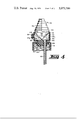
- FIG. 4 is a cross-sectional view of an alternative arrangement showing a finger pump configuration.
- the illustrated sprayer 10 is intended for use in conjunction with a liquid container, preferably a glass or plastic bottle (not shown).
- the sprayer is constructed of a molded body 12, preferably made in two pieces which are bonded together, and contains a plurality of chambers and conduits which are integrally formed within the body 12 for purposes hereinafter to be explained.
- a housing 13, formed as a pistol grip, is bonded to and encloses the body 12.
- the body 12 is connectable to a bottle by means of a threaded cap 14 loosely secured to the base of the body by means of a plug 16.
- the cap 14 rides on the flange 18 of plug 16 which is fixed in the base of the body.
- an inlet bore 20 in the plug and a flexible tube 22 extending into the liquid permit communication between the liquid and a chamber 24 in the housing.
- An outlet bore 26 provides communication between chamber 24 and an adjustable nozzle 28.
- the chamber 24 is rectangular in cross section and is formed with an open front side into which a bellows piston 30 is inserted and secured.
- the bellows piston assembly 30 is shown prior to insertion in FIG. 3. It consists of a bellows 32 formed of a resilient material, preferably plastic or rubber.
- the bellows 32 is rectangular in end view, as seen in FIG. 2.
- Integral tabs 34 and 36 extend from the top and bottom sides of the bellows 32 and have pump inlet and outlet valves formed integrally therein.
- Pump inlet valve 38 in tab 34 comprises an inwardly positioned flap 40 located over inlet port 42.
- Pump outlet valve 44 comprises an outwardly positioned flap 46 located over outlet port 48.
- the tabs 34 and 36 When inserted into chamber 24 the tabs 34 and 36 are squeezed together and forced against the inner, back and side walls of chamber 24. The assembly 30 is then secured in place, dividing the chamber 24 into an inlet reservoir 24 i , and outlet reservoir 24 o and the variable volume 50 between the tabs 34 and 36.
- the method of attachment of the tabs to the body may take many other forms. For example, guides may be provided for sliding the tabs in place, and snap fitting may be used for securing the parts.
- the assembly 30 When installed, the assembly 30 comprises a variable volume chamber 50 having an inlet at port 42 and an outlet at port 48.
- the volume of the chamber 50 is reduced by compressing the bellows 32, the pressure in the chamber 50 causes flap 40 to close in the inlet port 42 and causes flap 46 to open outlet port 48.
- the chamber 50 expands, the operation of the flaps is reversed.
- the bellows and valve arrangement provide a conventional pumping cycle in which fluid is drawn during the intake (or expansion) stroke through tube 22 and bore 20 into the reservoir 24 i and through the intake valve 38 into chamber 50. During the compression stroke the liquid is forced out of chamber 50 into reservoir 24 o and into conduit 26.
- the bellows assembly 30 is compressed by means of a trigger-type lever 52 pivoted at 54 from the housing 13. Intermediate the ends of the trigger is a lug 56 which mates, when actuated, with a cavity 58 formed in the end of bellows 32.
- lever 52 is also used to seal and lock the nozzle 28.
- the end of the body 12 is threaded to receive the nozzle 28.
- the nozzle 28 carries a tab 60 which in turn carries a disc 62.
- the lever 52 is slotted at 64 to permit the passage of the tab therethrough.
- the disc 62 is set at an angle with respect to slot 64 so that the tab cannot be removed without first breaking off the disc.
- the tab 60 serves to permit rotation of the nozzle with respect to the body 12 to adjust the distance of a disc 66 in the center of the nozzle from the end of the outlet conduit 26.
- a projection 68 on the lever serves to seal the outlet port 70 from the nozzle.
- a vent for the bottle to which the spray may be connected is provided by means of a small duct 72 molded in the body 12 and a similar duct 74 in the plug.
- the need for alignment of the duct is obviated by incorporating an annular groove 76 in the plug 16.
- the end 78 of lever 52 serves to seal the duct 72 when the lever is in the locked position.
- the bellows 32 is vertically oriented with respect to the bottle cap 14 by which the pump is attached to a bottle (not shown), and it is finger operated rather than trigger operated.
- the pump shown in FIG. 4 is constructed of a molded hollow rectangular body 80 having an open upper end into which the tab 34 and 36 of the pump 32 extend, and a closed lower end having a circular aperture 82.
- the aperture 82 is closed by means of a plug 84 which is glued in place to the body after being projected through the cap 14.
- a flange 86 on the plug retains the cap 14.
- a port 88 through the plug provides an air vent.
- a tube 90 is frictionally held in a bore 92 extending through the plug 84.
- the body 10 has a spray nozzle 94 threaded into an aperture.
- the bellows 32 when attached within the body 80, divides the hollow interior volume of the body into three sections, an inlet reservoir 96 i , and outlet reservoir 96 o , and the variable volume 98 between the tabs 34 and 36.
- the volume 98 is reduced by compressing the bellows 32, the increased pressure in the chamber 90 causes flap 40 to close inlet port 42 and causes flap 46 to open outlet port 48.
- the chamber 50 expands, the operation of the flaps is reversed.
- the bellows and valve arrangement provides a conventional pumping cycle in which fluid is drawn the intake stroke through the tube 90 and bore 92 into the intake reservoir 96 i , and through the intake valve 38 into chamber 98.
- the liquid is forced out of the chamber 98 and into the reservoir 96 o and into the nozzle 94.
- the bellows may be made circular or have any other cross section other than rectangular.
- the tabs need not be flexed (as disclosed) into a chamber dividing position but may be initially molded into an appropriate configuration.
- the tabs may be a rectangular or circular extension of the bellows and may be closed at the end so that the bellows in combination with the extension provides the entire pump chamber.
Abstract
A pump or spray is comprised of a flexible bellows having a non-collapsible extension in which there are inlet and outlet ports. Flapper valves, integral with the extension, open and close the ports on the compression and expansion strokes of the bellows. The bellows may be finger or trigger operated.
Description
This invention relates to a hand-held liquid, finger-operated pump and trigger sprayer of the type conventionally attachable to bottles containing liquids, such as detergents, soaps, lotions and insecticides. Many devices of this general type are well known in the prior art. One presently used trigger-type of these devices is disclosed in U.S. Pat. No. 3,061,202 issued to Tyler on Oct. 30, 1962. This patent shows a trigger-operated piston pump threaded onto a bottle. After priming, liquid is forced through a nozzle on the compression stroke of the piston and the cylinder refills on the intake stroke. Another presently used sprayer is disclosed in U.S. Pat. No. 3,749,290 issued to Miscallef on July 31, 1973. This patent discloses flexible tubular member which defines a pump chamber, the volume of the chamber being varied by distorting the tube. The present invention operates on the same general principles as the Tyler and Miscallef, but it is far less complex and expensive in that it uses a resilient bellows as the variable volume pump chamber, and all the required valving is molded integrally with an extension from the bellows structure.
Finger-operated pumps are also well known in the art; for example, see Malone, U.S. Pat. No. 3,396,874 and Corsetts, U.S. Pat. No. 323,757. Both of these patents show finger-operated pumps, but neither uses bellows piston having integral valving.
Stengle U.S. Pat. No. 3,409,184 also shows a bellows structure but it fails to teach the use of integral flaps for intake and discharge valving.
Other prior art known to the Applicants includes U.S. Pat. Nos. 788,863, 928,059, 2,112,548, 2,446,085, 2,878,974, 3,128,018, 3,146,920, 3,187,960, 3,237,571, 3,298,573, 3,396,874, 3,572,590 and 3,642,180. None of these is regarded as anticipatory.
The invention is directed to a pump or spray which uses a resilient compressible bellows having integral intake and discharge valves. The pump is housed within a hollow hand grip furnished with a threaded bottle cap for securing the pump to a conventional bottle. The pump may be finger-operated or it may be operated as a spray by means of a trigger initially locked in a pump-disabling position.
FIG. 1 is a cross section of a trigger-operated spray made in accordance with this invention;
FIG. 2 is an end view of FIG. 1;
FIG. 3 is a sectional view of the bellows piston and valves prior to installation; and
FIG. 4 is a cross-sectional view of an alternative arrangement showing a finger pump configuration.
Referring to FIGS. 1-3, the illustrated sprayer 10 is intended for use in conjunction with a liquid container, preferably a glass or plastic bottle (not shown). The sprayer is constructed of a molded body 12, preferably made in two pieces which are bonded together, and contains a plurality of chambers and conduits which are integrally formed within the body 12 for purposes hereinafter to be explained. A housing 13, formed as a pistol grip, is bonded to and encloses the body 12.
The body 12 is connectable to a bottle by means of a threaded cap 14 loosely secured to the base of the body by means of a plug 16. The cap 14 rides on the flange 18 of plug 16 which is fixed in the base of the body.
When threaded onto a bottle, an inlet bore 20 in the plug and a flexible tube 22 extending into the liquid permit communication between the liquid and a chamber 24 in the housing. An outlet bore 26 provides communication between chamber 24 and an adjustable nozzle 28.
The chamber 24 is rectangular in cross section and is formed with an open front side into which a bellows piston 30 is inserted and secured. The bellows piston assembly 30 is shown prior to insertion in FIG. 3. It consists of a bellows 32 formed of a resilient material, preferably plastic or rubber. The bellows 32 is rectangular in end view, as seen in FIG. 2.
When inserted into chamber 24 the tabs 34 and 36 are squeezed together and forced against the inner, back and side walls of chamber 24. The assembly 30 is then secured in place, dividing the chamber 24 into an inlet reservoir 24i, and outlet reservoir 24o and the variable volume 50 between the tabs 34 and 36. The method of attachment of the tabs to the body may take many other forms. For example, guides may be provided for sliding the tabs in place, and snap fitting may be used for securing the parts.
When installed, the assembly 30 comprises a variable volume chamber 50 having an inlet at port 42 and an outlet at port 48. When the volume of the chamber 50 is reduced by compressing the bellows 32, the pressure in the chamber 50 causes flap 40 to close in the inlet port 42 and causes flap 46 to open outlet port 48. When the chamber 50 expands, the operation of the flaps is reversed. Thus, the bellows and valve arrangement provide a conventional pumping cycle in which fluid is drawn during the intake (or expansion) stroke through tube 22 and bore 20 into the reservoir 24i and through the intake valve 38 into chamber 50. During the compression stroke the liquid is forced out of chamber 50 into reservoir 24o and into conduit 26.
The bellows assembly 30 is compressed by means of a trigger-type lever 52 pivoted at 54 from the housing 13. Intermediate the ends of the trigger is a lug 56 which mates, when actuated, with a cavity 58 formed in the end of bellows 32.
In addition to its use as an actuator for the bellows, lever 52 is also used to seal and lock the nozzle 28. As seen in FIG. 1, the end of the body 12 is threaded to receive the nozzle 28. The nozzle 28 carries a tab 60 which in turn carries a disc 62. The lever 52 is slotted at 64 to permit the passage of the tab therethrough. However, the disc 62 is set at an angle with respect to slot 64 so that the tab cannot be removed without first breaking off the disc.
When released, the tab 60 serves to permit rotation of the nozzle with respect to the body 12 to adjust the distance of a disc 66 in the center of the nozzle from the end of the outlet conduit 26.
A projection 68 on the lever serves to seal the outlet port 70 from the nozzle.
A vent for the bottle to which the spray may be connected is provided by means of a small duct 72 molded in the body 12 and a similar duct 74 in the plug. The need for alignment of the duct is obviated by incorporating an annular groove 76 in the plug 16. The end 78 of lever 52 serves to seal the duct 72 when the lever is in the locked position.
In the alternative arrangement shown in FIG. 4, the bellows 32 is vertically oriented with respect to the bottle cap 14 by which the pump is attached to a bottle (not shown), and it is finger operated rather than trigger operated. The pump shown in FIG. 4 is constructed of a molded hollow rectangular body 80 having an open upper end into which the tab 34 and 36 of the pump 32 extend, and a closed lower end having a circular aperture 82. The aperture 82 is closed by means of a plug 84 which is glued in place to the body after being projected through the cap 14. A flange 86 on the plug retains the cap 14.
A port 88 through the plug provides an air vent. A tube 90 is frictionally held in a bore 92 extending through the plug 84. The body 10 has a spray nozzle 94 threaded into an aperture.
The bellows 32, when attached within the body 80, divides the hollow interior volume of the body into three sections, an inlet reservoir 96i, and outlet reservoir 96o, and the variable volume 98 between the tabs 34 and 36. When the volume 98 is reduced by compressing the bellows 32, the increased pressure in the chamber 90 causes flap 40 to close inlet port 42 and causes flap 46 to open outlet port 48. When the chamber 50 expands, the operation of the flaps is reversed. Thus, the bellows and valve arrangement provides a conventional pumping cycle in which fluid is drawn the intake stroke through the tube 90 and bore 92 into the intake reservoir 96i, and through the intake valve 38 into chamber 98. During the compression stroke the liquid is forced out of the chamber 98 and into the reservoir 96o and into the nozzle 94.
While two embodiments of the invention have been illustrated, it will be apparent that the invention is susceptible of a variety of variations. For example, the bellows may be made circular or have any other cross section other than rectangular. In addition, the tabs need not be flexed (as disclosed) into a chamber dividing position but may be initially molded into an appropriate configuration. For example, the tabs may be a rectangular or circular extension of the bellows and may be closed at the end so that the bellows in combination with the extension provides the entire pump chamber.
In addition, while the invention is shown in combination with a threaded attaching device, it is apparent that it may be snap fitted to a container. Further, while the tabs 34 and 36 are preferably made integrally with the bellows, these elements can be separately made and subsequently bonded together.
Claims (15)
1. A fluid pump comprising:
a variable volume, axially collapsible resilient bellows closed at one end and open at the other end;
means for closing said open end, said means including a non-collapsible extension;
an inlet port and an outlet port in said extension; and
a pressure-responsive flexible valve for each of said input and output ports, a respective valve closing said input port and opening said output port in response to a pressure increase within said variable volume, and closing said output port and opening said input port in response to a decrease in pressure within said volume, said valves being integral with said extension.
2. The invention as defined in claim 1 wherein said extension comprises first and second opposed tabs extending from the open end of said bellows, said first tab having said inlet port, said second tab having said outlet port, said flexible valves being integral with said tabs, one of said valves being positioned outside of said volume, other of said valves being located inside of said volume.
3. The invention as defined in claim 2 wherein said extension is integral with said bellows.
4. The invention as defined in claim 3 wherein the distal ends of said extensions are joined.
5. The invention as defined in claim 4 wherein said valves are flaps.
6. A pump comprising:
a body having a chamber therein and an inlet duct and an outlet duct in communication with said chamber, said chamber having an opening through a wall of said body;
a variable volume device including a resilient collapsible bellows having non-collapsible extension, sad extension projecting into said chamber through said opening, and closing of said opening;
an inlet port and an outlet port in said extension;
a first flap integral with said extension for closing said inlet port in response to an increase in pressure within said volume; and
a second flap for closing said output port in response to a decrease in pressure within said volume.
7. The invention as defined in claim 6 wherein said body is connected to a bottle cap.
8. The invention as defined in claim 7 wherein a tube connected to said inlet duct projects through said bottle cap.
9. The invention as defined in claim 8 wherein said bottle cap is provided with vent.
10. The invention as defined in claim 9 wherein said body has an opening by a plug, said plug extending through said cap, said plug having a flange for retaining said cap.
11. The invention as defined in claim 10 wherein said vent comprises an annular groove in said plug, and a hole extending from said groove through said plug
12. The invention as defined in claim 11 wherein said groove communicates with a duct through said body.
13. The invention as defined in claim 12 and a trigger pivoted from said body for axially collapsing said variable volume device.
14. The invention as defined in claim 13 and means for disabling said trigger to prevent movement of said trigger to collape said bellows.
15. The invention as defined in claim 14 wherein said trigger closes said duct when said trigger is disabled.
Priority Applications (1)
| Application Number | Priority Date | Filing Date | Title |
|---|---|---|---|
| US05/617,385 US3973700A (en) | 1975-09-29 | 1975-09-29 | Bellows pump with extension having integral valves |
Applications Claiming Priority (1)
| Application Number | Priority Date | Filing Date | Title |
|---|---|---|---|
| US05/617,385 US3973700A (en) | 1975-09-29 | 1975-09-29 | Bellows pump with extension having integral valves |
Publications (1)
| Publication Number | Publication Date |
|---|---|
| US3973700A true US3973700A (en) | 1976-08-10 |
Family
ID=24473450
Family Applications (1)
| Application Number | Title | Priority Date | Filing Date |
|---|---|---|---|
| US05/617,385 Expired - Lifetime US3973700A (en) | 1975-09-29 | 1975-09-29 | Bellows pump with extension having integral valves |
Country Status (1)
| Country | Link |
|---|---|
| US (1) | US3973700A (en) |
Cited By (50)
| Publication number | Priority date | Publication date | Assignee | Title |
|---|---|---|---|---|
| DE2705071A1 (en) * | 1976-02-09 | 1977-08-11 | Afa Corp | HAND-OPERATED SPRAY DEVICE WITH AUTOMATIC TANK VENTILATION |
| FR2382274A1 (en) * | 1977-03-02 | 1978-09-29 | Tada Tetsuya | TRIGGER TYPE SPRAYER |
| US4201317A (en) * | 1977-07-28 | 1980-05-06 | Aleff Hans P | Finger actuated pump assembly |
| EP0020840A1 (en) * | 1979-05-21 | 1981-01-07 | Yoshino Kogyosho Co., Ltd. | Manual liquid dispensing device for spraying liquid |
| US4336895A (en) * | 1977-07-28 | 1982-06-29 | Aleff Hans P | Finger actuated pump assembly |
| US4345718A (en) * | 1979-04-23 | 1982-08-24 | William Horvath | Manually actuated trigger sprayer |
| US4346821A (en) * | 1978-03-16 | 1982-08-31 | Afa Consolidated Corporation | Child-resistant closures for container mounted spray dispensers |
| US4396132A (en) * | 1981-08-14 | 1983-08-02 | Christensen Kurt K | Apparatus and process for removing and dispensing liquid from a receptacle |
| US4441633A (en) * | 1981-10-26 | 1984-04-10 | Bennett Robert A | Child resistant trigger pump |
| US4640638A (en) * | 1983-03-24 | 1987-02-03 | Sani-Fresh International, Inc. | Cleaning system |
| US4705420A (en) * | 1983-03-24 | 1987-11-10 | Sani-Fresh International, Inc. | Cleaning system having cleaning fluid capsule |
| US4858788A (en) * | 1986-09-30 | 1989-08-22 | Mega Plast Product- U. Verpackungsentwicklung Marketing Gesellschaft Mit Beschrankter Haftung & Co. | Dispensing device for dispersing liquid from a container |
| US4898307A (en) * | 1988-08-25 | 1990-02-06 | Goody Products, Inc. | Spray caps |
| US4971227A (en) * | 1989-06-02 | 1990-11-20 | Calmar, Inc. | Manually actuated dispensing pump sprayer having a removable nozzle locking element |
| US5040701A (en) * | 1989-06-02 | 1991-08-20 | Calmar Inc. | Manually actuated dispensing pump sprayer having a removable nozzle locking element |
| US5114052A (en) * | 1988-08-25 | 1992-05-19 | Goody Products, Inc. | Manually actuated trigger sprayer |
| WO1993016955A1 (en) * | 1992-02-24 | 1993-09-02 | Afa Products, Inc. | Flap valve assembly for trigger sprayer |
| US5297701A (en) * | 1992-02-24 | 1994-03-29 | Afa Products, Inc. | All plastic trigger sprayer |
| US5303867A (en) * | 1993-06-24 | 1994-04-19 | The Procter & Gamble Company | Trigger operated fluid dispensing device |
| EP0598237A2 (en) * | 1992-10-21 | 1994-05-25 | Contico International, Incorporated | Trigger sprayer |
| US5332128A (en) * | 1992-02-24 | 1994-07-26 | Afa Products, Inc. | Flap valve assembly for trigger sprayer |
| WO1995000253A1 (en) * | 1993-06-24 | 1995-01-05 | The Procter & Gamble Company | Collapsible pump chamber having predetermined collapsing pattern |
| US5439178A (en) * | 1993-06-24 | 1995-08-08 | The Procter & Gamble Company | Pump device including multiple function collapsible pump chamber |
| US5462208A (en) * | 1994-08-01 | 1995-10-31 | The Procter & Gamble Company | Two-phase dispensing systems utilizing bellows pumps |
| US5476195A (en) * | 1994-10-06 | 1995-12-19 | Procter & Gamble Company | Pump device with collapsible pump chamber and including dunnage means |
| US5518147A (en) * | 1994-03-01 | 1996-05-21 | The Procter & Gamble Company | Collapsible pump chamber having predetermined collapsing pattern |
| US5561901A (en) * | 1994-10-06 | 1996-10-08 | The Procter & Gamble Company | Assembly process including severing part of integral collapsible pump chamber |
| US5603434A (en) * | 1993-12-11 | 1997-02-18 | Owens-Illinois Closure Inc. | Trigger sprayer |
| US5664703A (en) * | 1994-02-28 | 1997-09-09 | The Procter & Gamble Company | Pump device with collapsible pump chamber having supply container venting system and integral shipping seal |
| US5687880A (en) * | 1996-04-24 | 1997-11-18 | Afa Products, Inc. | Child lock nozzle cap assembly |
| US5716008A (en) * | 1996-03-04 | 1998-02-10 | Nottingham-Spirk Design Associates, Inc. | Trigger sprayer |
| US5762236A (en) * | 1996-01-16 | 1998-06-09 | Contico International, Inc. | Trigger mechanism for trigger sprayer |
| US5894960A (en) * | 1997-04-29 | 1999-04-20 | 3D Design And Engineering | Pump mechanism for mechanical dispensers |
| US6168050B1 (en) * | 1998-04-21 | 2001-01-02 | Guala Dispensing S.P.A. | Hand-operated pump with a trigger, for dispensing liquids |
| US6244469B1 (en) | 1998-01-14 | 2001-06-12 | Michael G. Knickerbocker | Child resistant trigger for dispenser |
| US6244473B1 (en) * | 1999-12-17 | 2001-06-12 | Owens-Illinois Closure Inc. | Pump dispenser having vent valve |
| FR2804728A1 (en) | 2000-02-09 | 2001-08-10 | Oreal | PUMP, AND PACKAGING ASSEMBLY PROVIDED WITH SUCH A PUMP |
| US6527202B1 (en) * | 2002-04-29 | 2003-03-04 | Living Fountain Plastic Industrial Co., Ltd. | Compression structure of a spray gun |
| US20040211792A1 (en) * | 2003-04-28 | 2004-10-28 | Nottingham-Spirk Design Associates, Inc., An Ohio Corporation | Pump drive unit for battery operated fluid dispensers |
| WO2006027102A1 (en) * | 2004-09-09 | 2006-03-16 | Ing. Erich Pfeiffer Gmbh | Dosing device with capillary air supply |
| US20060113329A1 (en) * | 2004-11-29 | 2006-06-01 | Seaquisperfect Dispensing Foreign, Inc. | Dispenser with lock |
| US7249692B2 (en) | 2004-11-29 | 2007-07-31 | Seaquistperfect Dispensing Foreign, Inc. | Dispenser with lock |
| US20080006717A1 (en) * | 2004-10-27 | 2008-01-10 | Eric Junkel | Portable misting device with drinking spout and fan assist |
| US7806301B1 (en) * | 2004-05-19 | 2010-10-05 | Joseph S Kanfer | Dome pump |
| US20120237377A1 (en) * | 2011-03-16 | 2012-09-20 | Hübner GmbH | Pump device for a container for liquid, pasty or foamable cleansing and skin care preparations |
| FR3005459A1 (en) * | 2013-05-13 | 2014-11-14 | Gb Dev | DEVICE FOR DISPENSING A FLUID AND METHOD FOR MANUFACTURING SUCH A DEVICE |
| US20150128938A1 (en) * | 2012-05-24 | 2015-05-14 | Aptar France Sas | Device for distributing a fluid product |
| US20150238709A1 (en) * | 2014-02-21 | 2015-08-27 | Neogen Corporation | Fluid Atomizer, Nozzle Assembly and Methods for Assembling and Utilizing the Same |
| US20150273486A1 (en) * | 2012-10-31 | 2015-10-01 | Yoshino Kogyosho Co., Ltd. | Ejection head and container provided with the same |
| US20220055052A1 (en) * | 2019-02-08 | 2022-02-24 | Kao Corporation | Dispenser |
Citations (2)
| Publication number | Priority date | Publication date | Assignee | Title |
|---|---|---|---|---|
| US1647219A (en) * | 1922-10-16 | 1927-11-01 | Fulton Sylphon Co | Receptacle for discharging fluids |
| US3160329A (en) * | 1963-02-26 | 1964-12-08 | Radic Frank | Dispensing device |
-
1975
- 1975-09-29 US US05/617,385 patent/US3973700A/en not_active Expired - Lifetime
Patent Citations (2)
| Publication number | Priority date | Publication date | Assignee | Title |
|---|---|---|---|---|
| US1647219A (en) * | 1922-10-16 | 1927-11-01 | Fulton Sylphon Co | Receptacle for discharging fluids |
| US3160329A (en) * | 1963-02-26 | 1964-12-08 | Radic Frank | Dispensing device |
Cited By (72)
| Publication number | Priority date | Publication date | Assignee | Title |
|---|---|---|---|---|
| DE2705071A1 (en) * | 1976-02-09 | 1977-08-11 | Afa Corp | HAND-OPERATED SPRAY DEVICE WITH AUTOMATIC TANK VENTILATION |
| FR2382274A1 (en) * | 1977-03-02 | 1978-09-29 | Tada Tetsuya | TRIGGER TYPE SPRAYER |
| US4201317A (en) * | 1977-07-28 | 1980-05-06 | Aleff Hans P | Finger actuated pump assembly |
| US4336895A (en) * | 1977-07-28 | 1982-06-29 | Aleff Hans P | Finger actuated pump assembly |
| US4346821A (en) * | 1978-03-16 | 1982-08-31 | Afa Consolidated Corporation | Child-resistant closures for container mounted spray dispensers |
| US4345718A (en) * | 1979-04-23 | 1982-08-24 | William Horvath | Manually actuated trigger sprayer |
| EP0020840A1 (en) * | 1979-05-21 | 1981-01-07 | Yoshino Kogyosho Co., Ltd. | Manual liquid dispensing device for spraying liquid |
| US4396132A (en) * | 1981-08-14 | 1983-08-02 | Christensen Kurt K | Apparatus and process for removing and dispensing liquid from a receptacle |
| US4441633A (en) * | 1981-10-26 | 1984-04-10 | Bennett Robert A | Child resistant trigger pump |
| US4640638A (en) * | 1983-03-24 | 1987-02-03 | Sani-Fresh International, Inc. | Cleaning system |
| US4705420A (en) * | 1983-03-24 | 1987-11-10 | Sani-Fresh International, Inc. | Cleaning system having cleaning fluid capsule |
| US4858788A (en) * | 1986-09-30 | 1989-08-22 | Mega Plast Product- U. Verpackungsentwicklung Marketing Gesellschaft Mit Beschrankter Haftung & Co. | Dispensing device for dispersing liquid from a container |
| US4898307A (en) * | 1988-08-25 | 1990-02-06 | Goody Products, Inc. | Spray caps |
| US5114052A (en) * | 1988-08-25 | 1992-05-19 | Goody Products, Inc. | Manually actuated trigger sprayer |
| EP0401965A2 (en) * | 1989-06-02 | 1990-12-12 | Calmar Inc. | Manually actuated dispensing pump sprayer having a removable nozzle locking element |
| US4971227A (en) * | 1989-06-02 | 1990-11-20 | Calmar, Inc. | Manually actuated dispensing pump sprayer having a removable nozzle locking element |
| EP0401965A3 (en) * | 1989-06-02 | 1991-11-21 | Calmar Inc. | Manually actuated dispensing pump sprayer having a removable nozzle locking element |
| US5040701A (en) * | 1989-06-02 | 1991-08-20 | Calmar Inc. | Manually actuated dispensing pump sprayer having a removable nozzle locking element |
| GB2278891A (en) * | 1992-02-24 | 1994-12-14 | Afa Products Inc | Flap valve assembly for trigger sprayer |
| US5297701A (en) * | 1992-02-24 | 1994-03-29 | Afa Products, Inc. | All plastic trigger sprayer |
| WO1993016955A1 (en) * | 1992-02-24 | 1993-09-02 | Afa Products, Inc. | Flap valve assembly for trigger sprayer |
| US5332128A (en) * | 1992-02-24 | 1994-07-26 | Afa Products, Inc. | Flap valve assembly for trigger sprayer |
| AU666183B2 (en) * | 1992-02-24 | 1996-02-01 | Afa Products, Inc. | Flap valve assembly for trigger sprayer |
| GB2278891B (en) * | 1992-02-24 | 1995-07-12 | Afa Products Inc | Trigger operated dispensing device |
| EP0598237A2 (en) * | 1992-10-21 | 1994-05-25 | Contico International, Incorporated | Trigger sprayer |
| EP0598237A3 (en) * | 1992-10-21 | 1994-09-21 | Contico Int Inc | Trigger sprayer. |
| EP0742050A3 (en) * | 1992-10-21 | 1997-05-02 | Contico Int Inc | Trigger sprayer |
| EP0742050A2 (en) * | 1992-10-21 | 1996-11-13 | Contico International, Incorporated | Trigger sprayer |
| AU678463B2 (en) * | 1993-06-24 | 1997-05-29 | Procter & Gamble Company, The | Collapsible pump chamber having predetermined collapsing pattern |
| US5303867A (en) * | 1993-06-24 | 1994-04-19 | The Procter & Gamble Company | Trigger operated fluid dispensing device |
| CN1069232C (en) * | 1993-06-24 | 2001-08-08 | 普罗格特-甘布尔公司 | Collapsible pump chamber having predetermined collapsing pattern |
| US5439178A (en) * | 1993-06-24 | 1995-08-08 | The Procter & Gamble Company | Pump device including multiple function collapsible pump chamber |
| WO1995000253A1 (en) * | 1993-06-24 | 1995-01-05 | The Procter & Gamble Company | Collapsible pump chamber having predetermined collapsing pattern |
| US5738251A (en) * | 1993-12-11 | 1998-04-14 | Owens-Illinois Closure Inc. | Trigger sprayer |
| US5603434A (en) * | 1993-12-11 | 1997-02-18 | Owens-Illinois Closure Inc. | Trigger sprayer |
| US5664703A (en) * | 1994-02-28 | 1997-09-09 | The Procter & Gamble Company | Pump device with collapsible pump chamber having supply container venting system and integral shipping seal |
| US5518147A (en) * | 1994-03-01 | 1996-05-21 | The Procter & Gamble Company | Collapsible pump chamber having predetermined collapsing pattern |
| AU705669B2 (en) * | 1994-08-01 | 1999-05-27 | Procter & Gamble Company, The | Improved two-phase dispensing systems utilizing bellows pumps |
| WO1996004078A1 (en) * | 1994-08-01 | 1996-02-15 | The Procter & Gamble Company | Improved two-phase dispensing systems utilizing bellows pumps |
| US5462208A (en) * | 1994-08-01 | 1995-10-31 | The Procter & Gamble Company | Two-phase dispensing systems utilizing bellows pumps |
| US5561901A (en) * | 1994-10-06 | 1996-10-08 | The Procter & Gamble Company | Assembly process including severing part of integral collapsible pump chamber |
| US5476195A (en) * | 1994-10-06 | 1995-12-19 | Procter & Gamble Company | Pump device with collapsible pump chamber and including dunnage means |
| US5762236A (en) * | 1996-01-16 | 1998-06-09 | Contico International, Inc. | Trigger mechanism for trigger sprayer |
| US5716008A (en) * | 1996-03-04 | 1998-02-10 | Nottingham-Spirk Design Associates, Inc. | Trigger sprayer |
| US5687880A (en) * | 1996-04-24 | 1997-11-18 | Afa Products, Inc. | Child lock nozzle cap assembly |
| US5894960A (en) * | 1997-04-29 | 1999-04-20 | 3D Design And Engineering | Pump mechanism for mechanical dispensers |
| US6244469B1 (en) | 1998-01-14 | 2001-06-12 | Michael G. Knickerbocker | Child resistant trigger for dispenser |
| US6168050B1 (en) * | 1998-04-21 | 2001-01-02 | Guala Dispensing S.P.A. | Hand-operated pump with a trigger, for dispensing liquids |
| US6425501B1 (en) * | 1999-12-17 | 2002-07-30 | Owens-Llinois Closure Inc. | Pump dispenser having vent valve |
| US6244473B1 (en) * | 1999-12-17 | 2001-06-12 | Owens-Illinois Closure Inc. | Pump dispenser having vent valve |
| FR2804728A1 (en) | 2000-02-09 | 2001-08-10 | Oreal | PUMP, AND PACKAGING ASSEMBLY PROVIDED WITH SUCH A PUMP |
| US6547106B2 (en) | 2000-02-09 | 2003-04-15 | L'oreal S.A. | Pump for dispensing a product |
| US6527202B1 (en) * | 2002-04-29 | 2003-03-04 | Living Fountain Plastic Industrial Co., Ltd. | Compression structure of a spray gun |
| US20040211792A1 (en) * | 2003-04-28 | 2004-10-28 | Nottingham-Spirk Design Associates, Inc., An Ohio Corporation | Pump drive unit for battery operated fluid dispensers |
| US7318539B2 (en) | 2003-04-28 | 2008-01-15 | Power Sprayer Llc | Pump drive unit for battery operated fluid dispensers |
| US7806301B1 (en) * | 2004-05-19 | 2010-10-05 | Joseph S Kanfer | Dome pump |
| JP2008512312A (en) * | 2004-09-09 | 2008-04-24 | インジ エリッヒ プファイファ ゲーエムベーハ | Metering equipment |
| WO2006027102A1 (en) * | 2004-09-09 | 2006-03-16 | Ing. Erich Pfeiffer Gmbh | Dosing device with capillary air supply |
| US20070284393A1 (en) * | 2004-09-09 | 2007-12-13 | Stefan Ritsche | Dosing Device with Capillary Air Supply |
| US20080006717A1 (en) * | 2004-10-27 | 2008-01-10 | Eric Junkel | Portable misting device with drinking spout and fan assist |
| US7249692B2 (en) | 2004-11-29 | 2007-07-31 | Seaquistperfect Dispensing Foreign, Inc. | Dispenser with lock |
| US20060113329A1 (en) * | 2004-11-29 | 2006-06-01 | Seaquisperfect Dispensing Foreign, Inc. | Dispenser with lock |
| US20120237377A1 (en) * | 2011-03-16 | 2012-09-20 | Hübner GmbH | Pump device for a container for liquid, pasty or foamable cleansing and skin care preparations |
| EP2499950A3 (en) * | 2011-03-16 | 2017-06-28 | Hübner GmbH | Pump device for a container for liquid, paste or foamable skin cleaning and care preparations |
| US20150128938A1 (en) * | 2012-05-24 | 2015-05-14 | Aptar France Sas | Device for distributing a fluid product |
| US10080852B2 (en) * | 2012-05-24 | 2018-09-25 | Aptar France Sas | Fluid dispenser device with bellows |
| US20150273486A1 (en) * | 2012-10-31 | 2015-10-01 | Yoshino Kogyosho Co., Ltd. | Ejection head and container provided with the same |
| US9827577B2 (en) * | 2012-10-31 | 2017-11-28 | Yoshino Kogyosho Co., Ltd. | Ejection head and container provided with the same |
| FR3005459A1 (en) * | 2013-05-13 | 2014-11-14 | Gb Dev | DEVICE FOR DISPENSING A FLUID AND METHOD FOR MANUFACTURING SUCH A DEVICE |
| US20150238709A1 (en) * | 2014-02-21 | 2015-08-27 | Neogen Corporation | Fluid Atomizer, Nozzle Assembly and Methods for Assembling and Utilizing the Same |
| US9821126B2 (en) * | 2014-02-21 | 2017-11-21 | Neogen Corporation | Fluid atomizer, nozzle assembly and methods for assembling and utilizing the same |
| US20220055052A1 (en) * | 2019-02-08 | 2022-02-24 | Kao Corporation | Dispenser |
Similar Documents
| Publication | Publication Date | Title |
|---|---|---|
| US3973700A (en) | Bellows pump with extension having integral valves | |
| US4489861A (en) | Manual liquid dispensing device | |
| US4191313A (en) | Trigger operated dispenser with means for obtaining continuous or intermittent discharge | |
| US5551636A (en) | Low cost trigger sprayer having elastomeric pump with internal guide means | |
| US4640444A (en) | Pump dispenser with slidable trigger | |
| US4249681A (en) | Leak-proof sprayer | |
| US4050613A (en) | Manual actuated dispensing pump | |
| US4618077A (en) | Liquid dispensing pump | |
| US5553752A (en) | Spring for trigger sprayer | |
| US7637396B2 (en) | Trigger sprayer piston rod with integral spring and ball and socket piston connection | |
| US5184755A (en) | Toy water gun utilizing an air pressure pump | |
| US5772078A (en) | Combined turret and closure seal | |
| US8104646B2 (en) | Trigger sprayer having a reduced number of parts and a double tubular valve member | |
| US5979712A (en) | Upright/inverted sprayer | |
| US5353969A (en) | Invertible pump sprayer having spiral vent path | |
| JP2000176332A (en) | Trigger acting pump type sprayer | |
| JP4327276B2 (en) | Medium dispenser | |
| US20070215648A1 (en) | Trigger Sprayer Piston Rod With Integral Spring and Pivoting Piston Connection | |
| USRE33235E (en) | Liquid dispensing pump | |
| US4182465A (en) | Manually operated pump using hollow flexible member as pumping chamber | |
| AU2004201921B2 (en) | Low cost, in-line trigger operated pump sprayer | |
| US5575407A (en) | Low cost trigger sprayer having container with integral saddle | |
| CA1165288A (en) | Trigger actuated pump | |
| GB1453014A (en) | Dispensing unit for liquid | |
| US5568886A (en) | Combined turret and closure seal |