US3842735A - Lithographic printing apparatus and wash-up device - Google Patents
Lithographic printing apparatus and wash-up device Download PDFInfo
- Publication number
- US3842735A US3842735A US00317723A US31772372A US3842735A US 3842735 A US3842735 A US 3842735A US 00317723 A US00317723 A US 00317723A US 31772372 A US31772372 A US 31772372A US 3842735 A US3842735 A US 3842735A
- Authority
- US
- United States
- Prior art keywords
- dampener
- ink
- roll means
- form roll
- roller
- Prior art date
- Legal status (The legal status is an assumption and is not a legal conclusion. Google has not performed a legal analysis and makes no representation as to the accuracy of the status listed.)
- Expired - Lifetime
Links
- 238000005096 rolling process Methods 0.000 claims description 10
- 230000033001 locomotion Effects 0.000 claims description 8
- 230000000694 effects Effects 0.000 claims description 2
- 230000002093 peripheral effect Effects 0.000 claims description 2
- 238000004140 cleaning Methods 0.000 abstract description 6
- XLYOFNOQVPJJNP-UHFFFAOYSA-N water Substances O XLYOFNOQVPJJNP-UHFFFAOYSA-N 0.000 description 10
- 230000005540 biological transmission Effects 0.000 description 3
- 230000002745 absorbent Effects 0.000 description 2
- 239000002250 absorbent Substances 0.000 description 2
- VYZAMTAEIAYCRO-UHFFFAOYSA-N Chromium Chemical compound [Cr] VYZAMTAEIAYCRO-UHFFFAOYSA-N 0.000 description 1
- RYGMFSIKBFXOCR-UHFFFAOYSA-N Copper Chemical compound [Cu] RYGMFSIKBFXOCR-UHFFFAOYSA-N 0.000 description 1
- 229910052802 copper Inorganic materials 0.000 description 1
- 239000010949 copper Substances 0.000 description 1
- 230000008878 coupling Effects 0.000 description 1
- 238000010168 coupling process Methods 0.000 description 1
- 238000005859 coupling reaction Methods 0.000 description 1
- 230000008020 evaporation Effects 0.000 description 1
- 238000001704 evaporation Methods 0.000 description 1
- 239000004744 fabric Substances 0.000 description 1
- 239000012530 fluid Substances 0.000 description 1
- 238000000034 method Methods 0.000 description 1
- 239000000203 mixture Substances 0.000 description 1
- 239000010409 thin film Substances 0.000 description 1
Images

Classifications
-
- B—PERFORMING OPERATIONS; TRANSPORTING
- B41—PRINTING; LINING MACHINES; TYPEWRITERS; STAMPS
- B41F—PRINTING MACHINES OR PRESSES
- B41F35/00—Cleaning arrangements or devices
- B41F35/002—Cleaning arrangements or devices for dampening rollers
-
- B—PERFORMING OPERATIONS; TRANSPORTING
- B41—PRINTING; LINING MACHINES; TYPEWRITERS; STAMPS
- B41F—PRINTING MACHINES OR PRESSES
- B41F35/00—Cleaning arrangements or devices
- B41F35/04—Cleaning arrangements or devices for inking rollers
-
- B—PERFORMING OPERATIONS; TRANSPORTING
- B41—PRINTING; LINING MACHINES; TYPEWRITERS; STAMPS
- B41F—PRINTING MACHINES OR PRESSES
- B41F7/00—Rotary lithographic machines
- B41F7/20—Details
- B41F7/24—Damping devices
- B41F7/36—Inking-rollers serving also to apply ink repellants
Definitions
- One main aspect of this invention relates primarily to lithographic dampeners of .the bareback form roller type which carry both ink and dampening solution or water in their normal printing operation.
- Such is disclosed in copending Sylvester et al, application, Ser. No. 285,137. This eliminates a hand wash-up of the bareback dampener roller separately from the inker, thus reducing clean-up time between jobs or at the end of a shift.
- bareback dampener form rollers require, in order to achieve high quality printing, that no relative motion be permitted between the surface of the printing plate and the. dampener form roller. This has been accomplished in the past by various techniques, such as driving the dampener form roller through a slipping clutch or various types of couplings. Such a drive presents problems in that the size of the dampener form roller is occasionally ground for truing the surface, as is known.
- a second aspect of the present invention involves the provision of a frictional drive for the dampener form roller when it is in its non-printing position, whereby it runs at the surface speed of the printing plate at the time it engages the plate when moved from nonprinting to printing position.
- a bareback form roller is not essential to this aspect when used independently of the clean-up feature of the invention.
- a bareback dampener form roller receives water from a hydrophilic dampener roller and supplies it to a lithographic printing plate.
- the dampener form roller is resilient and is capable of carrying ink as well as water.
- a rider roller engages the bareback dampener form roller in its printing position, and preferably has an oscillating motion to laterally distribute any ink or water pattern which may form on the dampener roller.
- the rider roller and dampener form roller move in unison but are maintained in contact. In such non-printing position, both are out of contact with all other rollers of the dampener and inker.
- the rider roller is positively driven and drives the surface of the dampener form roller when in non-printing position, so that subsequent return of the dampener form roller to printing position provides that it travel at the surface speed of the plate at the time it rolls in contact with the plate.
- an ink form roller closely adjacent the rider roller has three positions of operation: a printing position, a first throw-off position where it is out of contact with the plate but remains in contact with its ink supply roller, and a second throw-off position similar to the first, but where it further contacts the rider roller of the dampener when the rider roller and dampener form rollerare in their non-printing positions.
- the rider roller and dampener form roller are in fluid-transmitting engagement with the inker, thereby enabling wash-up of BRIEF DESCRIPTION OF THE DRAWINGS
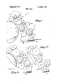
- FIG. 1 is a simplified side elevational view of a dampener and a portion of an inker according to the invention, parts being omitted for clarity;
- FIG. 2 is a view similar to FIG. 1 wherein-all of the rollers of the inker and dampener are'in their throw-off or non-printing positions;
- FIG. 3 is a-view similar to FIG. 2 wherein the various rollers are in their wash-up" positions;
- FIG. 4 is a view illustrating the ink'form roller in its printing and first throw-off positions
- FIG. 5 is a view similar to FIG. 4 wherein the ink form roller has been moved to a second throw-off position for wash-up of both the inker and inked dampener rolls.
- a conventional lithographic printing press includes a plate cylinder 10, a dampener 11, and an inker 12, only a few rollers of which are shown.
- the plate cylinder 10 is provided with a pair of conventional clamps 13 which are located in a gap in the cylinder 10. The clamps 13 grip the leading and trailing edges of a lithographic printing plate 14 to secure it to the surface of the cylinder 10.
- the plate cylinder 10 rotates counterclock wise.
- the plate 14 first receives a thin film of fountain solution or water 15 by means of rollers of the dampener 11, and is then contacted by rollers of the inker 12 in conventional fashion.
- the inker 12 may be of any design, but customarily includes an ink distributing roller 16 which normally vibrates or oscillates axially, and resilient ink form rollers 17 and 18 which receive ink from the distributing roller 16 and transmit it to the plate 14.
- the form rollers 17 and 18 are in their full-line position when printing and are moved to their dotted-line positions during interruption of printing, such as that occasioned by a press stoppage or a trip to slow speed.
- Actuation of the rollers'l7 and 18 between their printing and non-printing positions is conventionally done by rotation of a means such as throw-off shaft 19.
- the shaft 19 has a pair of flats thereon at each end of the inker. Abutments supported by arms for the form rolls l7 and 18 engage the flats during printing.
- the support arms for the form rollers, as well as the support for a number of rollers for the dampener, to be described subsequently, have been simply shown as lines indicating the interconnection of the rollers.
- Rollers 17 and 18 are spring-urged toward the cylinder 10, as is conventional.
- Usual stop means are provided to limit the inward movement of the rollers l7 and 18 to prevent their dropping in the gap in the cylinder 10 when it rotates adjacent the form rollers.
- the shaft 19, when in the position shown, enables the form rollers 17 and 18 to be placed in contact with the plate 14.
- Usual adjustment means is provided for setting the pressure or stripe between each form roller and the plate. When shaft 19 is rotated so that the round portions thereof urge the supporting arms for the rollers 17 and 18 outwardly, the rollers will move to their dotted-line positions. As shown, the dotted-line positionof the roller 17 is the second or intermediate one of three positions for that roller.
- the dampener 11 includes a pan 20 for the fountain solution 15, a metering pan roll 21 which has its lower surface immersed in the solution 15, a slip roll 22 generally vertically above the pan roll 21, an intermediate vibrator roller 23 contacted by the slip roll 22, a resilient' bareback form roller 24 contacting the vibratory roll 23 and the plate 14 when in printing position, and
- rollers 21 and 22 break contact with the roller 23.
- the' usual pressure adjustments are provided not only between the rollers 21 and 22, but also between all other rollers of the system for arranging the rollers in the best mode desired for their effective and proper operation.
- Gears are provided at oneend of each of rollers 21 and 22 so that their surfaces may rotate in the same direction at a metering nip 26 therebetween.
- One of the gears of the rollers 21 and 22 is driven in conventional fashion by a motor (not shown) which is independent of the press drive, whereby rollers 21 and 22 may be driven, although the remainder of the press may be idle at the time.
- roller 23 is a fixed-axis hydrophilic roller. Its surface may be highly polished chrome to avoid receiving ink thereon when the surface has first been dampened. This prevents rearward transmission of ink in the dampener toward the rollers 22 and 21. Tinting of the fountain solution 15 is thus effectively avoided or minimized, and rollers 21, 22 and 23 are kept clean in normal operation.
- the resilient form roller 24 is preferably a bareback roller, i.e., one having no absorbent covering thereon.
- bareback roller it has a normal affinity for ink during press operation, although its primary purpose is to carry water supplied by the intermediate roller 23 to the surface of the plate 14.
- the roller 24 may be provided with any of the various types of paper or cloth absorbent covers. Even in such a case, however, the covers are known to get dirty and thus have the capability of transmitting ink to the roller 23 unless it is made hydrophilic to prevent such transmission.
- the rider roller rides atop the roller 24 during printing, and is preferably made to oscillate endwise to break up any pattern of ink or water on the surface of the roller 24.
- the roller 25 has a driven gear 27 at one end thereof which intermeshes with a driving gear 28. This provides a drive to the axis of the roll 25 at all times when the driving gear 28 is rotating.
- gear 28 is driven from a plate cylinder gear 29 which drives through a pair of idler gears 30 and 31. In this fashion, any time the press is operating and the plate cylinder 10 is rotating, the gear 28 and thus the rider roll 25 rotates.
- the dampener form roller 24 is movable from a solid-line printing position to a dotted-line non-printing position in which it is out of contact with the plate 14 and the hydrophilic roller 23.
- the dampener form roller 24 is normally moved to its non-printing position at times when the press is not printing and the shut-down period is to last for more than a few minutes.
- the rider roller 25 is maintained in contact with the form roller 24 in both the printing and non-printing positions of the form roller 24.
- the rider roller 25 is moved to its dotted-line position, shown in FIG.
- rollers 24 and 25 are moved into and out of printing position, preferably in unison.
- Gears 27 and 28 are maintained in mesh in both positions of rollers 25, the roller being swingable about the axis of the gear 28 by means of arms supporting the ends of the roller 25.
- roller 24 may vary according to the number of times it has been ground for resurfacing, there is no longer a problem of matching the surface speed of the form roller with the plate.
- rolls 24 and 25 are preferably moved in unison while being maintained in contact so that the roll 24 first engages roll 23 and then the surface of the plate 14. This movement is normally rapid.
- evaporation of water occurred at rollers 24 and 25 while in the throw-off position, it is possible that a stripe of dry ink from'the roller 24 will be deposited on the surface of the printing plate 14.
- timi ing means may be provided to assure that the throw-on of rolls 24 and 25 is made to occur so that roll 24 will move to its final printing location when the cylinder gap comes into position, thereby allowing the roller 23 to deposit sufficient dampening solution onto the surface of the now-dried roller 24 to provide water to the plate as the lead edge comes around when the roller 24 crosses the gap. This would assure that any shut-down period of the press, during which there was time for water to evaporate from the form roller 24, is avoided as a problem.
- roller 24 be provided with a surface drive at all times, except when the press isactually stopped.
- roller 24 is driven solely by rider roller 25.
- Rider roller 25 is normally metallic and provided with a surface such as copper, which is capable of carrying ink. With both rollers 24 and 25 carrying ink, the coefficient of friction between the two for driving purposes form roller 24 has no bearing on the final print results,
- the ink form roller 17 is moved from the position shown in FIG. 2 where it contacts only the distributor roller 16 to the position of FIG. 3 where it additionally contacts the rider roller 25.
- the rolls of the inker are placed in fluidtransmitting engagement with the rolls 25 and 24 of the dampener, both of which carry ink during normal printing.
- the press can be operated at high speed with the rolls in the condition of FIG. 3, at which time cleaning solution is squirted onto the inker rollers and runs over the contacting surfaces.
- a conventional wash-up device is provided at a convenient location to scrape any dissolved ink from the inker. After the bulk of the ink has been removed from the system, a final touch may be applied by hand-wiping, as is customary.
- the utilization of the ink form roller 17 to connect with those rollers of the dampener 11 which normally carry ink provides an additional feature to a system in which the rider roller 25 and dampener form roller 24 are maintained in contact during the throw-off position.
- the rider roller 25 also has eccentrics at its ends to enable it to be moved out of contact from the dampener form roller 24 to prevent flats from forming on the dampener form roller during long periods of shutdown, such as overnight.
- FIGS. 4 and 5 illustrate one manner in which the ink form roller 17 can be moved between its three positions.
- the rolls 24 and 25 are illustrated in their non-printing positions.
- roller 17 is moved from its full-line or printing position to its dotted-line position by the shaft 19 as discussed in connection with FIG. 1.
- a pair of links-32 move to their dotted-line position, compressing springs 33 which surround rods 34.
- the heads 35 of the rods 34 are pivoted in the arms 32 and the rods 34 pass through noddle pins 36 pivotally mounted in the ends of links 37.
- Links 37 are urged toward the roller 17 by tension springs 38 connected to pins 39 in a frame member 40 of the inker.
- the mechanism just described is duplicated at both ends of the press and is interconnected by a cross-shaft 41 journaled in the links 37.
- the rods 34 have locknuts 42 threaded at the outer ends thereof. These locknuts may provide the innermost pressure setting of the roller 17 against the plate 14 when in the full-line position of FIG. 4.
- the springs 38 have sufficient force to maintain the links 37 in their leftward position when the roll 17 is moved to its dotted-line position of FIG. 4. At such time, springs 33 are compressed, and the nuts 42 will lift slightly from their abutting engagement with the noddle pins 36.
- a lever 43 When it is desired to move the form roller 17 to its wash-up position where it contacts the rider roller 25, a lever 43 is turned clockwise to operate a cam member 44 pivotally supported on the cross-shaft 41.
- the cam member 44 includes a roller 45 which rides up a verti-- cal surface of the frame member 40 during operation to the position shown in FIG. 5. It should be understood that cam member 44 and roller 45, as well as other parts for moving roller 17 to its dot-dash position, are duplicated at both ends of the inker 12.
- por tions of the cam members 44 will engage horizontal surfaces of the frame member 40, acting to stop further pivotal movement of the cam members 44. Engagement of the rollers 45 with the vertical surfaces of the member 40 moves the links 37 counterclockwise, and extends springs 38.
- the initial movement of the links 37 causes the noddle pins 36 to engage the nuts 42, after which time a positive pull in a rightward direction is placed on the rods 34, thus urging the ink form roller 17 further in a counterclockwise direction.
- the roller 17 engages the rider roller 25, it becomes capable of transmitting ink or a mixture of ink and wash-up solution to the rollers 24 and 25.
- a return of the lever 43 to its vertical position as shown in FIG. 4 will restore the parts to the positions shown in FIG. 4, and, of course, the form roller 17 reassumes its dotted-line position at that time.
- eccentrics 46 surrounding the cross-shaft 41 and supported in the links 37.
- the setting of the eccentrics 46 would normally be accomplished after the nuts on the rods 34 are adjusted to their final position for striping the ink form roller 17 to the plate 14.
- a lithographic printing press comprising plate cylinder means for carrying a lithographic printing plate during a printing operation, inker means for transmitting irik from a source of ink to the lithographic printing plate during a printing operation, said inker means including an ink distributing roll and ink form roll means for receiving ink from said ink distributing roll and applying ink to the lithographic printing plate, and dampener means for transmitting dampening solution from a source of dampening solution to the lithographic printing plate during a printing operation, said dampener means including dampener form roll means for applying dampening solution to the lithographic printing plate during a printing operation, distributing roll means for transmitting dampening solution along a flow path from the source of dampening solution to said dampener form roll means and for distributing the dampening solution on the surface of said dampener form roll means, and dampener throw-off means for moving said dampener form roll means between a printing position in which said dampener form roll means is disposed in rolling engagement with the
- a driven gear at one end of said rider roller, a driving gear in driving engagement with said driven gear, said driven gear and said rider roller being supported about the axis of said driving gear to accommodate pivotal movement of said rider roller and driven gear about the axis of the driving gear when said dampener form roll means is moved to its thrown-off position
Abstract
Lithographic dampener has a hydrophilic roller for supplying dampening solution to a resilient dampener form roller capable of carrying ink and dampening solution. The dampener form roller is driven primarily by surface contact from the printing plate when in printing position, and driven solely by surface contact with a driven rider roller when in non-printing position. The rider roller is always maintained in contact with the dampener form roller during normal press operation, in both printing and nonprinting positions. An ink form roller of the inking system has three positions: a printing position, a first throw-off position, and a second throw-off or ''''wash-up'''' position wherein it contacts the rider roller of the dampener when the latter is in its non-printing position, whereby cleaning solution applied to the rolls of the inker is also transmitted to the dampener form roller for simultaneously cleaning the inked rollers of both the inker and dampener.
Description
United States Patent Southam et al.
[451 Oct. 22, 1974 LITHOGRAPHIC PRINTING APPARATUS AND WASH-UP DEVICE [75] Inventors: Donald L. Southam, Brecksville;
John Marshall Gaffney, Cleveland Heights, both of Ohio [73] Assignee: Harris-Intertype Corporation,
5 Cleveland, Ohio [22] Filed: Dec. 22, 1972 [21] Appl. No.: 317,723
[52] US. Cl 101/145, 15/256.52, l01/425 [51] Int. Cl. B41f 7/40, B4lf 35/04 [58] Field of Search 101/423, 424, 425; l5/256.5l, 256.52, 256.53
[ 5 6 References Cited UNITED STATES PATENTS 511,934 l/l894 Cottrell l0l/425 2,895,414 7/1959 Buttner lOl/425 X 3,673,959 7/1972 Jezuit et al l0l/l48 3,701,316 lO/l972 Sylvester l0l/425 X Primary ExaminerClyde I. Coughenour 5 7] ABSTRACT tionsr'a' printing position, a first throw-off position,
and-a second throw-off or wash-up position wherein it contacts the rider roller of the dampener when the latter is in its non-printing position, whereby cleaning solution applied to the rolls of the inker is also transmitted to the dampener form roller for simultaneously cleaning the inked rollers of both the inker and dampener.
2 Claims, 5 Drawing Figures BACKGROUND OF THE INVENTION One main aspect of this invention relates primarily to lithographic dampeners of .the bareback form roller type which carry both ink and dampening solution or water in their normal printing operation. In order to simplify cleaning the inked-upbareback dampener roller, it is known to temporarily engage the dampener roller with the inker so as to permit transmission of fluid therebetween during the conventional high speed wash-up operation of the machine. Such is disclosed in copending Sylvester et al, application, Ser. No. 285,137. This eliminates a hand wash-up of the bareback dampener roller separately from the inker, thus reducing clean-up time between jobs or at the end of a shift. In addition, bareback dampener form rollers require, in order to achieve high quality printing, that no relative motion be permitted between the surface of the printing plate and the. dampener form roller. This has been accomplished in the past by various techniques, such as driving the dampener form roller through a slipping clutch or various types of couplings. Such a drive presents problems in that the size of the dampener form roller is occasionally ground for truing the surface, as is known.
A second aspect of the present invention involves the provision of a frictional drive for the dampener form roller when it is in its non-printing position, whereby it runs at the surface speed of the printing plate at the time it engages the plate when moved from nonprinting to printing position. Although preferred, a bareback form roller is not essential to this aspect when used independently of the clean-up feature of the invention.
SUMMARY OF THE INVENTION A bareback dampener form roller receives water from a hydrophilic dampener roller and supplies it to a lithographic printing plate. The dampener form roller is resilient and is capable of carrying ink as well as water. A rider roller engages the bareback dampener form roller in its printing position, and preferably has an oscillating motion to laterally distribute any ink or water pattern which may form on the dampener roller. When the dampener form roller is moved to its non-printing position, the rider roller and dampener form roller move in unison but are maintained in contact. In such non-printing position, both are out of contact with all other rollers of the dampener and inker. The rider roller is positively driven and drives the surface of the dampener form roller when in non-printing position, so that subsequent return of the dampener form roller to printing position provides that it travel at the surface speed of the plate at the time it rolls in contact with the plate.
In addition, an ink form roller closely adjacent the rider roller has three positions of operation: a printing position, a first throw-off position where it is out of contact with the plate but remains in contact with its ink supply roller, and a second throw-off position similar to the first, but where it further contacts the rider roller of the dampener when the rider roller and dampener form rollerare in their non-printing positions. In such latter or second throw-off position, the rider roller and dampener form roller are in fluid-transmitting engagement with the inker, thereby enabling wash-up of BRIEF DESCRIPTION OF THE DRAWINGS FIG. 1 is a simplified side elevational view of a dampener and a portion of an inker according to the invention, parts being omitted for clarity;
FIG. 2 is a view similar to FIG. 1 wherein-all of the rollers of the inker and dampener are'in their throw-off or non-printing positions;
FIG. 3 is a-view similar to FIG. 2 wherein the various rollers are in their wash-up" positions;
FIG. 4 is a view illustrating the ink'form roller in its printing and first throw-off positions; and
FIG. 5 is a view similar to FIG. 4 wherein the ink form roller has been moved to a second throw-off position for wash-up of both the inker and inked dampener rolls.
DESCRIPTION OF A PREFERRED EMBODIMENT A conventional lithographic printing press includes a plate cylinder 10, a dampener 11, and an inker 12, only a few rollers of which are shown. The plate cylinder 10 is provided with a pair of conventional clamps 13 which are located in a gap in the cylinder 10. The clamps 13 grip the leading and trailing edges of a lithographic printing plate 14 to secure it to the surface of the cylinder 10.
As shown, the plate cylinder 10 rotates counterclock wise. The plate 14 first receives a thin film of fountain solution or water 15 by means of rollers of the dampener 11, and is then contacted by rollers of the inker 12 in conventional fashion. The inker 12 may be of any design, but customarily includes an ink distributing roller 16 which normally vibrates or oscillates axially, and resilient ink form rollers 17 and 18 which receive ink from the distributing roller 16 and transmit it to the plate 14. In normal operation, the form rollers 17 and 18 are in their full-line position when printing and are moved to their dotted-line positions during interruption of printing, such as that occasioned by a press stoppage or a trip to slow speed.
Actuation of the rollers'l7 and 18 between their printing and non-printing positions is conventionally done by rotation of a means such as throw-off shaft 19. As shown, the shaft 19 has a pair of flats thereon at each end of the inker. Abutments supported by arms for the form rolls l7 and 18 engage the flats during printing. For simplicity, the support arms for the form rollers, as well as the support for a number of rollers for the dampener, to be described subsequently, have been simply shown as lines indicating the interconnection of the rollers. Rollers 17 and 18 are spring-urged toward the cylinder 10, as is conventional. Usual stop means are provided to limit the inward movement of the rollers l7 and 18 to prevent their dropping in the gap in the cylinder 10 when it rotates adjacent the form rollers. The shaft 19, when in the position shown, enables the form rollers 17 and 18 to be placed in contact with the plate 14. Usual adjustment means is provided for setting the pressure or stripe between each form roller and the plate. When shaft 19 is rotated so that the round portions thereof urge the supporting arms for the rollers 17 and 18 outwardly, the rollers will move to their dotted-line positions. As shown, the dotted-line positionof the roller 17 is the second or intermediate one of three positions for that roller.
The dampener 11 includes a pan 20 for the fountain solution 15, a metering pan roll 21 which has its lower surface immersed in the solution 15, a slip roll 22 generally vertically above the pan roll 21, an intermediate vibrator roller 23 contacted by the slip roll 22, a resilient' bareback form roller 24 contacting the vibratory roll 23 and the plate 14 when in printing position, and
break contact with the roller 23. As is customary, the' usual pressure adjustments are provided not only between the rollers 21 and 22, but also between all other rollers of the system for arranging the rollers in the best mode desired for their effective and proper operation. Gears (not shown) are provided at oneend of each of rollers 21 and 22 so that their surfaces may rotate in the same direction at a metering nip 26 therebetween. One of the gears of the rollers 21 and 22 is driven in conventional fashion by a motor (not shown) which is independent of the press drive, whereby rollers 21 and 22 may be driven, although the remainder of the press may be idle at the time.
In the embodiment shown, roller 23 is a fixed-axis hydrophilic roller. Its surface may be highly polished chrome to avoid receiving ink thereon when the surface has first been dampened. This prevents rearward transmission of ink in the dampener toward the rollers 22 and 21. Tinting of the fountain solution 15 is thus effectively avoided or minimized, and rollers 21, 22 and 23 are kept clean in normal operation.
As discussed earlier, the resilient form roller 24 is preferably a bareback roller, i.e., one having no absorbent covering thereon. As such bareback roller, it has a normal affinity for ink during press operation, although its primary purpose is to carry water supplied by the intermediate roller 23 to the surface of the plate 14. Under certain circumstances, the roller 24 may be provided with any of the various types of paper or cloth absorbent covers. Even in such a case, however, the covers are known to get dirty and thus have the capability of transmitting ink to the roller 23 unless it is made hydrophilic to prevent such transmission.
The rider roller rides atop the roller 24 during printing, and is preferably made to oscillate endwise to break up any pattern of ink or water on the surface of the roller 24. The roller 25 has a driven gear 27 at one end thereof which intermeshes with a driving gear 28. This provides a drive to the axis of the roll 25 at all times when the driving gear 28 is rotating. As shown in FIG. 2, gear 28 is driven from a plate cylinder gear 29 which drives through a pair of idler gears 30 and 31. In this fashion, any time the press is operating and the plate cylinder 10 is rotating, the gear 28 and thus the rider roll 25 rotates.
Referring back to FIG. 1, it will be seen that the dampener form roller 24 is movable from a solid-line printing position to a dotted-line non-printing position in which it is out of contact with the plate 14 and the hydrophilic roller 23. The dampener form roller 24 is normally moved to its non-printing position at times when the press is not printing and the shut-down period is to last for more than a few minutes. It should be noted from FIG. 1 that the rider roller 25 is maintained in contact with the form roller 24 in both the printing and non-printing positions of the form roller 24. The rider roller 25, as shown in full lines in FIG. 1, engages the form roller 24 when it is in printing position. The rider roller 25 is moved to its dotted-line position, shown in FIG. 1, in response to throw-off of the roller 24. However, conventional manual or automatic means may be provided for moving rollers 24 and 25 into and out of printing position, preferably in unison. Gears 27 and 28 are maintained in mesh in both positions of rollers 25, the roller being swingable about the axis of the gear 28 by means of arms supporting the ends of the roller 25.
When in the non-printingor normal throw-off position of the dampener and inker, the'rolls assume the position shown in FIG. 2. There it will be seen that ink form rollers 17 and 18 have broken contact from the plate 14, but have maintained contact with the roller 16. Also, rollers 24 and 25 are maintained in contact with each other in the throw-off position, but the dampener form roller 24 has broken contact from the printing plate 14 and the hydrophilic roller 23. In the thorwoff position, the dampener form roller 24 is driven by frictional surface engagement with the rider roller 25 which in turn is driven through gears 29, 30, 31, 28 and 27. This maintains the rider roller and dampener form roll rotating so that the entire system is ready to be operated to printing position again, with the form roller 24 being driven at the surface speed of the plate 14 from roller 25.
Although the diameter of the roller 24 may vary according to the number of times it has been ground for resurfacing, there is no longer a problem of matching the surface speed of the form roller with the plate. when the press is ready to resume printing and the rolls are to be moved from their dotted to their full-line positions of FIG. 1, rolls 24 and 25 are preferably moved in unison while being maintained in contact so that the roll 24 first engages roll 23 and then the surface of the plate 14. This movement is normally rapid. Thus, if evaporation of water occurred at rollers 24 and 25 while in the throw-off position, it is possible that a stripe of dry ink from'the roller 24 will be deposited on the surface of the printing plate 14. To avoid this, timi ing means (not shown) may be provided to assure that the throw-on of rolls 24 and 25 is made to occur so that roll 24 will move to its final printing location when the cylinder gap comes into position, thereby allowing the roller 23 to deposit sufficient dampening solution onto the surface of the now-dried roller 24 to provide water to the plate as the lead edge comes around when the roller 24 crosses the gap. This would assure that any shut-down period of the press, during which there was time for water to evaporate from the form roller 24, is avoided as a problem.
The system also further provides that the roller 24 be provided with a surface drive at all times, except when the press isactually stopped. When in the throw-off position, roller 24 is driven solely by rider roller 25. Rider roller 25 is normally metallic and provided with a surface such as copper, which is capable of carrying ink. With both rollers 24 and 25 carrying ink, the coefficient of friction between the two for driving purposes form roller 24 has no bearing on the final print results,
since the driving force provided to the surface 24 will be primarily from the plate 14 during actual printing, assisted to some degree by drive from rolls 23 and 25.
Referring now to FIG. 3, when a printing job has been completed and the inker and dampener are to be cleaned either for printing a different color or for clean-up at the end of a day, the ink form roller 17 is moved from the position shown in FIG. 2 where it contacts only the distributor roller 16 to the position of FIG. 3 where it additionally contacts the rider roller 25. In so doing, the rolls of the inker are placed in fluidtransmitting engagement with the rolls 25 and 24 of the dampener, both of which carry ink during normal printing. As is customary, the press can be operated at high speed with the rolls in the condition of FIG. 3, at which time cleaning solution is squirted onto the inker rollers and runs over the contacting surfaces. A conventional wash-up device, not shown, is provided at a convenient location to scrape any dissolved ink from the inker. After the bulk of the ink has been removed from the system, a final touch may be applied by hand-wiping, as is customary. The utilization of the ink form roller 17 to connect with those rollers of the dampener 11 which normally carry ink provides an additional feature to a system in which the rider roller 25 and dampener form roller 24 are maintained in contact during the throw-off position. Preferably, the rider roller 25 also has eccentrics at its ends to enable it to be moved out of contact from the dampener form roller 24 to prevent flats from forming on the dampener form roller during long periods of shutdown, such as overnight.
FIGS. 4 and 5 illustrate one manner in which the ink form roller 17 can be moved between its three positions. In both these figures, the rolls 24 and 25 are illustrated in their non-printing positions. Referring to FIG. 4, roller 17 is moved from its full-line or printing position to its dotted-line position by the shaft 19 as discussed in connection with FIG. 1. At such time, a pair of links-32 move to their dotted-line position, compressing springs 33 which surround rods 34. The heads 35 of the rods 34 are pivoted in the arms 32 and the rods 34 pass through noddle pins 36 pivotally mounted in the ends of links 37. Links 37 are urged toward the roller 17 by tension springs 38 connected to pins 39 in a frame member 40 of the inker. The mechanism just described is duplicated at both ends of the press and is interconnected by a cross-shaft 41 journaled in the links 37. The rods 34 have locknuts 42 threaded at the outer ends thereof. These locknuts may provide the innermost pressure setting of the roller 17 against the plate 14 when in the full-line position of FIG. 4.
The springs 38 have sufficient force to maintain the links 37 in their leftward position when the roll 17 is moved to its dotted-line position of FIG. 4. At such time, springs 33 are compressed, and the nuts 42 will lift slightly from their abutting engagement with the noddle pins 36.
When it is desired to move the form roller 17 to its wash-up position where it contacts the rider roller 25, a lever 43 is turned clockwise to operate a cam member 44 pivotally supported on the cross-shaft 41. The cam member 44 includes a roller 45 which rides up a verti-- cal surface of the frame member 40 during operation to the position shown in FIG. 5. It should be understood that cam member 44 and roller 45, as well as other parts for moving roller 17 to its dot-dash position, are duplicated at both ends of the inker 12. When the lever 43 has been moved clockwise sufficiently for the rollers 45 to move upwardly above the axis of shaft 41, por tions of the cam members 44 will engage horizontal surfaces of the frame member 40, acting to stop further pivotal movement of the cam members 44. Engagement of the rollers 45 with the vertical surfaces of the member 40 moves the links 37 counterclockwise, and extends springs 38.
The initial movement of the links 37 causes the noddle pins 36 to engage the nuts 42, after which time a positive pull in a rightward direction is placed on the rods 34, thus urging the ink form roller 17 further in a counterclockwise direction. At such time as the roller 17 engages the rider roller 25, it becomes capable of transmitting ink or a mixture of ink and wash-up solution to the rollers 24 and 25. A return of the lever 43 to its vertical position as shown in FIG. 4 will restore the parts to the positions shown in FIG. 4, and, of course, the form roller 17 reassumes its dotted-line position at that time.
In order to compensate for changes made in the diameter of the ink form roller 17 due to resurfacing, means is provided such as eccentrics 46 surrounding the cross-shaft 41 and supported in the links 37. By rotation of the eccentrics 46, the control of the stripe between the ink form roller 17 and rider roller 25 can be effected when the parts are in the condition of FIG. 5. The setting of the eccentrics 46 would normally be accomplished after the nuts on the rods 34 are adjusted to their final position for striping the ink form roller 17 to the plate 14.
Having described our invention, we claim:
1. A lithographic printing press comprising plate cylinder means for carrying a lithographic printing plate during a printing operation, inker means for transmitting irik from a source of ink to the lithographic printing plate during a printing operation, said inker means including an ink distributing roll and ink form roll means for receiving ink from said ink distributing roll and applying ink to the lithographic printing plate, and dampener means for transmitting dampening solution from a source of dampening solution to the lithographic printing plate during a printing operation, said dampener means including dampener form roll means for applying dampening solution to the lithographic printing plate during a printing operation, distributing roll means for transmitting dampening solution along a flow path from the source of dampening solution to said dampener form roll means and for distributing the dampening solution on the surface of said dampener form roll means, and dampener throw-off means for moving said dampener form roll means between a printing position in which said dampener form roll means is disposed in rolling engagement with the lithographic printing plate and a thrown-off position in which said dampener form roll means is spaced from the lithographic printing plate and in which said dampening solution flow path is interrupted to prevent the transfer of solution from the source of dampening solution to said dampener form roll means and to prevent the transfer of solution from said dampener form roll means to the source of dampening solution, said inker means including inker throw-off means for moving said ink form roll means relative to said plate cylinder means from a printing position to a thrown-off position and from a thrown-off position to a wash-up position, said ink form roll means being disposed in rolling engagement with the lithographic printing plate when said ink form roll means is in the printing position, said ink form roll means being spaced apart from both the lithographic printing plate and said roll means in said dampener means when said ink form roll means is in the thrown-off position to prevent the transfer of ink from said ink form roll means to the lithographic printing plate and to said dampener means, said ink form roll means being disposed in rolling engagement with said ink distributing roll and with at least one of said roll means of said dampener means when said ink form roll means is in said wash-up position and said dampener form roll means is in its thrown-off position, said ink form roll means being operable to effect the transmittal of wash-up solution from said ink distributing roll to said dampener form roll means when said ink form roll uting roll means including a rider roller having a rolling contact engagement with said dampener form roll means when said dampener form roll means is in its printing and thrown-off positions, said rider roller being disposed in rolling contact engagement with said ink form roll means when said ink form roll means is in said wash-up position and said dampener form roll means is in its thrown-off position, and means for driving said rider roller independently of the surfaces of said ink form roll means and said dampener form roll means, said riderv roller having a peripheral surface which when said dampener form roll means is in its thrown-off position and when said ink form roll means is located in its thrown-off position provides driving force to the surface of said dampener form roll means independently of other roll means of said inker and dampener means.
2. In a lithographic printing press as set forth in claim 1 including a driven gear at one end of said rider roller, a driving gear in driving engagement with said driven gear, said driven gear and said rider roller being supported about the axis of said driving gear to accommodate pivotal movement of said rider roller and driven gear about the axis of the driving gear when said dampener form roll means is moved to its thrown-off position
Claims (2)
1. A lithographic printing press comprising plate cylinder means for carrying a lithographic printing plate during a printing operation, inker means for transmitting ink from a source of ink to the lithographic printing plate during a printing operation, said inker means including an ink distributing roll and ink form roll means for receiving ink from said ink distributing roll and applying ink to the lithographic printing plate, and dampener means for transmitting dampening solution from a source of dampening solution to the lithographic printing plate during a printing operation, said dampener means including dampener form roll means for applying dampening solution to the lithographic printing plate during a printing operation, distributing roll means for transmitting dampening solution along a flow path from the source of dampening solution to said dampener form roll means and for distributing the dampening solution on the surface of said dampener form roll means, and dampener throw-off means for moving said dampener form roll means between a printing position in which said dampener form roll means is disposed in rolling engagement with the lithographic printing plate and a thrown-off position in which said dampener form roll means is spaced from the lithographic printing plate and in which said dampening solution flow path is interrupted to prevent the transfer of solution from the source of dampening solution to said dampener form roll means and to prevent the transfer of solution from said dampener form roll means to the source of dampening solution, said inker means including inker throw-off means for moving said ink form roll means relative to said plate cylinder means from a printing position to a thrown-off position and from a thrown-off position to a wash-up position, said ink form roll means being disposed in rolling engagement with the lithographic printing plate when said ink form roll means is in the printing position, said ink form roll means being spaced apart from both the lithographic printing plate and said roll means in said dampener means when said ink form roll means is in the thrown-off position to prevent the transfer of ink from said ink form roll means to the lithographic printing plate and to said dampener means, said ink form roll means being disposed in rolling engagement with said ink distributing roll and with at least one of said roll means of said dampener means when said ink form roll means is in said wash-up position and said dampener form roll means is in its thrown-off position, said ink form roll means being operable to effect the transmittal of wash-up solution from said ink distributing roll to said dampener form roll means when said ink form roll means iS in its wash-up position, said dampener distributing roll means including a rider roller having a rolling contact engagement with said dampener form roll means when said dampener form roll means is in its printing and thrown-off positions, said rider roller being disposed in rolling contact engagement with said ink form roll means when said ink form roll means is in said wash-up position and said dampener form roll means is in its thrown-off position, and means for driving said rider roller independently of the surfaces of said ink form roll means and said dampener form roll means, said rider roller having a peripheral surface which when said dampener form roll means is in its thrown-off position and when said ink form roll means is located in its thrown-off position provides driving force to the surface of said dampener form roll means independently of other roll means of said inker and dampener means.
2. In a lithographic printing press as set forth in claim 1 including a driven gear at one end of said rider roller, a driving gear in driving engagement with said driven gear, said driven gear and said rider roller being supported about the axis of said driving gear to accommodate pivotal movement of said rider roller and driven gear about the axis of the driving gear when said dampener form roll means is moved to its thrown-off position.
Priority Applications (7)
| Application Number | Priority Date | Filing Date | Title |
|---|---|---|---|
| US00317723A US3842735A (en) | 1972-12-22 | 1972-12-22 | Lithographic printing apparatus and wash-up device |
| CA186,995A CA976028A (en) | 1972-12-22 | 1973-11-29 | Lithographic printing press and wash-up device |
| GB5602973A GB1444945A (en) | 1972-12-22 | 1973-12-04 | Lithographic printing press and wash-up device |
| FR7346011A FR2211348B1 (en) | 1972-12-22 | 1973-12-21 | |
| DE2364171A DE2364171A1 (en) | 1972-12-22 | 1973-12-21 | PRINTING PRESS, IN PARTICULAR INK AND DAMPING UNITS FOR THESE |
| JP49004798A JPS4996808A (en) | 1972-12-22 | 1973-12-22 | |
| IT32282/73A IT1002355B (en) | 1972-12-22 | 1973-12-27 | APPARATUS FOR LITHOGRAPHIC PRINTING WASHING CONDITIONER |
Applications Claiming Priority (1)
| Application Number | Priority Date | Filing Date | Title |
|---|---|---|---|
| US00317723A US3842735A (en) | 1972-12-22 | 1972-12-22 | Lithographic printing apparatus and wash-up device |
Publications (1)
| Publication Number | Publication Date |
|---|---|
| US3842735A true US3842735A (en) | 1974-10-22 |
Family
ID=23234988
Family Applications (1)
| Application Number | Title | Priority Date | Filing Date |
|---|---|---|---|
| US00317723A Expired - Lifetime US3842735A (en) | 1972-12-22 | 1972-12-22 | Lithographic printing apparatus and wash-up device |
Country Status (7)
| Country | Link |
|---|---|
| US (1) | US3842735A (en) |
| JP (1) | JPS4996808A (en) |
| CA (1) | CA976028A (en) |
| DE (1) | DE2364171A1 (en) |
| FR (1) | FR2211348B1 (en) |
| GB (1) | GB1444945A (en) |
| IT (1) | IT1002355B (en) |
Cited By (27)
| Publication number | Priority date | Publication date | Assignee | Title |
|---|---|---|---|---|
| US4036131A (en) * | 1975-09-05 | 1977-07-19 | Harris Corporation | Dampener |
| US4290360A (en) * | 1979-01-20 | 1981-09-22 | M.A.N.-Roland Druckmaschinen Aktiengesellschaft Offenbach | Selective ink and wetting liquid, or wetting liquid only, application system for offset printing presses |
| US4351236A (en) * | 1978-10-21 | 1982-09-28 | Heidelberger Druckmaschinen Aktiengesellschaft | Combined dampening-inking unit for offset printing machines |
| US4440081A (en) * | 1981-11-21 | 1984-04-03 | Heidelberger Druckmaschinen | Dampening-inking unit for offset printing machines |
| US4470347A (en) * | 1981-11-30 | 1984-09-11 | Veb Kombinat Polygraph "Werner Lamberz" Leipzig | Combined wetting agent-distributing system for a printing machine |
| US4524690A (en) * | 1980-08-14 | 1985-06-25 | Komori Printing Machinery Co., Ltd. | Water supply apparatus for printing press |
| US4567823A (en) * | 1982-06-07 | 1986-02-04 | M.A.N.-Roland Druckmaschinen Aktiengesellschaft | Arrangement on multi-color rotary presses for application of liquids to a printing unit cylinder |
| US4686901A (en) * | 1985-06-25 | 1987-08-18 | Veb Kombinat Polygraph "Werner Lamberz" Leipzig | Method and device for removing spots from a printing plate |
| US4741269A (en) * | 1986-08-01 | 1988-05-03 | Graphic Specialties, Inc. | Dampening apparatus for printing press |
| US4841855A (en) * | 1984-10-11 | 1989-06-27 | Marcum Charles L | Dampening unit for printing press |
| US4967664A (en) * | 1988-12-06 | 1990-11-06 | Kabushiki Kaisha Tokyo Kikai Seisakusho | Method and apparatus for automatically cleaning liquid supply rollers of offset press |
| US4986176A (en) * | 1988-05-13 | 1991-01-22 | Ryobi Ltd. | Device for connecting and disconnecting dampening system and inking system in offset printing machine |
| US5060568A (en) * | 1981-02-26 | 1991-10-29 | Veb Kombinat Polygraph "Werner Lamberz" Leipzig | Distributing roller unit and printing mechanism provided therewith |
| US5375522A (en) * | 1991-08-22 | 1994-12-27 | Heidelberger Druckmaschinen Ag | Method and apparatus for washing a printing press in conjunction with a damping unit |
| US5435243A (en) * | 1993-04-22 | 1995-07-25 | Mitsubishi Jukogyo Kabushiki Kaisha | Wetting apparatus and method for offset printing machines |
| US5575210A (en) * | 1994-07-13 | 1996-11-19 | Man Roland Druckmaschinen Ag | Device for cleaning and inking unit of an offset printing machine |
| US5642670A (en) * | 1994-03-18 | 1997-07-01 | Comtec Co., Ltd. | Paper surface cleaning device |
| US5765479A (en) * | 1995-08-09 | 1998-06-16 | Man Roland Druckmaschinen Ag | Dampening unit for an offset printing machine |
| WO1999046124A1 (en) * | 1998-03-09 | 1999-09-16 | Baldwin Graphic Systems, Inc. | Method for cleaning cylinders of a press utilizing press water |
| US20010042481A1 (en) * | 2000-05-17 | 2001-11-22 | Akira Kosuge | Ink removal method for printing press |
| US20030192443A1 (en) * | 2002-01-26 | 2003-10-16 | Man Roland Druckmaschinen Ag | Surface for a structural component of a printing machine |
| US20040103803A1 (en) * | 1999-03-03 | 2004-06-03 | Price James F. | Inking systems for printing presses |
| US20040237815A1 (en) * | 2003-05-28 | 2004-12-02 | Heidelberger Druckmaschinen Ag | Method of operating a press and printing press |
| US20050028696A1 (en) * | 1999-03-03 | 2005-02-10 | James F. Price | Printing systems and methods using keyless inking and continuous dampening |
| US20060130680A1 (en) * | 2004-12-21 | 2006-06-22 | Heidelerger Druckmaschinen Ag. | Method for washing an anilox inking unit of a printing press |
| US20100101436A1 (en) * | 2007-02-07 | 2010-04-29 | Buenner Christian | Printing unit of a rotary printing press and a method for washing a dampening unit of a printing unit |
| WO2012031788A1 (en) | 2010-09-08 | 2012-03-15 | Koenig & Bauer Aktiengesellschaft | Printing unit comprising washing operation of inking unit rolls and dampening unit rolls, and corresponding method |
Families Citing this family (2)
| Publication number | Priority date | Publication date | Assignee | Title |
|---|---|---|---|---|
| JPS5458507A (en) * | 1977-10-15 | 1979-05-11 | Cigardi Omc Sa | Wetting device for offfset printer |
| DD264653A1 (en) * | 1987-10-29 | 1989-02-08 | Polygraph Leipzig | METHOD AND DEVICE FOR REMOVING CONTAMINATION METHODS IN COMBINED HUMIDITY AND COLOR WORKS |
Family Cites Families (1)
| Publication number | Priority date | Publication date | Assignee | Title |
|---|---|---|---|---|
| US3673959A (en) * | 1970-04-22 | 1972-07-04 | North American Rockwell | Dampening system for lithographic printing press |
-
1972
- 1972-12-22 US US00317723A patent/US3842735A/en not_active Expired - Lifetime
-
1973
- 1973-11-29 CA CA186,995A patent/CA976028A/en not_active Expired
- 1973-12-04 GB GB5602973A patent/GB1444945A/en not_active Expired
- 1973-12-21 FR FR7346011A patent/FR2211348B1/fr not_active Expired
- 1973-12-21 DE DE2364171A patent/DE2364171A1/en not_active Withdrawn
- 1973-12-22 JP JP49004798A patent/JPS4996808A/ja active Pending
- 1973-12-27 IT IT32282/73A patent/IT1002355B/en active
Cited By (36)
| Publication number | Priority date | Publication date | Assignee | Title |
|---|---|---|---|---|
| US4036131A (en) * | 1975-09-05 | 1977-07-19 | Harris Corporation | Dampener |
| US4351236A (en) * | 1978-10-21 | 1982-09-28 | Heidelberger Druckmaschinen Aktiengesellschaft | Combined dampening-inking unit for offset printing machines |
| US4290360A (en) * | 1979-01-20 | 1981-09-22 | M.A.N.-Roland Druckmaschinen Aktiengesellschaft Offenbach | Selective ink and wetting liquid, or wetting liquid only, application system for offset printing presses |
| US4524690A (en) * | 1980-08-14 | 1985-06-25 | Komori Printing Machinery Co., Ltd. | Water supply apparatus for printing press |
| US5060568A (en) * | 1981-02-26 | 1991-10-29 | Veb Kombinat Polygraph "Werner Lamberz" Leipzig | Distributing roller unit and printing mechanism provided therewith |
| US4440081A (en) * | 1981-11-21 | 1984-04-03 | Heidelberger Druckmaschinen | Dampening-inking unit for offset printing machines |
| US4470347A (en) * | 1981-11-30 | 1984-09-11 | Veb Kombinat Polygraph "Werner Lamberz" Leipzig | Combined wetting agent-distributing system for a printing machine |
| US4567823A (en) * | 1982-06-07 | 1986-02-04 | M.A.N.-Roland Druckmaschinen Aktiengesellschaft | Arrangement on multi-color rotary presses for application of liquids to a printing unit cylinder |
| US4841855A (en) * | 1984-10-11 | 1989-06-27 | Marcum Charles L | Dampening unit for printing press |
| US4686901A (en) * | 1985-06-25 | 1987-08-18 | Veb Kombinat Polygraph "Werner Lamberz" Leipzig | Method and device for removing spots from a printing plate |
| US4741269A (en) * | 1986-08-01 | 1988-05-03 | Graphic Specialties, Inc. | Dampening apparatus for printing press |
| US4986176A (en) * | 1988-05-13 | 1991-01-22 | Ryobi Ltd. | Device for connecting and disconnecting dampening system and inking system in offset printing machine |
| US4967664A (en) * | 1988-12-06 | 1990-11-06 | Kabushiki Kaisha Tokyo Kikai Seisakusho | Method and apparatus for automatically cleaning liquid supply rollers of offset press |
| US5375522A (en) * | 1991-08-22 | 1994-12-27 | Heidelberger Druckmaschinen Ag | Method and apparatus for washing a printing press in conjunction with a damping unit |
| US5435243A (en) * | 1993-04-22 | 1995-07-25 | Mitsubishi Jukogyo Kabushiki Kaisha | Wetting apparatus and method for offset printing machines |
| US5642670A (en) * | 1994-03-18 | 1997-07-01 | Comtec Co., Ltd. | Paper surface cleaning device |
| US5575210A (en) * | 1994-07-13 | 1996-11-19 | Man Roland Druckmaschinen Ag | Device for cleaning and inking unit of an offset printing machine |
| US5765479A (en) * | 1995-08-09 | 1998-06-16 | Man Roland Druckmaschinen Ag | Dampening unit for an offset printing machine |
| WO1999046124A1 (en) * | 1998-03-09 | 1999-09-16 | Baldwin Graphic Systems, Inc. | Method for cleaning cylinders of a press utilizing press water |
| US20050028696A1 (en) * | 1999-03-03 | 2005-02-10 | James F. Price | Printing systems and methods using keyless inking and continuous dampening |
| US6951174B2 (en) | 1999-03-03 | 2005-10-04 | James F. Price | Printing systems and methods using keyless inking and continuous dampening |
| US20040103803A1 (en) * | 1999-03-03 | 2004-06-03 | Price James F. | Inking systems for printing presses |
| US6883427B2 (en) | 1999-03-03 | 2005-04-26 | James F. Price | Methods for applying ink and washing-up after printing |
| US6837161B2 (en) * | 2000-05-17 | 2005-01-04 | Komori Corporation | Ink removal method for printing press |
| US20010042481A1 (en) * | 2000-05-17 | 2001-11-22 | Akira Kosuge | Ink removal method for printing press |
| US20030192443A1 (en) * | 2002-01-26 | 2003-10-16 | Man Roland Druckmaschinen Ag | Surface for a structural component of a printing machine |
| US20040237815A1 (en) * | 2003-05-28 | 2004-12-02 | Heidelberger Druckmaschinen Ag | Method of operating a press and printing press |
| US7017481B2 (en) | 2003-05-28 | 2006-03-28 | Heidelberger Druckmaschinen Ag | Method of operating a press and printing press |
| US6895861B2 (en) * | 2003-07-11 | 2005-05-24 | James F. Price | Keyless inking systems and methods using subtractive and clean-up rollers |
| US20060130680A1 (en) * | 2004-12-21 | 2006-06-22 | Heidelerger Druckmaschinen Ag. | Method for washing an anilox inking unit of a printing press |
| US7373882B2 (en) * | 2004-12-21 | 2008-05-20 | Heidelberger Druckmaschinen Ag | Method for washing an anilox inking unit of a printing press |
| US20100101436A1 (en) * | 2007-02-07 | 2010-04-29 | Buenner Christian | Printing unit of a rotary printing press and a method for washing a dampening unit of a printing unit |
| US8327763B2 (en) * | 2007-02-07 | 2012-12-11 | Koenig & Bauer Aktiengesellschaft | Printing couple of a rotary printing press and a method for washing a dampening unit of a printing couple |
| WO2012031788A1 (en) | 2010-09-08 | 2012-03-15 | Koenig & Bauer Aktiengesellschaft | Printing unit comprising washing operation of inking unit rolls and dampening unit rolls, and corresponding method |
| CN103153623A (en) * | 2010-09-08 | 2013-06-12 | 柯尼格及包尔公开股份有限公司 | Printing unit comprising washing operation of inking unit rolls and dampening unit rolls, and corresponding method |
| CN103153623B (en) * | 2010-09-08 | 2015-11-25 | 柯尼格及包尔公开股份有限公司 | The method of printing equipment and operation printing equipment |
Also Published As
| Publication number | Publication date |
|---|---|
| GB1444945A (en) | 1976-08-04 |
| JPS4996808A (en) | 1974-09-13 |
| CA976028A (en) | 1975-10-14 |
| FR2211348B1 (en) | 1977-06-10 |
| IT1002355B (en) | 1976-05-20 |
| DE2364171A1 (en) | 1974-06-27 |
| FR2211348A1 (en) | 1974-07-19 |
Similar Documents
| Publication | Publication Date | Title |
|---|---|---|
| US3842735A (en) | Lithographic printing apparatus and wash-up device | |
| US3701316A (en) | Ink and dampener form roll interruption for cleaning purposes | |
| US3673959A (en) | Dampening system for lithographic printing press | |
| US3911815A (en) | Mechanism for dampening the printing plate of an offset printing press | |
| US4036131A (en) | Dampener | |
| US4351236A (en) | Combined dampening-inking unit for offset printing machines | |
| US3467008A (en) | Means and method for removing foreign particles from lithographic press | |
| US4724764A (en) | Dampening system | |
| US3433155A (en) | Mechanism for applying a coating to a plate | |
| US6951174B2 (en) | Printing systems and methods using keyless inking and continuous dampening | |
| US6546869B1 (en) | Method of operating a printing machine, and a printing machine for performing the method | |
| AU612765B2 (en) | Printing unit for rotary printing presses | |
| JPH0236387B2 (en) | ||
| US2868118A (en) | Lithographic offset press plate dampening device | |
| GB2139561A (en) | Dampening system | |
| US5375522A (en) | Method and apparatus for washing a printing press in conjunction with a damping unit | |
| US3146706A (en) | Dampening system for lithographic printing presses | |
| US6460455B1 (en) | Method for dampening a planographic printing form and dampening unit of a planographic printing machine for performing the method | |
| US3096710A (en) | Dampening device for lithographic printing press | |
| US5511475A (en) | Printing unit for a rotary offset printing press | |
| JPH0367630B2 (en) | ||
| US2929316A (en) | Repellent system for lithographic duplicators | |
| US5452660A (en) | Washing device selectively engageable with plural inking paths | |
| US4944223A (en) | Mechanism for continuously supplying dampening medium in offset printing machine | |
| US1383945A (en) | Inking mechanism for printing-presses |
Legal Events
| Date | Code | Title | Description |
|---|---|---|---|
| AS | Assignment |
Owner name: HARRIS GRAPHICS CORPORATION MELBOURNE, FL A DE CO Free format text: ASSIGNMENT OF ASSIGNORS INTEREST.;ASSIGNOR:HARRIS CORPORATION;REEL/FRAME:004227/0467 Effective date: 19830429 |