US3786401A - Contact socket - Google Patents
Contact socket Download PDFInfo
- Publication number
- US3786401A US3786401A US00189672A US3786401DA US3786401A US 3786401 A US3786401 A US 3786401A US 00189672 A US00189672 A US 00189672A US 3786401D A US3786401D A US 3786401DA US 3786401 A US3786401 A US 3786401A
- Authority
- US
- United States
- Prior art keywords
- sleeve
- contact
- arms
- socket
- pin
- Prior art date
- Legal status (The legal status is an assumption and is not a legal conclusion. Google has not performed a legal analysis and makes no representation as to the accuracy of the status listed.)
- Expired - Lifetime
Links
- 230000001154 acute effect Effects 0.000 claims description 3
- 230000006835 compression Effects 0.000 claims description 3
- 238000007906 compression Methods 0.000 claims description 3
- 230000013011 mating Effects 0.000 claims description 2
- 238000003780 insertion Methods 0.000 abstract description 4
- 230000037431 insertion Effects 0.000 abstract description 4
- 238000004519 manufacturing process Methods 0.000 description 3
- 238000012986 modification Methods 0.000 description 3
- 230000004048 modification Effects 0.000 description 3
- 238000010276 construction Methods 0.000 description 1
- 238000002788 crimping Methods 0.000 description 1
- 230000002939 deleterious effect Effects 0.000 description 1
- 230000000994 depressogenic effect Effects 0.000 description 1
- 239000002184 metal Substances 0.000 description 1
- 238000005476 soldering Methods 0.000 description 1
Images
Classifications
-
- H—ELECTRICITY
- H01—ELECTRIC ELEMENTS
- H01R—ELECTRICALLY-CONDUCTIVE CONNECTIONS; STRUCTURAL ASSOCIATIONS OF A PLURALITY OF MUTUALLY-INSULATED ELECTRICAL CONNECTING ELEMENTS; COUPLING DEVICES; CURRENT COLLECTORS
- H01R13/00—Details of coupling devices of the kinds covered by groups H01R12/70 or H01R24/00 - H01R33/00
- H01R13/02—Contact members
- H01R13/10—Sockets for co-operation with pins or blades
- H01R13/11—Resilient sockets
- H01R13/114—Resilient sockets co-operating with pins or blades having a square transverse section
Definitions
- ABSTRACT An integral electrical contact socket having a sleeve and a plurality of spring arms folded back within the bore of the sleeve and extending longitudinally thereof which enables the contact socket to aggressively impinge an associated contact pin upon its insertion in the socket.
- the contact arm may be twisted substantially about its longitudinal axis which will provide firm line contact with an associated pin.
- the contact arms of the prior art are generally cantilevered from a fixed cylinder and tend to provide only point contact between a pin and the socket. Unsupported cantilevered contact arms tend to lose spring pressure and consequently cause intermitent electrical contact between the pin and socket.
- the space requirements in the microminiature environments naturally require maximization of spring energy in the flexingcontact elements to provide a sound electrical contact'while maximizing the size of an associated pin member to provide a firm and efficient mechanical joint.
- a sleeve member having integral spring contact arms folded over within the bore of the sleeve and having portions biased radially inwardly of the sleeve for aggressive contact with a pin member.
- the integral arms include portions lying flat or closely juxtaposed to the inner wall of the sleeve member which allows theent ire arm member to be pressed flat against the inner surface of 1 the sleeve upon associationwith a pin member.
- embodiment of the invention provides for twisting a portion of the contact arm substantially about the longitudinal axis of the arm to provide aggressive line contact, rather than point contact, with an associated pin member.
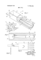
- FIG. 1 is a perspective, partially cutaway, view showing a preferred embodiment of the socket member which is the subject of the invention.
- FIG. 3 is a sectional view taken along line 3--3 in FIG. 2.
- FIGS. 4 and 5 are plan and end views, respectively, of the preferred embodiment of the invention in an initial stage of construction.
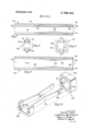
- FIG. 6 is an end view of another embodiment of the invention.
- FIG. 8 is an end view of another embodiment of the invention, similar to that shown in FIG. 6 but showing a generally square sleeve member.
- FIG. 9 is a sectional view taken along line 99 of FIG. 8.
- FIG. II shows a preferred embodiment of female or socket contact 10.
- the contact body is an integral unit including a sleeve or ferrule 12 having a plurality of contact members or arms l4 folded back within the bore of the sleeve and extending longitudinally within the sleeve.
- Each arm 14 includes at least a portion 16 which extends radially inward of the sleeve.
- the arms 14 also include at least a portion 18 lying flat against the inner wall 20 of the sleeve.
- the portion of the arm 16 which extends into the bore is preformed and biased inwardly to provide the arm with substantial spring energy to electrically connect with an associated pin socket (not shown) which may be inserted through opening 22 in the socket.
- an associated pin socket (not shown) which may be inserted through opening 22 in the socket.
- the one-piece socket 10 allows internally extending spring members to be completely flattened against the inner wall of the sleeve 12. This characteristic is especially important in providing a connector system for microminiature environments.
- the integral, folded back contact arms 14 of the invention will allow an associated pin to be made of a maximum relative dimension in order to provide, as much as possible, a structurally sound connection.
- the radially extending portion 16 in the preferred embodiment, is twisted or bent about an axis generally longitudinal of the arm 14, or about an axis which is more longitudinal than lateral to the arm 14.
- the arms 14 shown in FIGS. l-3 are, therefore, deformed-or bent about a line of intersection such as 36.
- This line of intersection 36 serves as the hinge and the basis for the spring energy in the contact system.
- the line is shown to extend from one longitudinal side of the arm to the other at a small acute angle A, which is shown to be substantially less than 45.
- the associated pin or male member makes initial contact with the radially biased portion 16 at a point 34 near the opening or aperture 22 in the socket.
- a firm, aggressive impingement with edge 38 of the biased portion 16 and with portions of surface 40 will result.
- a smooth, controlled insertion force exerted by the associated pin will provide the necessary and required electrical contact and connection between two members.
- the contact between the radially biased portion 16 and an associated pin member will be a line contact extending a substantial axial extent of the pin member.
- a socket in accordance with the invention, may be constructed of any number of arms, and the sleeve may take a variety of cross-sectional configurations
- the preferred embodiment shown in FIGS. 1-3 describes four such integral arms in a square sleeve.
- the angle B shown in FIG. 2 as the angle which the terminal portion of the inwardly extending arms makes with the remaining flat portion 18, governs the radially inward extension of spring portion 16 and, therefore, is indicative of the spring energy residing in the contact arms.
- the unique twisting configuration of portions 16 enables a plurality of arms, such as the four arms 14 shown in FIG. 2, to be utilzied without limiting the inward bias of portions 16.
- the amount of maximum biasing would be limited by the width of the individual arms.
- the placement of all of the portion 16 at angles consistent with one another enables the initial flexure or spring energy to be maximized without total dependence on the width of the arms.
- FIGS. 6-10 alternate embodiments of the invention are shown, wherein the contact structure is similar to that described above,as indicated by the application of identical reference numerals with suffixes a and b added to the corresponding identical elements.
- the contact socket 10a shown in FIGS. 6 and 7 is provided with a generally cylindrical sleeve 12a having integrally attached spring-like contact arms 14a bent over and extending within the sleeve. While two contact arms 140 are shown, it should be apparent that any number of contact arms can be provided and still come within the scope of the invention.
- These bent over integral arms 14a include support portions 180 situated near the opening 22a and at the extremity of the arm. The spring-like pressure and aggressive contact is provided by the portions 16a which are biased inwardly toward each other and provide the necessary spring energy to allow an associated pin (not shown) to be inserted with a smooth, controlled force.
- the portions 18a of the arm advantageously provide intimate contact at all times between the arm and the inner surface of the sleeve. Such contact on either end of the biased portion 16a allows the contact arm to be totally flat against the inner surface upon total compression. Also, the support at either end of the spring portion 16a conserves the energy and gives a greater reaction force than a true cantilever supported spring.
- a further inventive feature is the provision of guides or slots such as 30. These slots receive, and are radially aligned with, associated contact arm members 14a. As a pin is inserted in the socket, the bowed portion will be depressed against the bottom surface of the groove 30. Upon total depression, the diametral distance between arms 14a will be substantially the same as the diametral distance between the inner surfaces 20a. The arms will be substantially flush with the inner wall. In accordance with the discussions above, this will allow for further spring energy to be built into the system and will allow a larger contact pin to be associated with the socket.
- FIGS. 8 through 10 a further embodiment of the invention is shown as a socket 10b having a square cross-sectional configuration As in the embodimetns shown in FIGS. 6 and 7, socket 10b is provided with integral folded back arms 14b having bowed portions 16b providing the spring energy with which electrical contact is achieved and insured. Substantially flat portions 18b are situated at either end of the bowed portions to provide additional support to the structure, as indicated above. Guides or slots 32 may also be provided to increase the effective inner diameter of the socket.
- a further feature of guide or slot means 30 or 32 is i the added stability and structural integrity which they present to a one-piece spring socket member.
- the axial force exerted on the baised portion 16b will force the arm to move in only two directions.
- the arm will be compressed radially against the inner wall 20b and the extremity 18b will be forced in a direction longitudinally of the socket.
- the guide means 32 or 30 will not allow lateral movement of the arms 14a or 14b. Insertion of an associated pin may be accompanied by slight rotation forces which tend to impart lateral movement to arms. This additional stress on a spring member of the size utilized in small environments could be extremely deleterious to the life of the spring member. It is apparent, therefore, that the provision of guides or slot means increases the efficiency of a socket member.
- a blank 42 is provided having portions 12 and 14 which will eventually be formed into the sleeve and contact members respectively.
- the longitudinal edges of this blank will, accordingly, form a seam, such as 26 shown in FIG. 1.
- the tab means 28 may serve to position the workpiece 42 for further deformation and may aid in connection of a wire in portion 24 of the socket.
- This connection may be of any type known in the art, such as crimping or soldering or the like.
- Portions 16 are shown initially deformed at angles substantially .identical to each other. This will provide the advantageous configuration shown in FIG. 2.
- the arms 14 will be folded over on top of portion 12 with portions 18 firmly and intimately contacting the surface of element 12.
- spring portions 16 will be allowed toflex inwardly and will thus retain all of the spring energy for reaction with an associated pin member.
- the body 12 may then be deformed to provide the sleeve with either a square, circular or polygonal cross section.
- a female contact member having integral internal flexing contact elements to establish separable electric contact in an electrical circuit, and more particularly having spring-like portions which are arranged within a sleeve to provide a maximum of spring energy and allow cross section of an associated pin member to be maximized.
- a one-piece electrical contact socket adapted to receive an associated contact pin through the mouth of the bore of the socket, comprising a sleeve member with contact arms positioned within the sleeve and integrally attached thereto at the mouth of the socket, the contact arms extending generally longitudinally within the sleeve and including preformed spring means forming a portion of said arms and biased radially inwardly of the remaining portio'ns'of the associated arms, 2 Iongitudinal segmentof the remaining portions of the arms bearing against a longitudinal segment of the inner wall of the sleeve from the mouth of the socket extending inwardly when the spring means is in a noncompressed state which allows the springmeans to lie flat and bear against the inner wall of the sleeve when said spring means is in a compressed state while maintaining aggressive electrical contact with a pin and maximizing the aperture into which the associated pin is inserted, the portion of the bore including the flat remaining portions of the arms having a cross-sectional area substantially identical to the aperture formed by the mouth
- An electrical contact socket in accordance with claim 1 which includes a plurality of radially spaced spring arms extending inwardly of the sleeve and integrally joined thereto.
- An electrical contact socket adapted to receive a contact pin at one end thereof and to be electrically connected to wire at the other end, comprising a contact portion and sleeve portion, the contact portion including at least one spring arm extending inwardly of the sleeve and integrally joined thereto, said spring arm including a portion formed at an angle to the remaining portion of the spring arm, the angled portion extending generally longitudinal of the spring arm and intersecting the plane of the remaining portion of the spring arm at a line which extends from one longitudinal edge of the spring arm to the other, said line extends at a small acute angle to the longitudinal axis of the spring arm thereby providing aggressive line contact over a substantial length of an associated-contact pin and the spring arm.
- a one-piece electrical contact socket adapted to receive an associated contact pin, comprising a sleeve member with contact arms positioned within the sleeve and integrally attached thereto, the internal walls of the sleeve member including grooves extending longitudinally of the sleeve and adapted to receive the contact arms to stabilize the arm and guide its movement relative to the sleeve upon compression of the spring means, the contact arms extending generally longitudinally of the sleeve and including preformed spring means biased radially inwardly of the associated arms, a portion of the arms bearing against the inner periphery of the sleeve when the spring means is in a noncompressed state which allows the spring means to lie flat against the inner periphery of the sleeve when said spring means is in a compressed state while maintaining aggressive electrical contact with a pin and maximizing the aperture into which the associated pin is inserted.
- a one-piece electrical contact socket adapted to receive an associated contact pin comprising a sleeve member with contact arms positioned within the sleeve and including preformed spring means which are portions of the contact arms twisted about an axis generally longitudinally of the arms and biased radially inwardly of the associated arms, a portion of the arms bearing against the inner periphery of the sleeve when the spring means is in a noncompressed state which allows the spring means to lie flat against the inner periphery of the sleeve when said spring means is in a compressed state while maintaining aggressive electrical contact with a pin and maximizing the aperture into which the associated pin is inserted.
Landscapes
- Connector Housings Or Holding Contact Members (AREA)
- Coupling Device And Connection With Printed Circuit (AREA)
Abstract
An integral electrical contact socket having a sleeve and a plurality of spring arms folded back within the bore of the sleeve and extending longitudinally thereof which enables the contact socket to aggressively impinge an associated contact pin upon its insertion in the socket. The contact arm may be twisted substantially about its longitudinal axis which will provide firm line contact with an associated pin.
Description
United States Patent 1191 Jones et al.
[ CONTACT SOCKET [75] Inventors: Chesley Jones, Westlake Village;
Ougljesa Jules Poupitch, La Jolla,
both of Calif.
[73] Assignee: Illinois Tool Works Inc., Chicago,
Ill.
1221 Filed: Oct. 15,1971
1211 Appl.No.: 189,672
[52] US. Cl. 339/258R, 339/95, 339/258 T [51] InteCl H0lr 9/12 [58] Field of Search 339/258 R, 258 F,
339/258 P, 258 RR, 258 T, 256 R, 256 S, 259 R, 259 F, 217 S, 17 LF,17 R
[56] References Cited UNITED STATES PATENTS 3,38l,262 4/1968 Renaud 339/258 R 3,107,966 10/1963 Bonl-lomme 339/256 R 14 1 Jan. 15, 1974 3,363,224 1/1968 Gluntz 339/258 R 3,713,080 1/1973 Kennedy 339/258 R FOREIGN PATENTS OR APPLICATIONS 1,263,085 4/1961 France 339/258 RR 893,055 4/1962 Great Britain 339/256 R Primary Examiner-Marvin A. Champion Assistant Examiner-William F. Pate, Ill
[ ABSTRACT An integral electrical contact socket having a sleeve and a plurality of spring arms folded back within the bore of the sleeve and extending longitudinally thereof which enables the contact socket to aggressively impinge an associated contact pin upon its insertion in the socket. The contact arm may be twisted substantially about its longitudinal axis which will provide firm line contact with an associated pin.
8 Claims, 10 Drawing Figures Chas/e y Jones Fg 4 I N VENTORS B Ou/jesa Jules Poup/fch Fry Their AH'ys CONTACT SOCKET BACKGROUND OF THE INVENTION The subject matter of the present invention relates generally to an electrical socket contact for use with an associated pin member. In particular, the present invention is concerned with a female contact member having internal flexing contact arms integrally associated with a sleeve or surrounding ferrule member. The contact arms are particularly adapted to provide an efficient electrical contact in microminiature environments.
Existing female contact members for establishing a separable electrical contact in an electric circuit have utilized resilient finger members suitably biased or deformed to engage a male pinmember under spring pressure. One of the principle advantages of such a system is that one socket can accommodate pin members which, due to production tolerance deviation, are slightly smaller or larger than design size. However, most of these prior art efforts to provide a socket memher are of a multi-piece design. For example, a contact cylinder having radially baised armsmay be situated within a preformed ferrule or sleeve. Electrical contact between the cylinder and the ferrule is necessary to complete a circuit between connecting wires and the spring arms. The contact arms of the prior art are generally cantilevered from a fixed cylinder and tend to provide only point contact between a pin and the socket. Unsupported cantilevered contact arms tend to lose spring pressure and consequently cause intermitent electrical contact between the pin and socket. The space requirements in the microminiature environments naturally require maximization of spring energy in the flexingcontact elements to provide a sound electrical contact'while maximizing the size of an associated pin member to provide a firm and efficient mechanical joint.
SUMMARY OF THE INVENTION It is a broad object of the invention to provide a socket connection having internal flexing contact elements which are capable of being efficiently made as a stamping from a single piece of metal. It is an object of the invention to provide a novel, one-piecefemale contact member whichmaximizes spring energy in contact arms in miniature environments.
It is a further object of the invention to provide a contact member which will establish firm line contact with an as osisted pin membe It is yet another object of the invention to provide improved wiping contact over an appreciable surface area of a pin member in a socket member.
The foregoing and other objects and advantages are attained in the present invention by providing a sleeve member having integral spring contact arms folded over within the bore of the sleeve and having portions biased radially inwardly of the sleeve for aggressive contact with a pin member. The integral arms include portions lying flat or closely juxtaposed to the inner wall of the sleeve member which allows theent ire arm member to be pressed flat against the inner surface of 1 the sleeve upon associationwith a pin member. One
embodiment of the invention provides for twisting a portion of the contact arm substantially about the longitudinal axis of the arm to provide aggressive line contact, rather than point contact, with an associated pin member.
BRIEF'DESCRIPTION OF THE DRAWINGS FIG. 1 is a perspective, partially cutaway, view showing a preferred embodiment of the socket member which is the subject of the invention.
FIG. 2 is an end view of the socket contact shown in FIG. 1.
FIG. 3 is a sectional view taken along line 3--3 in FIG. 2. FIGS. 4 and 5 are plan and end views, respectively, of the preferred embodiment of the invention in an initial stage of construction.
FIG. 6 is an end view of another embodiment of the invention.
FIG. 7 is a sectional view taken along the line 77 of FIG. 6.
FIG. 8 is an end view of another embodiment of the invention, similar to that shown in FIG. 6 but showing a generally square sleeve member.
FIG. 9 is a sectional view taken along line 99 of FIG. 8.
FIG. 10 is a perspective, partial cutaway, view of the embodiment shown in FIGS. 8 and 9.
DETAILED DESCRIPTION OF THE PREFERRED EMBODIMENTS Turning now to the drawings, FIG. II shows a preferred embodiment of female or socket contact 10. The contact body is an integral unit including a sleeve or ferrule 12 having a plurality of contact members or arms l4 folded back within the bore of the sleeve and extending longitudinally within the sleeve. Each arm 14 includes at least a portion 16 which extends radially inward of the sleeve. The arms 14 also include at least a portion 18 lying flat against the inner wall 20 of the sleeve. The portion of the arm 16 which extends into the bore is preformed and biased inwardly to provide the arm with substantial spring energy to electrically connect with an associated pin socket (not shown) which may be inserted through opening 22 in the socket. r In accordance withthe teachings of the invention, the one-piece socket 10 allows internally extending spring members to be completely flattened against the inner wall of the sleeve 12. This characteristic is especially important in providing a connector system for microminiature environments. The integral, folded back contact arms 14 of the invention will allow an associated pin to be made of a maximum relative dimension in order to provide, as much as possible, a structurally sound connection. The close juxtapositioning of the arms to the inner walls' will also allow a maximum preforrning or biasing of the inwardly extending portions such as 16 in FIGS. 1-3. It should be apparent that the maximization of spring energy in a contact system is especially important.
Having observed the general details of the socket body 10, attention may now be given to the particular manner of providing and maximizing spring energy to a contact arm such as 14. Attention is drawn to the fact that the radially extending portion 16, in the preferred embodiment, is twisted or bent about an axis generally longitudinal of the arm 14, or about an axis which is more longitudinal than lateral to the arm 14. The arms 14 shown in FIGS. l-3 are, therefore, deformed-or bent about a line of intersection such as 36. This line of intersection 36 serves as the hinge and the basis for the spring energy in the contact system. The line is shown to extend from one longitudinal side of the arm to the other at a small acute angle A, which is shown to be substantially less than 45. As a consequence, the associated pin or male member (not shown) makes initial contact with the radially biased portion 16 at a point 34 near the opening or aperture 22 in the socket. As the pin continues to be inserted in the socket 10, a firm, aggressive impingement with edge 38 of the biased portion 16 and with portions of surface 40 will result. As a consequence, a smooth, controlled insertion force exerted by the associated pin will provide the necessary and required electrical contact and connection between two members. It is to be particularly noted that the contact between the radially biased portion 16 and an associated pin member will be a line contact extending a substantial axial extent of the pin member.
While a socket, in accordance with the invention, may be constructed of any number of arms, and the sleeve may take a variety of cross-sectional configurations, the preferred embodiment shown in FIGS. 1-3 describes four such integral arms in a square sleeve. It is to be particularly noted that the angle B shown in FIG. 2, as the angle which the terminal portion of the inwardly extending arms makes with the remaining flat portion 18, governs the radially inward extension of spring portion 16 and, therefore, is indicative of the spring energy residing in the contact arms. The unique twisting configuration of portions 16 enables a plurality of arms, such as the four arms 14 shown in FIG. 2, to be utilzied without limiting the inward bias of portions 16. If these portions were to be biased in accordance with a normal cantilevered spring arm, the amount of maximum biasing would be limited by the width of the individual arms. In the present invention, the placement of all of the portion 16 at angles consistent with one another enables the initial flexure or spring energy to be maximized without total dependence on the width of the arms.
In FIGS. 6-10 alternate embodiments of the invention are shown, wherein the contact structure is similar to that described above,as indicated by the application of identical reference numerals with suffixes a and b added to the corresponding identical elements. The
structural features of these modifications of the invention also provide for a one-piece socket connector having spring contact arms adapted to completely flatten against the internal wall of the sleeve thereby allowing maximization of spring energy and allowing for maximization of size in the corresponding pin member.
The contact socket 10a shown in FIGS. 6 and 7 is provided with a generally cylindrical sleeve 12a having integrally attached spring-like contact arms 14a bent over and extending within the sleeve. While two contact arms 140 are shown, it should be apparent that any number of contact arms can be provided and still come within the scope of the invention. These bent over integral arms 14a include support portions 180 situated near the opening 22a and at the extremity of the arm. The spring-like pressure and aggressive contact is provided by the portions 16a which are biased inwardly toward each other and provide the necessary spring energy to allow an associated pin (not shown) to be inserted with a smooth, controlled force.
The portions 18a of the arm advantageously provide intimate contact at all times between the arm and the inner surface of the sleeve. Such contact on either end of the biased portion 16a allows the contact arm to be totally flat against the inner surface upon total compression. Also, the support at either end of the spring portion 16a conserves the energy and gives a greater reaction force than a true cantilever supported spring.
While the complete flattening of the integral contact arm 14a against the inner surface will allow the spring energy to be maximized and the dimension of the associated pin to be maximized as discussed above, a further inventive feature is the provision of guides or slots such as 30. These slots receive, and are radially aligned with, associated contact arm members 14a. As a pin is inserted in the socket, the bowed portion will be depressed against the bottom surface of the groove 30. Upon total depression, the diametral distance between arms 14a will be substantially the same as the diametral distance between the inner surfaces 20a. The arms will be substantially flush with the inner wall. In accordance with the discussions above, this will allow for further spring energy to be built into the system and will allow a larger contact pin to be associated with the socket.
In FIGS. 8 through 10, a further embodiment of the invention is shown as a socket 10b having a square cross-sectional configuration As in the embodimetns shown in FIGS. 6 and 7, socket 10b is provided with integral folded back arms 14b having bowed portions 16b providing the spring energy with which electrical contact is achieved and insured. Substantially flat portions 18b are situated at either end of the bowed portions to provide additional support to the structure, as indicated above. Guides or slots 32 may also be provided to increase the effective inner diameter of the socket.
A further feature of guide or slot means 30 or 32 is i the added stability and structural integrity which they present to a one-piece spring socket member. The axial force exerted on the baised portion 16b will force the arm to move in only two directions. The arm will be compressed radially against the inner wall 20b and the extremity 18b will be forced in a direction longitudinally of the socket. The guide means 32 or 30 will not allow lateral movement of the arms 14a or 14b. Insertion of an associated pin may be accompanied by slight rotation forces which tend to impart lateral movement to arms. This additional stress on a spring member of the size utilized in small environments could be extremely deleterious to the life of the spring member. It is apparent, therefore, that the provision of guides or slot means increases the efficiency of a socket member.
For purposes of affording a more complete understanding of the invention, it is advantageous to now provide a description of a mode of manufacturing such a socket. As best shown in FIGS. 4 and 5, a blank 42 is provided having portions 12 and 14 which will eventually be formed into the sleeve and contact members respectively. The longitudinal edges of this blank will, accordingly, form a seam, such as 26 shown in FIG. 1. The tab means 28 may serve to position the workpiece 42 for further deformation and may aid in connection of a wire in portion 24 of the socket. This connection may be of any type known in the art, such as crimping or soldering or the like. Portions 16 are shown initially deformed at angles substantially .identical to each other. This will provide the advantageous configuration shown in FIG. 2. Following this stage in the manufacture, the arms 14 will be folded over on top of portion 12 with portions 18 firmly and intimately contacting the surface of element 12. At the same time, spring portions 16 will be allowed toflex inwardly and will thus retain all of the spring energy for reaction with an associated pin member. After these arms are placed in the folded over position, the body 12 may then be deformed to provide the sleeve with either a square, circular or polygonal cross section.
Thus, it is apparent that there has been provided, in accordance with the invention, a female contact member having integral internal flexing contact elements to establish separable electric contact in an electrical circuit, and more particularly having spring-like portions which are arranged within a sleeve to provide a maximum of spring energy and allow cross section of an associated pin member to be maximized. While the invention has been described in conjunction with specific embodiments thereof, it is evident that many alternatives, modifications, and variations will be apparent to those skilled in the art in light of the foregoing description. Accordingly, it is intended to embrace all such alternatives, modifications, and variations that fall within the spirit and broad scope of the appended claims.
We claim:
l. A one-piece electrical contact socket adapted to receive an associated contact pin through the mouth of the bore of the socket, comprising a sleeve member with contact arms positioned within the sleeve and integrally attached thereto at the mouth of the socket, the contact arms extending generally longitudinally within the sleeve and including preformed spring means forming a portion of said arms and biased radially inwardly of the remaining portio'ns'of the associated arms, 2 Iongitudinal segmentof the remaining portions of the arms bearing against a longitudinal segment of the inner wall of the sleeve from the mouth of the socket extending inwardly when the spring means is in a noncompressed state which allows the springmeans to lie flat and bear against the inner wall of the sleeve when said spring means is in a compressed state while maintaining aggressive electrical contact with a pin and maximizing the aperture into which the associated pin is inserted, the portion of the bore including the flat remaining portions of the arms having a cross-sectional area substantially identical to the aperture formed by the mouth of the socket.
2. An electrical contact socket in accordance with claim 1 which includes a plurality of radially spaced spring arms extending inwardly of the sleeve and integrally joined thereto. a
3. An electrical contact socket in accordance with claim 1 wherein the sleeve portion is polygonal, each side having an integrally connected associated spring arm extending inwardly of the sleeve, each spring arm including substantially identically configured angled portions biased inwardly of the sleeve to provide uniform electrical contact around the mating surfaces of an associated contact pin.
4. An electrical contact socket in accordance with claim 1 wherein the sleeve portion is generally cylindrical.
5. An electrical contact socket adapted to receive a contact pin at one end thereof and to be electrically connected to wire at the other end, comprising a contact portion and sleeve portion, the contact portion including at least one spring arm extending inwardly of the sleeve and integrally joined thereto, said spring arm including a portion formed at an angle to the remaining portion of the spring arm, the angled portion extending generally longitudinal of the spring arm and intersecting the plane of the remaining portion of the spring arm at a line which extends from one longitudinal edge of the spring arm to the other, said line extends at a small acute angle to the longitudinal axis of the spring arm thereby providing aggressive line contact over a substantial length of an associated-contact pin and the spring arm.
6. A one-piece electrical contact socket adapted to receive an associated contact pin, comprising a sleeve member with contact arms positioned within the sleeve and integrally attached thereto, the internal walls of the sleeve member including grooves extending longitudinally of the sleeve and adapted to receive the contact arms to stabilize the arm and guide its movement relative to the sleeve upon compression of the spring means, the contact arms extending generally longitudinally of the sleeve and including preformed spring means biased radially inwardly of the associated arms, a portion of the arms bearing against the inner periphery of the sleeve when the spring means is in a noncompressed state which allows the spring means to lie flat against the inner periphery of the sleeve when said spring means is in a compressed state while maintaining aggressive electrical contact with a pin and maximizing the aperture into which the associated pin is inserted.
7. A contact socket in accordance with claim 1 wherein the grooves are radially aligned with an associated contact arm to allow the arms to become substantially flush with an associated side wall when compressed.
8. A one-piece electrical contact socket adapted to receive an associated contact pin comprising a sleeve member with contact arms positioned within the sleeve and including preformed spring means which are portions of the contact arms twisted about an axis generally longitudinally of the arms and biased radially inwardly of the associated arms, a portion of the arms bearing against the inner periphery of the sleeve when the spring means is in a noncompressed state which allows the spring means to lie flat against the inner periphery of the sleeve when said spring means is in a compressed state while maintaining aggressive electrical contact with a pin and maximizing the aperture into which the associated pin is inserted.
Claims (8)
1. A 1one-piece electrical contact socket adapted to receive an associated contact pin through the mouth of the bore of the socket, comprising a sleeve member with contact arms positioned within the sleeve and integrally attached thereto at the mouth of the socket, the contact arms extending generally longitudinally within the sleeve and including preformed spring means forming a portion of said arms and biased radially inwardly of the remaining portions of the associated arms, a longitudinal segment of the remaining portions of the arms bearing against a longitudinal segment of the inner wall of the sleeve from the mouth of the socket extending inwardly when the spring means is in a noncompressed state which allows the spring means to lie flat and bear against the inner wall of the sleeve when said spring means is in a compressed state while maintaining aggressive electrical contact with a pin and maximizing the aperture into which the associated pin is inserted, the portion of the bore including the flat remaining portions of the arms having a cross-sectional area substantially identical to the aperture formed by the mouth of the socket.
2. An electrical contact socket in accordance with claim 1 which includes a plurality of radially spaced spring arms extending inwardly of the sleeve and integrally joined thereto.
3. An electrical contact socket in accordance with claim 1 wherein the sleeve portion is polygonal, each side having an integrally connected associated spring arm extending inwardly of the sleeve, each spring arm including substantially identically configured angled portions biased inwardly of the sleeve to provide uniform electrical contact around the mating surfaces of an associated contact pin.
4. An electrical contact socket in accordance with claim 1 wherein the sleeve portion is generally cylindrical.
5. An electrical contact socket adapted to receive a contact pin at one end thereof and to be electrically connected to wire at the other end, comprising a contact portion and sleeve portion, the contact portion including at least one spring arm extending inwardly of the sleeve and integrally joined thereto, said spring arm including a portion formed at an angle to the remaining portion of the spring arm, the angled portion extending generally longitudinal of the spring arm and intersecting the plane of the remaining portion of the spring arm at a line which extends from one longitudinal edge of the spring arm to the other, said line extends at a small acute angle to the longitudinal axis of the spring arm thereby providing aggressive line contact over a substantial length of an associated contact pin and the spring arm.
6. A one-piece electrical contact socket adapted to receive an associated contact pin, comprising a sleeve member with contact arms positioned within the sleeve and integrally attached thereto, the internal walls of the sleeve member including grooves extending longitudinally of the sleeve and adapted to receive the contact arms to stabilize the arm and guide its movement relative to the sleeve upon compression of the spring means, the contact arms extending generally longitudinally of the sleeve and including preformed spring means biased radially inwardly of the associated arms, a portion of the arms bearing against the inner periphery of the sleeve when the spring means is in a noncompressed state which allows the spring means to lie flat against the inner periphery of the sleeve when said spring means is in a compressed state while maintaining aggressive electrical contact with a pin and maximizing the aperture into which the associated pin is inserted.
7. A contact socket in accordance with claim 1 wherein the grooves are radially aligned with an associated contact arm to allow the arms to become substantially flush with an associated side wall when compressed.
8. A one-piece electrical contact socket adapted to receive an associated contact pin comprising a sleeve member with contact arms positioned within the sleeve and including preFormed spring means which are portions of the contact arms twisted about an axis generally longitudinally of the arms and biased radially inwardly of the associated arms, a portion of the arms bearing against the inner periphery of the sleeve when the spring means is in a noncompressed state which allows the spring means to lie flat against the inner periphery of the sleeve when said spring means is in a compressed state while maintaining aggressive electrical contact with a pin and maximizing the aperture into which the associated pin is inserted.
Applications Claiming Priority (1)
| Application Number | Priority Date | Filing Date | Title |
|---|---|---|---|
| US18967271A | 1971-10-15 | 1971-10-15 |
Publications (1)
| Publication Number | Publication Date |
|---|---|
| US3786401A true US3786401A (en) | 1974-01-15 |
Family
ID=22698322
Family Applications (1)
| Application Number | Title | Priority Date | Filing Date |
|---|---|---|---|
| US00189672A Expired - Lifetime US3786401A (en) | 1971-10-15 | 1971-10-15 | Contact socket |
Country Status (11)
| Country | Link |
|---|---|
| US (1) | US3786401A (en) |
| JP (1) | JPS5128435B2 (en) |
| AU (1) | AU473018B2 (en) |
| BR (1) | BR7207099D0 (en) |
| CA (1) | CA970060A (en) |
| DE (1) | DE2249705A1 (en) |
| FR (1) | FR2157490A5 (en) |
| GB (1) | GB1404165A (en) |
| HK (1) | HK29576A (en) |
| IT (1) | IT968939B (en) |
| NL (1) | NL7213682A (en) |
Cited By (22)
| Publication number | Priority date | Publication date | Assignee | Title |
|---|---|---|---|---|
| US4025148A (en) * | 1975-08-29 | 1977-05-24 | Bunker Ramo Corporation | Socket for blade-type electrical contacts |
| FR2360188A1 (en) * | 1976-07-26 | 1978-02-24 | Northern Telecom Ltd | FEMALE TERMINAL TO RECEIVE THE EDGE OF CARDS ESPECIALLY FOR TELECOMMUNICATION SYSTEMS |
| US4076369A (en) * | 1976-07-26 | 1978-02-28 | Northern Telecom Limited | Box terminal for card edge receptacles in telecommunications systems and the like |
| USRE31742E (en) * | 1977-10-14 | 1984-11-20 | Allied Corporation | Unitary hooded electrical contact |
| EP0241407A1 (en) * | 1986-04-10 | 1987-10-14 | UNITED TECHNOLOGIES AUTOMOTIVE, Inc. | Electrical receptacle terminal |
| FR2621180A1 (en) * | 1987-09-28 | 1989-03-31 | Francelco Sa | CAGE TYPE ELECTRIC CONTACT TERMINAL |
| US4846609A (en) * | 1987-08-03 | 1989-07-11 | Gte Valenite Corporation | Polygonal cutting insert |
| US4874338A (en) * | 1987-03-31 | 1989-10-17 | Amp Incorporated | Receptacle box terminal with improved contact area |
| US4941853A (en) * | 1989-09-12 | 1990-07-17 | Molex Incorporated | Electrical contact torsion bar systems |
| US5078618A (en) * | 1991-03-05 | 1992-01-07 | Molex Incorporated | Electrical contact socket |
| US5215481A (en) * | 1991-12-13 | 1993-06-01 | Leisey Donald R | Torsion tube electrical connectors |
| US5273455A (en) * | 1993-01-27 | 1993-12-28 | Digital Equipment Corporation | Torsion bar connector |
| US5890936A (en) * | 1996-10-15 | 1999-04-06 | Ut Automotive Dearborn, Inc. | Electrical terminal |
| US5971770A (en) * | 1997-11-05 | 1999-10-26 | Labinal Components And Systems, Inc. | Coaxial connector with bellows spring portion or raised bump |
| US6475040B1 (en) * | 1999-05-28 | 2002-11-05 | Tyco Electronics Corporation | Electrical contact receptacle to mate with round and rectangular pins |
| US20050014422A1 (en) * | 2003-07-15 | 2005-01-20 | Arvind Patel | Female terminal with flexible sidewalls and flat angled contacts |
| US20060035482A1 (en) * | 2004-05-06 | 2006-02-16 | Gary Yasumura | Torsionally-induced contact-force conductors for electrical connector systems |
| DE10236651B4 (en) * | 2001-08-10 | 2007-04-26 | Yazaki Corp. | Plug with spring-loaded contact |
| WO2011067632A1 (en) * | 2009-12-03 | 2011-06-09 | Fci Automotive Holding | Electrical terminal |
| US20110171859A1 (en) * | 2010-01-08 | 2011-07-14 | Fjelstad Joseph C | Connector Constructions for Electronic Applications |
| CN105765795A (en) * | 2013-11-19 | 2016-07-13 | 住友电装株式会社 | Multicontact terminal |
| US10777926B2 (en) * | 2017-02-22 | 2020-09-15 | Autonetworks Technologies, Ltd. | Multi-contact terminal |
Families Citing this family (10)
| Publication number | Priority date | Publication date | Assignee | Title |
|---|---|---|---|---|
| US3815081A (en) * | 1973-05-02 | 1974-06-04 | Illinois Tool Works | Electrical connector |
| GB2000388B (en) * | 1977-06-21 | 1982-01-20 | Bicc Burndy Ltd | Electric contacts |
| US4139256A (en) * | 1977-09-15 | 1979-02-13 | North American Specialties Corp. | Electrical contact and method of making same |
| EP0060024A1 (en) * | 1981-03-05 | 1982-09-15 | General Motors Corporation | Electric socket terminal |
| JPS59161601U (en) * | 1983-04-14 | 1984-10-29 | 三洋電機株式会社 | Resistor pattern for thick film trimming |
| FR2686460B1 (en) * | 1992-01-20 | 1994-03-11 | Labinal Precision Mecanique | FEMALE ELECTRIC CONTACT MEMBER. |
| DE9211819U1 (en) * | 1992-07-07 | 1993-11-04 | Grote & Hartmann | Electrical contact element |
| DE19513588C2 (en) * | 1995-04-10 | 2001-09-27 | Tyco Electronics Logistics Ag | Contact arrangement |
| DE19705509C2 (en) * | 1997-02-13 | 1999-04-29 | Siemens Ag | One-piece contact spring |
| DE102004052378B4 (en) * | 2004-10-28 | 2008-06-19 | Kostal Kontakt Systeme Gmbh | Electrical connector for a motor vehicle |
Citations (6)
| Publication number | Priority date | Publication date | Assignee | Title |
|---|---|---|---|---|
| FR1263085A (en) * | 1960-07-25 | 1961-06-05 | Schaltbau Gmbh | Improvements to power outlets |
| GB893055A (en) * | 1957-08-21 | 1962-04-04 | Plessey Co Ltd | Improvements in or relating to electrical contacts |
| US3107966A (en) * | 1958-02-28 | 1963-10-22 | Curtiss Wright Corp | Electrical connector socket |
| US3363224A (en) * | 1965-10-22 | 1968-01-09 | Amp Inc | Electrical connector |
| US3381262A (en) * | 1965-11-10 | 1968-04-30 | Usine Metallurg Doloise S A | Device for the protection of the elastic member of a coupling |
| US3713080A (en) * | 1971-09-20 | 1973-01-23 | Ford Motor Co | Electrical terminal |
-
1971
- 1971-10-15 US US00189672A patent/US3786401A/en not_active Expired - Lifetime
-
1972
- 1972-09-28 CA CA152,784A patent/CA970060A/en not_active Expired
- 1972-10-03 AU AU47313/72A patent/AU473018B2/en not_active Expired
- 1972-10-10 GB GB4668972A patent/GB1404165A/en not_active Expired
- 1972-10-10 NL NL7213682A patent/NL7213682A/xx unknown
- 1972-10-11 DE DE2249705A patent/DE2249705A1/en active Pending
- 1972-10-12 BR BR7099/72A patent/BR7207099D0/en unknown
- 1972-10-13 FR FR7236411A patent/FR2157490A5/fr not_active Expired
- 1972-10-13 IT IT30458/72A patent/IT968939B/en active
- 1972-10-16 JP JP47103915A patent/JPS5128435B2/ja not_active Expired
-
1976
- 1976-05-20 HK HK295/76*UA patent/HK29576A/en unknown
Patent Citations (6)
| Publication number | Priority date | Publication date | Assignee | Title |
|---|---|---|---|---|
| GB893055A (en) * | 1957-08-21 | 1962-04-04 | Plessey Co Ltd | Improvements in or relating to electrical contacts |
| US3107966A (en) * | 1958-02-28 | 1963-10-22 | Curtiss Wright Corp | Electrical connector socket |
| FR1263085A (en) * | 1960-07-25 | 1961-06-05 | Schaltbau Gmbh | Improvements to power outlets |
| US3363224A (en) * | 1965-10-22 | 1968-01-09 | Amp Inc | Electrical connector |
| US3381262A (en) * | 1965-11-10 | 1968-04-30 | Usine Metallurg Doloise S A | Device for the protection of the elastic member of a coupling |
| US3713080A (en) * | 1971-09-20 | 1973-01-23 | Ford Motor Co | Electrical terminal |
Cited By (33)
| Publication number | Priority date | Publication date | Assignee | Title |
|---|---|---|---|---|
| US4025148A (en) * | 1975-08-29 | 1977-05-24 | Bunker Ramo Corporation | Socket for blade-type electrical contacts |
| FR2360188A1 (en) * | 1976-07-26 | 1978-02-24 | Northern Telecom Ltd | FEMALE TERMINAL TO RECEIVE THE EDGE OF CARDS ESPECIALLY FOR TELECOMMUNICATION SYSTEMS |
| US4076369A (en) * | 1976-07-26 | 1978-02-28 | Northern Telecom Limited | Box terminal for card edge receptacles in telecommunications systems and the like |
| US4152042A (en) * | 1976-07-26 | 1979-05-01 | Northern Telecom Limited | Box terminal for card edge receptacles in telecommunications systems and the like |
| USRE31742E (en) * | 1977-10-14 | 1984-11-20 | Allied Corporation | Unitary hooded electrical contact |
| EP0241407A1 (en) * | 1986-04-10 | 1987-10-14 | UNITED TECHNOLOGIES AUTOMOTIVE, Inc. | Electrical receptacle terminal |
| US4874338A (en) * | 1987-03-31 | 1989-10-17 | Amp Incorporated | Receptacle box terminal with improved contact area |
| US4846609A (en) * | 1987-08-03 | 1989-07-11 | Gte Valenite Corporation | Polygonal cutting insert |
| US4834681A (en) * | 1987-09-28 | 1989-05-30 | Francelco | Electric contact terminal |
| EP0310487A1 (en) * | 1987-09-28 | 1989-04-05 | Francelco, Societe Anonyme | Cage-type electrical contact terminal |
| FR2621180A1 (en) * | 1987-09-28 | 1989-03-31 | Francelco Sa | CAGE TYPE ELECTRIC CONTACT TERMINAL |
| US4941853A (en) * | 1989-09-12 | 1990-07-17 | Molex Incorporated | Electrical contact torsion bar systems |
| US5078618A (en) * | 1991-03-05 | 1992-01-07 | Molex Incorporated | Electrical contact socket |
| US5215481A (en) * | 1991-12-13 | 1993-06-01 | Leisey Donald R | Torsion tube electrical connectors |
| US5273455A (en) * | 1993-01-27 | 1993-12-28 | Digital Equipment Corporation | Torsion bar connector |
| US5890936A (en) * | 1996-10-15 | 1999-04-06 | Ut Automotive Dearborn, Inc. | Electrical terminal |
| US5971770A (en) * | 1997-11-05 | 1999-10-26 | Labinal Components And Systems, Inc. | Coaxial connector with bellows spring portion or raised bump |
| US6475040B1 (en) * | 1999-05-28 | 2002-11-05 | Tyco Electronics Corporation | Electrical contact receptacle to mate with round and rectangular pins |
| DE10236651B4 (en) * | 2001-08-10 | 2007-04-26 | Yazaki Corp. | Plug with spring-loaded contact |
| US20050014422A1 (en) * | 2003-07-15 | 2005-01-20 | Arvind Patel | Female terminal with flexible sidewalls and flat angled contacts |
| US6918798B2 (en) * | 2003-07-15 | 2005-07-19 | Molex Incorporated | Female terminal with flexible sidewalls and flat angled contacts |
| US20060035482A1 (en) * | 2004-05-06 | 2006-02-16 | Gary Yasumura | Torsionally-induced contact-force conductors for electrical connector systems |
| US7845986B2 (en) | 2004-05-06 | 2010-12-07 | Interconnect Portfolio Llc | Torsionally-induced contact-force conductors for electrical connector systems |
| WO2011067632A1 (en) * | 2009-12-03 | 2011-06-09 | Fci Automotive Holding | Electrical terminal |
| US8827756B2 (en) | 2009-12-03 | 2014-09-09 | Delphi International Operations Luxembourg S.A.R.L. | Electrical terminal |
| US8246387B2 (en) | 2010-01-08 | 2012-08-21 | Interconnect Portfolio Llc | Connector constructions for electronic applications |
| US8333617B2 (en) | 2010-01-08 | 2012-12-18 | Interconnect Portfolio Llc | Connector constructions for electronic applications |
| US20110171859A1 (en) * | 2010-01-08 | 2011-07-14 | Fjelstad Joseph C | Connector Constructions for Electronic Applications |
| CN105765795A (en) * | 2013-11-19 | 2016-07-13 | 住友电装株式会社 | Multicontact terminal |
| US20160285187A1 (en) * | 2013-11-19 | 2016-09-29 | Sumitomo Wiring Systems, Ltd. | Multi-contact terminal |
| US9748685B2 (en) * | 2013-11-19 | 2017-08-29 | Sumitomo Wiring Systems, Ltd. | Multi-contact terminal |
| CN105765795B (en) * | 2013-11-19 | 2018-01-12 | 住友电装株式会社 | Multi-contact type terminal |
| US10777926B2 (en) * | 2017-02-22 | 2020-09-15 | Autonetworks Technologies, Ltd. | Multi-contact terminal |
Also Published As
| Publication number | Publication date |
|---|---|
| GB1404165A (en) | 1975-08-28 |
| AU473018B2 (en) | 1976-06-10 |
| NL7213682A (en) | 1973-04-17 |
| DE2249705A1 (en) | 1973-04-19 |
| FR2157490A5 (en) | 1973-06-01 |
| IT968939B (en) | 1974-03-20 |
| JPS4846889A (en) | 1973-07-04 |
| HK29576A (en) | 1976-05-28 |
| JPS5128435B2 (en) | 1976-08-19 |
| AU4731372A (en) | 1974-04-11 |
| CA970060A (en) | 1975-06-24 |
| BR7207099D0 (en) | 1973-09-13 |
Similar Documents
| Publication | Publication Date | Title |
|---|---|---|
| US3786401A (en) | Contact socket | |
| US3972580A (en) | Electrical terminals | |
| US5151056A (en) | Electrical contact system with cantilever mating beams | |
| US6749358B2 (en) | Connector for latching and carrying current capabilities with tooless connection | |
| US3406376A (en) | Socket contact and method of manufacture | |
| KR870001866B1 (en) | Rib cage terminal | |
| JP3428756B2 (en) | Female electrical terminal | |
| US5823833A (en) | Multi-wire locking system | |
| US4838815A (en) | Connector assembly | |
| US2034090A (en) | Wire terminal for electrical conductors | |
| US5620347A (en) | Contact portion structure of female connector terminal | |
| JPH0329282A (en) | Rib cage terminal | |
| US4105277A (en) | Electrical connector | |
| US3924921A (en) | Electrical-pin-and-socket connector | |
| US4983130A (en) | Insulation displacement contact | |
| US4767360A (en) | Electric contact sockets | |
| US5823829A (en) | Connection body's fitting connection structures and sockets structures to hold an electric bulb | |
| WO2024045612A1 (en) | Welding-free jack used for circuit board | |
| JPH0616424B2 (en) | Electrical contact | |
| US3697931A (en) | Electrical plug contact | |
| EP0261839A2 (en) | Spring contact electrical connector assembly | |
| WO2022052350A1 (en) | Crown spring terminal, electric connector jack and electric connector | |
| US5871379A (en) | Butt terminal of two-part construction | |
| US3178676A (en) | Pin contact | |
| US5237742A (en) | Method of producing electrical contact socket |