US3784994A - Air bed - Google Patents
Air bed Download PDFInfo
- Publication number
- US3784994A US3784994A US00309734A US3784994DA US3784994A US 3784994 A US3784994 A US 3784994A US 00309734 A US00309734 A US 00309734A US 3784994D A US3784994D A US 3784994DA US 3784994 A US3784994 A US 3784994A
- Authority
- US
- United States
- Prior art keywords
- air
- distributor
- bed
- disposed
- springs
- Prior art date
- Legal status (The legal status is an assumption and is not a legal conclusion. Google has not performed a legal analysis and makes no representation as to the accuracy of the status listed.)
- Expired - Lifetime
Links
Images


Classifications
-
- A—HUMAN NECESSITIES
- A47—FURNITURE; DOMESTIC ARTICLES OR APPLIANCES; COFFEE MILLS; SPICE MILLS; SUCTION CLEANERS IN GENERAL
- A47C—CHAIRS; SOFAS; BEDS
- A47C23/00—Spring mattresses with rigid frame or forming part of the bedstead, e.g. box springs; Divan bases; Slatted bed bases
- A47C23/002—Spring mattresses with rigid frame or forming part of the bedstead, e.g. box springs; Divan bases; Slatted bed bases with separate resilient support elements, e.g. elastomeric springs arranged in a two-dimensional matrix pattern
-
- A—HUMAN NECESSITIES
- A47—FURNITURE; DOMESTIC ARTICLES OR APPLIANCES; COFFEE MILLS; SPICE MILLS; SUCTION CLEANERS IN GENERAL
- A47C—CHAIRS; SOFAS; BEDS
- A47C27/00—Spring, stuffed or fluid mattresses or cushions specially adapted for chairs, beds or sofas
- A47C27/04—Spring, stuffed or fluid mattresses or cushions specially adapted for chairs, beds or sofas with spring inlays
- A47C27/06—Spring inlays
- A47C27/063—Spring inlays wrapped or otherwise protected
-
- A—HUMAN NECESSITIES
- A47—FURNITURE; DOMESTIC ARTICLES OR APPLIANCES; COFFEE MILLS; SPICE MILLS; SUCTION CLEANERS IN GENERAL
- A47C—CHAIRS; SOFAS; BEDS
- A47C27/00—Spring, stuffed or fluid mattresses or cushions specially adapted for chairs, beds or sofas
- A47C27/08—Fluid mattresses or cushions
- A47C27/081—Fluid mattresses or cushions of pneumatic type
- A47C27/082—Fluid mattresses or cushions of pneumatic type with non-manual inflation, e.g. with electric pumps
Definitions
- An air bed comprising an air spring unit disposed on a support platform and comprising aplurality of parallel, uniformly spaced and vertically aligned inflatable bellows having closed tops and open ends, the tops interlocked and the ends fixed through the platform, and an elastic expandable member coupled to the open end of each bellows and disposed within an expansion-limiting frame.
- An air tube is coupled to each elastic member and leads into an enclosed distributor by engagement with a valve mounted therethrough. Inflation of the combined bellows and elastic member is effected by air pumped from a compressor having an air line leading into the distributor. Closing and opening of the valves is effected by a table within the distributor selectively moveable against the valve release pins.
- This invention relates to beds and bedding and has for its objective the provision of an air bed whose resiliency to support a human body in scientific comfort in repose is provided for by a support member encompassing a plurality of spaced, vertically-aligned, independent air springs, or air-inflated bellows, disposed therein beneath a soft protective layer of material and maintained with a constant air content, each air spring coupled to an elastic member, whereby bodily weight applied to the support member not only causes temporary compression of each air spring, in accordance with the amount of weight borne by it, but allows some of the contained air to pass into and inflate the elastic attached member within designated limits, thereby to provide greater and more uniform adaptability of the support member to the contours of the human body, the support member returning to its original shape with the removal of the imposed weight.
- my invention provides for an air bed including a support member in which a plurality of spaced air springs or bellows are supported in vertical alignment below a protective layer of material, with each air spring in communication with an elastic and inflatable member and individually filled with air to a preselected, uniform pressure. When filled with air to the desired pressure the volume of air contained in each air spring and communicating elastic member remains constant, regardless of pressure or compression.
- the air springs When pressure is applied, as by a reclining body, to the support member the air springs will compress independently, in accordance with the degree of weight or pressure applied, thereby to fit the contours of the reclining body, with the air contained in each air spring not only compressing to a specific degree, but also relieved by the escape of some of the air into the elastic, inflatable member, and thereby providing a higher degree of resiliency and buoyancy to the entire bed, with the extent of inflation of the elastic member limited by a restrictive member.
- the elastic members With the release of the pressure applied to the bed, as by removal of its occupant, the elastic members will constrict to original size, returning the displaced air to the respective air springs and thereby restoring them to their original size and shape.
- Compressor means is provided to inflate the air springs to deisred pressure and means to deflate them, as well as to regulate the firmness of the support member, or its softness, depending on the individual taste of the user.
- a second important object of my invention lies in the provision of an air bed wherein application of bodily weight will cause temporary displacement of the contained air, as well as compression.
- a third important object of my invention lies in the provision of an air bed wherein depression of specific areas thereof is accomplished by the extent of weight disposed, thereby conforming the bed to the contours of the reclining body.
- a fourth important object of my invention will be found in the provision of an air bed wherein shifting of bodily weight will cause appropriate adjustment of the air springs.
- a fifth important object of my invention lies in pro viding an air bed whose firmness can be quickly and easily adjusted to individual taste of the user.
- Still another important object of my invention lies in the provision of an air bed composed of individual units which can be separately replaced where required.
- FIG. 1 is a perspective view of a preferred embodiment of my invention
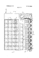
- FIG. 2 is a top plan view of the embodiment of FIG. 1, partly broken away, to show disposition of the air springs;
- FIG. 3 is a cross-sectional view, taken on lines 3-3 of FIG. 2;
- FIG. 4 is an enlarged cross-sectional view showing one of the air springs in normal expansion, partly broken away;
- FIG. 5 is a view similar to FIG. 4, showing compression of the air spring
- FIG. 6 is a cross-sectional view, taken on lines 6-6 of FIG. 4;
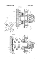
- FIG. 7 is an enlarged top view, partly in section, of the distributor
- FIG. 8 is an enlarged exploded view of the distributor of FIG. 7;
- FIG. 9 is a cross-sectional view of the distributor of FIGS. 7 and 8.
- FIG. 10 is a cross-sectional view, taken on lines ll0 of FIG. 9.
- my air bed comprises a support frame 12, formed with side walls 14 and end walls 16, and provided with a platform 18 fitted into grooves in the walls 14 and 16 and adapted to support the air spring unit 20.
- a support frame 12 formed with side walls 14 and end walls 16, and provided with a platform 18 fitted into grooves in the walls 14 and 16 and adapted to support the air spring unit 20.
- an enclosed headboard housing 22 Disposed adajcent the head portion of the bed 10 there is provided an enclosed headboard housing 22 having a recessed front wall section 24, adapted to accomodate the end wall 16 of the frame 12, so as to bring the rear end of the air spring unit 20 into close abutment with the unrecessed front wall 26.
- the top surface 28 of the headboard housing 22 is inclined, as shown, and is provided with an opening to seat a control panel 30, by means of which the air bed 10 may be inflated and deflated, as will be hereinafter described.
- the surface 28 may also provided other openings or support for appliances, such as a lamp or radio(neither shown).
- the air spring unit 20 contains a plurality of uniformly sapced air springs 32 vertically disposed in parallel relationship throughout the unit 20, as shown.
- Each air spring 32 is preferably, but not necessarily, composed ofa heavy gauge plastic material, molded in the shape of a collapsible bellows, suitably creased, as shown, and adapted to compress with the application of pressure on its top surface 34, so that its enlarged areas converge, as is seen in FIG. 5.
- the angular sides of the air springs 32 may be provided with stiffener elements 33, if desired, to give them greater rigidity under pressure, as shown in FIGS. 4 and 5.
- Each air spring 32 is provided with a closed flat top surface 34, on which is mounted a steel ring 36 locked in place by support rings 38 and 40, the ring 36 being provided with four spaced arcuate slots 42 around its outer perimeter, by which the top of each air spring 32 is secured in position with respect to adjoining air springs 32, in tensioned spaced relationship, by tie members 44 whose converging ends are secured together by central tie rings 46, as shown in FIG. 2.
- each air spring is enlarged to form a pedestal 48 extending into a reduced circular flange 50 adapted to extend through a circular aperture 52 in the frame platform 18, with the lower surface 54 of the pedestal 48 abutting and resting upon the upper surface of the platform 18, whereby each air spring 32 is thus supported in a fixed, vertical position.
- Each air spring 32 is thus disposed so that air can be introduced thereinto through the flange 50.
- An elastic inflatable ball 56 is secured to the air spring 32 by the engagement of its enlarged neck 58 around the flange 50, secured thereto by a locking ring 60, the ball 56 being reinforced around its outer area by a network 62 of elastic stiffener bands, as shown in FIGS. 4 and 5.
- the end of the ball 56, opposite its neck 58 is provided with an opening 64 to which is coupled the end of an air tube 66, through which air is introduced into the combined air spring 32 and ball 56, as will hereinafter be described.
- Expansion of the ball 56 is limited by the circumference of a rigid basket element 68, in which the ball 56 is disposed, the basket element 68 being secured to sapced ribs 70 extending from the undersurface of the platform 18, as by screws 72 threaded into the ribs 70 through a support member 74 formed integral with the basket element 68.
- the air spring unit 20 is provided with a suitable support layer 76, composed of foam rubber topped by cotton or wool, or other similar materials, as is well known in the art, which is disposed across the tops of the air springs 32, the entire unit 20 including a casing 78 fitted around the layer 76 and air springs 32, the bottom surface of the casing 78 provided with apertures 80 through which the pedestal flanges 50 extend below the platform 18, the upper surface of the casing 78 being tufted, as shown in FIG. 1.
- a suitable support layer 76 composed of foam rubber topped by cotton or wool, or other similar materials, as is well known in the art, which is disposed across the tops of the air springs 32, the entire unit 20 including a casing 78 fitted around the layer 76 and air springs 32, the bottom surface of the casing 78 provided with apertures 80 through which the pedestal flanges 50 extend below the platform 18, the upper surface of the casing 78 being tufted, as shown in FIG. 1.
- the air tubes 66 one of which is coupled to each ball 56, extend through the frame 12, passing through an opening 82 in wall 16 and an opening 84 in the headboard housing 22, wherein each air tube 66 is coupled to a valve 86 disposed through the top of a distributor 88, which is mounted to the undersurface 90 of the inclined surface 28 of the headboard housing 22, as shown, the end of the distributor 88 thereby forming the panel 30 exposed through the opening in the surface 28 heretofore described, and the valves 86 providing communication between the air tubes 66 and the interior of the distributor 88.
- the air tubes 66 pass through, and are supported by, rings(not shown) secured in the bottom surfaces of the ribs 70.
- a compressor 92 is secured to the floor of the headboard housing 22, as by bolts(not shown) and is provided with an air line 94 leading into the interior of the distributor 88, and is connected to a suitable source of electric current(not shown), with its activating wires terminating in a switch 130 mounted on the control panel 30.
- the distributor 88 comprises a housing 96 provided with a closure member 98, the latter containing the air valves 86 whose locking pins 100 extend into the housing 96, and the closure member 98 is secured in air-tight engagement with the housing 96 by screws 102 threaded through extensions 104 of the closure member 98 into extensions 106 of the housing 96, a gasket 108 being disposed thereinbetween.
- the distributor 88 contains a footed table 110 provided with bores 112 extending through its feet 114, and is thereby adapted to seat around corresponding rods 116 fitted in the floor of the housing 96 and extending into the closure member 98, whereby the table 110 is adapted to be raised and lowered within the housing 96, in raised position to depress the valve pins 100 to open the valves 86, and in lowered position to release the pins 100, thereby closing the valves 86.
- Raising and lowering of the table 110 is effected by means of a shaft 118 rotatively journeled through the end walls of the housing 96 below the table 110, and provided with a pair of eccentric cams 120 disposed in abutment with the undersurface of the table 110, the shaft 118 extending through an end wall of the housing 96 to be exposed through the control panel 30, and terminating in a knob 122 fitted with and indicator symbor 124 to show the position of the table 110 within the distributor 88, the knob 122 constituting means for rotation of the shaft 118.
- Tension springs 117 are mounted around the rods 116 between the table 110 and the closure member 98 to force the table 110 away from the valve pins 100 when the shaft 118 is rotated to lower the table 110.
- the distributor is further provided with an exhaust valve 126 fitted through its end wall, and a monometer 128, both in communication with the interior of the distributor 86, the valve 126, manometer 128, knob 122 and switch 130 being all mounted in the end wall of the distributor 88 forming its control panel 30.
- My air bed is inflated for use, through operation of the control panel, as follows: switch 130 is thrown to activate the compressor 92 and force air therefrom through its air line 94 into the distributor 88. Knob 122 is then turned to raise the table 110 to depress the valve pins 100, whereby the air is uniformly forced through the air tubes 66 into the combined air springs 32 and elastic balls 56, the operator meanwhile noting the air pressure on the manometer 128.
- the knob 122 is rotated to its original position, releasing the valve pins 100 from the table 100, the closing off all of the valves 86, the compressor 92 is then deactivated.
- the air pressure can be selectively reduced by rotating the knob 122 to open the valves 86, and depressing the exhaust valve 126 to exhaust air from the air springs 32 and balls 56 as it passes back into the distributor 88, until the pressure descends to the desired reduction. In this manner the firmness or softness of the bed 10 can be adjusted quickly and easily, to any degree desired.
- any part of the air bed 10 malfunctions, such as, for example, an air spring 32, elastic ball 56, or air tube 66, the part is easily and quickly replaceable with a new part, as is obvious from the disclosed construction.
- An air bed comprising a support framework provided with an horizontal platform and an air spring unit disposed thereon and comprising a plurality of bellowsshaped inflatable members constituting air springs having flat closed tops and open bottoms, the air springs disposed in parallel, sapced, vertical alignment, with their top surfaces interlocked and their open bottoms fixedly disposed through apertures formed in the platform, an elastic expandable member coupled to the open bottom of each air spring and providing intercommunication therewith, a rigid enclosure member disposed around each elastic member and adapted to limit its exapnsion, an air tube coupled to each elastic member, means to inflate the combined air springs and elastic members, means to indicate the air pressure therein, means to selectively open and close the air tubes, means to adjust the air pressure and means to exhaust the air from the combined air springs and elastic members.
- the means to inflate the combined air springs and elastic members comprising a distributor including a housing sealed by a closure member, a plurality of valves mounted through the closure member and opening outwardly therefrom and having their release pins disposed in alignment within the housing, one of the air tubes coupled to the exposed end of each of the valves, and a compressor provided with an air line leading into the distributor.
- the means to selectively open and close the air tubes comprising a plurality of rods fixed in the floor of the distributor housing and extending into the closure member, a table reciprocally mounted on the rods and a shaft journeled through the housing below the table and provided with ecentric cams abutting the table undersurface, whereby rotation of the shaft alternately raises the table to depress the valve pins and lowers the table to release the valve pins, one end of the shaft extending from the distributor and terminating in a knob for manual rotation of the shaft.
- An air bed as described in claim 6, the means to exhaust the air from the combined air springs and elastic members and to adjust the air pressure comprising an exhaust valve disposed through the end wall of the distrbutor and in communication with the interior thereof.
Abstract
An air bed comprising an air spring unit disposed on a support platform and comprising a plurality of parallel, uniformly spaced and vertically aligned inflatable bellows having closed tops and open ends, the tops interlocked and the ends fixed through the platform, and an elastic expandable member coupled to the open end of each bellows and disposed within an expansion-limiting frame. An air tube is coupled to each elastic member and leads into an enclosed distributor by engagement with a valve mounted therethrough. Inflation of the combined bellows and elastic member is effected by air pumped from a compressor having an air line leading into the distributor. Closing and opening of the valves is effected by a table within the distributor selectively moveable against the valve release pins.
Description
United States Patent [191 Kery [4 1 Jan. 15, 1974 AIR BED [76] Inventor: Edmund Kery, 908 E. 55th St., New
York, N.Y. 11234 22 Filed: Nov. 27, 1972 211 Appl.No.:309,734
[52] US. Cl. 5/348, 297/284 [51] lint. Cl. A47c 27/08 [58] Field of Search 5/348, 349, 350,
5/351, D16. 2; 297/DlG. 8, BIG. 3, 284
[56] References Cited UNITED STATES PATENTS 3,605,145 9/1971 Graebe 5/348 3,192,541 7/1965 Moore i. 5/349 2,897,520 8/1959 Bradford 5/348 2,814,053 '1 1/1957 Sevcik 5/348 2,779,034 l/l957 Arpin 5/348 2,350,711 6/1944 Amos 297/DlG. 8
Primary Examiner-Francis K. Zugel Assistant ExaminerAndrew M. Calvert AttorneySydney B. Schlessel [5 7 ABSTRACT An air bed comprising an air spring unit disposed on a support platform and comprising aplurality of parallel, uniformly spaced and vertically aligned inflatable bellows having closed tops and open ends, the tops interlocked and the ends fixed through the platform, and an elastic expandable member coupled to the open end of each bellows and disposed within an expansion-limiting frame. An air tube is coupled to each elastic member and leads into an enclosed distributor by engagement with a valve mounted therethrough. Inflation of the combined bellows and elastic member is effected by air pumped from a compressor having an air line leading into the distributor. Closing and opening of the valves is effected by a table within the distributor selectively moveable against the valve release pins.
AIR BED BACKGROUND OF THE INVENTION 1. Field of the Invention This invention relates to beds and bedding and has for its objective the provision of an air bed whose resiliency to support a human body in scientific comfort in repose is provided for by a support member encompassing a plurality of spaced, vertically-aligned, independent air springs, or air-inflated bellows, disposed therein beneath a soft protective layer of material and maintained with a constant air content, each air spring coupled to an elastic member, whereby bodily weight applied to the support member not only causes temporary compression of each air spring, in accordance with the amount of weight borne by it, but allows some of the contained air to pass into and inflate the elastic attached member within designated limits, thereby to provide greater and more uniform adaptability of the support member to the contours of the human body, the support member returning to its original shape with the removal of the imposed weight.
2. Prior Art In the prior state of the art there have been provided various forms of air cushions and mattresses. Some of these devices provide for their inflation with air as a single unit, so that when pressure is applied to one area of the cushion or mattress air is displaced to areas not subjected to pressure, thereby making them bulky, misshaped and wobbly, contributing very little to comfort. In other forms the cushions and mattresses are subdivided into partitioned areas, with each partitioned area individually filled with air. When pressures are applied to any specific partitioned area or areas, resiliency is limited to compression of the contained air, since the latter is confined to the limits of its enclosure. In further forms of the present art air mattresses or supports are provided with individually, air-filled bellows disposed across the area of the mattress, so that depression of specific bellows is encompassed by the degree of pressure applied to each. In these forms, however,
resiliency is restricted to the extent to which the en- I trapped air is capable of compression, with no provision for temporary escape of a part of the contained air from its bellows, so that the greater the-pressure applied, the greater the resistance to such pressure.
BRIEF SUMMARY OF THE INVENTION The aforementioned disadvantages are overcome by my invention, which provides for an air bed including a support member in which a plurality of spaced air springs or bellows are supported in vertical alignment below a protective layer of material, with each air spring in communication with an elastic and inflatable member and individually filled with air to a preselected, uniform pressure. When filled with air to the desired pressure the volume of air contained in each air spring and communicating elastic member remains constant, regardless of pressure or compression. When pressure is applied, as by a reclining body, to the support member the air springs will compress independently, in accordance with the degree of weight or pressure applied, thereby to fit the contours of the reclining body, with the air contained in each air spring not only compressing to a specific degree, but also relieved by the escape of some of the air into the elastic, inflatable member, and thereby providing a higher degree of resiliency and buoyancy to the entire bed, with the extent of inflation of the elastic member limited by a restrictive member. With the release of the pressure applied to the bed, as by removal of its occupant, the elastic members will constrict to original size, returning the displaced air to the respective air springs and thereby restoring them to their original size and shape. As is obvious, shifting of the body on the bed will cause some of the air springs to compress further and some to expand, depending on the shift of weight, so that the support member continues to follow the body contours. Compressor means is provided to inflate the air springs to deisred pressure and means to deflate them, as well as to regulate the firmness of the support member, or its softness, depending on the individual taste of the user.
It is therefore the principal object of my invention to provide an air bed wherein the resiliency and buoyancy of the bed is adjustable to any desired degree of firmness or softness.
A second important object of my invention lies in the provision of an air bed wherein application of bodily weight will cause temporary displacement of the contained air, as well as compression.
A third important object of my invention lies in the provision of an air bed wherein depression of specific areas thereof is accomplished by the extent of weight disposed, thereby conforming the bed to the contours of the reclining body.
A fourth important object of my invention will be found in the provision of an air bed wherein shifting of bodily weight will cause appropriate adjustment of the air springs.
A fifth important object of my invention lies in pro viding an air bed whose firmness can be quickly and easily adjusted to individual taste of the user.
Still another important object of my invention lies in the provision of an air bed composed of individual units which can be separately replaced where required.
These and other salient objects, advantages and functional features of my invention, together with the novel features of construction, composition and arrangement of parts, will become more readily apparent from an examination of the following description, taken with the accompanying drawings, wherein:
BRIEF DESCRIPTION OF THE DRAWINGS FIG. 1 is a perspective view of a preferred embodiment of my invention;
FIG. 2 is a top plan view of the embodiment of FIG. 1, partly broken away, to show disposition of the air springs;
FIG. 3 is a cross-sectional view, taken on lines 3-3 of FIG. 2;
FIG. 4 is an enlarged cross-sectional view showing one of the air springs in normal expansion, partly broken away;
FIG. 5 is a view similar to FIG. 4, showing compression of the air spring;
FIG. 6 is a cross-sectional view, taken on lines 6-6 of FIG. 4;
FIG. 7 is an enlarged top view, partly in section, of the distributor;
FIG. 8 is an enlarged exploded view of the distributor of FIG. 7;
FIG. 9 is a cross-sectional view of the distributor of FIGS. 7 and 8; and
FIG. 10 is a cross-sectional view, taken on lines ll0 of FIG. 9.
Similar reference characters designate similar parts throughout the different views.
DETAILED DESCRIPTION OF THE INVENTION Illustrative of the embodiment shown in the drawings, my air bed comprises a support frame 12, formed with side walls 14 and end walls 16, and provided with a platform 18 fitted into grooves in the walls 14 and 16 and adapted to support the air spring unit 20. Disposed adajcent the head portion of the bed 10 there is provided an enclosed headboard housing 22 having a recessed front wall section 24, adapted to accomodate the end wall 16 of the frame 12, so as to bring the rear end of the air spring unit 20 into close abutment with the unrecessed front wall 26. The top surface 28 of the headboard housing 22 is inclined, as shown, and is provided with an opening to seat a control panel 30, by means of which the air bed 10 may be inflated and deflated, as will be hereinafter described. The surface 28 may also provided other openings or support for appliances, such as a lamp or radio(neither shown).
Referring now to FIGS. 26, the air spring unit 20 contains a plurality of uniformly sapced air springs 32 vertically disposed in parallel relationship throughout the unit 20, as shown. Each air spring 32 is preferably, but not necessarily, composed ofa heavy gauge plastic material, molded in the shape of a collapsible bellows, suitably creased, as shown, and adapted to compress with the application of pressure on its top surface 34, so that its enlarged areas converge, as is seen in FIG. 5. The angular sides of the air springs 32 may be provided with stiffener elements 33, if desired, to give them greater rigidity under pressure, as shown in FIGS. 4 and 5. Each air spring 32 is provided with a closed flat top surface 34, on which is mounted a steel ring 36 locked in place by support rings 38 and 40, the ring 36 being provided with four spaced arcuate slots 42 around its outer perimeter, by which the top of each air spring 32 is secured in position with respect to adjoining air springs 32, in tensioned spaced relationship, by tie members 44 whose converging ends are secured together by central tie rings 46, as shown in FIG. 2.
The bottom end of each air spring is enlarged to form a pedestal 48 extending into a reduced circular flange 50 adapted to extend through a circular aperture 52 in the frame platform 18, with the lower surface 54 of the pedestal 48 abutting and resting upon the upper surface of the platform 18, whereby each air spring 32 is thus supported in a fixed, vertical position. Each air spring 32 is thus disposed so that air can be introduced thereinto through the flange 50. An elastic inflatable ball 56 is secured to the air spring 32 by the engagement of its enlarged neck 58 around the flange 50, secured thereto by a locking ring 60, the ball 56 being reinforced around its outer area by a network 62 of elastic stiffener bands, as shown in FIGS. 4 and 5. The end of the ball 56, opposite its neck 58 is provided with an opening 64 to which is coupled the end of an air tube 66, through which air is introduced into the combined air spring 32 and ball 56, as will hereinafter be described. Expansion of the ball 56 is limited by the circumference of a rigid basket element 68, in which the ball 56 is disposed, the basket element 68 being secured to sapced ribs 70 extending from the undersurface of the platform 18, as by screws 72 threaded into the ribs 70 through a support member 74 formed integral with the basket element 68.
The air spring unit 20 is provided with a suitable support layer 76, composed of foam rubber topped by cotton or wool, or other similar materials, as is well known in the art, which is disposed across the tops of the air springs 32, the entire unit 20 including a casing 78 fitted around the layer 76 and air springs 32, the bottom surface of the casing 78 provided with apertures 80 through which the pedestal flanges 50 extend below the platform 18, the upper surface of the casing 78 being tufted, as shown in FIG. 1.
Coming now to FIG. 3, the air tubes 66, one of which is coupled to each ball 56, extend through the frame 12, passing through an opening 82 in wall 16 and an opening 84 in the headboard housing 22, wherein each air tube 66 is coupled to a valve 86 disposed through the top of a distributor 88, which is mounted to the undersurface 90 of the inclined surface 28 of the headboard housing 22, as shown, the end of the distributor 88 thereby forming the panel 30 exposed through the opening in the surface 28 heretofore described, and the valves 86 providing communication between the air tubes 66 and the interior of the distributor 88. The air tubes 66 pass through, and are supported by, rings(not shown) secured in the bottom surfaces of the ribs 70. A compressor 92 is secured to the floor of the headboard housing 22, as by bolts(not shown) and is provided with an air line 94 leading into the interior of the distributor 88, and is connected to a suitable source of electric current(not shown), with its activating wires terminating in a switch 130 mounted on the control panel 30.
Referring now to FIGS. 7-10, the distributor 88 comprises a housing 96 provided with a closure member 98, the latter containing the air valves 86 whose locking pins 100 extend into the housing 96, and the closure member 98 is secured in air-tight engagement with the housing 96 by screws 102 threaded through extensions 104 of the closure member 98 into extensions 106 of the housing 96, a gasket 108 being disposed thereinbetween.
The distributor 88 contains a footed table 110 provided with bores 112 extending through its feet 114, and is thereby adapted to seat around corresponding rods 116 fitted in the floor of the housing 96 and extending into the closure member 98, whereby the table 110 is adapted to be raised and lowered within the housing 96, in raised position to depress the valve pins 100 to open the valves 86, and in lowered position to release the pins 100, thereby closing the valves 86. Raising and lowering of the table 110 is effected by means of a shaft 118 rotatively journeled through the end walls of the housing 96 below the table 110, and provided with a pair of eccentric cams 120 disposed in abutment with the undersurface of the table 110, the shaft 118 extending through an end wall of the housing 96 to be exposed through the control panel 30, and terminating in a knob 122 fitted with and indicator symbor 124 to show the position of the table 110 within the distributor 88, the knob 122 constituting means for rotation of the shaft 118. Tension springs 117 are mounted around the rods 116 between the table 110 and the closure member 98 to force the table 110 away from the valve pins 100 when the shaft 118 is rotated to lower the table 110.
The distributor is further provided with an exhaust valve 126 fitted through its end wall, and a monometer 128, both in communication with the interior of the distributor 86, the valve 126, manometer 128, knob 122 and switch 130 being all mounted in the end wall of the distributor 88 forming its control panel 30.
OPERATION OF THE INVENTION My air bed is inflated for use, through operation of the control panel, as follows: switch 130 is thrown to activate the compressor 92 and force air therefrom through its air line 94 into the distributor 88. Knob 122 is then turned to raise the table 110 to depress the valve pins 100, whereby the air is uniformly forced through the air tubes 66 into the combined air springs 32 and elastic balls 56, the operator meanwhile noting the air pressure on the manometer 128. When the air springs 32 and balls 56 have been inflated to the desired air pressure, as indicated on the manometer 128, the knob 122 is rotated to its original position, releasing the valve pins 100 from the table 100, the closing off all of the valves 86, the compressor 92 is then deactivated. After testing the bed 10 for firmness, if the bed 10 is considered toosoft for comfort, the above procedure is repeated to increase the air pressure. On the other hand, should the bed 10 be considered too hard or firm for comfort, the air pressure can be selectively reduced by rotating the knob 122 to open the valves 86, and depressing the exhaust valve 126 to exhaust air from the air springs 32 and balls 56 as it passes back into the distributor 88, until the pressure descends to the desired reduction. In this manner the firmness or softness of the bed 10 can be adjusted quickly and easily, to any degree desired.
In the event that any part of the air bed 10 malfunctions, such as, for example, an air spring 32, elastic ball 56, or air tube 66, the part is easily and quickly replaceable with a new part, as is obvious from the disclosed construction.
It is further to be noted that the embodiment shown and described is by way of illustration and not of limitation, and that various changes may be made in the construction, composition and arrangement of parts without limitation upon or departure from the spirit and scope of the invention, or sacrificing any of the advantages thereof inherent therein, all of which are claimed.
Having described my invention, I claim:
1. An air bed comprising a support framework provided with an horizontal platform and an air spring unit disposed thereon and comprising a plurality of bellowsshaped inflatable members constituting air springs having flat closed tops and open bottoms, the air springs disposed in parallel, sapced, vertical alignment, with their top surfaces interlocked and their open bottoms fixedly disposed through apertures formed in the platform, an elastic expandable member coupled to the open bottom of each air spring and providing intercommunication therewith, a rigid enclosure member disposed around each elastic member and adapted to limit its exapnsion, an air tube coupled to each elastic member, means to inflate the combined air springs and elastic members, means to indicate the air pressure therein, means to selectively open and close the air tubes, means to adjust the air pressure and means to exhaust the air from the combined air springs and elastic members.
2. An air bed as described in claim 1, the air spring unit being further provided with a layer of soft material disposed across the top surfaces of the air springs and a casing enclosing the layer of soft material and the air springs.
3. An air bed as described in claim 2, the means to inflate the combined air springs and elastic members comprising a distributor including a housing sealed by a closure member, a plurality of valves mounted through the closure member and opening outwardly therefrom and having their release pins disposed in alignment within the housing, one of the air tubes coupled to the exposed end of each of the valves, and a compressor provided with an air line leading into the distributor.
4. An air bed as described in claim 3, the means to register the air pressure within the combined air springs and elastic members comprising a manometer mounted on the outer surface of the distributor and in communication with the interior thereof.
5. An air bed as decribed in claim 4, the means to selectively open and close the air tubes comprising a plurality of rods fixed in the floor of the distributor housing and extending into the closure member, a table reciprocally mounted on the rods and a shaft journeled through the housing below the table and provided with ecentric cams abutting the table undersurface, whereby rotation of the shaft alternately raises the table to depress the valve pins and lowers the table to release the valve pins, one end of the shaft extending from the distributor and terminating in a knob for manual rotation of the shaft.
6. An air bed as described in claim 5, a spring mounted around each of the rods between the table and the closure member and adapted to tension the table against the closure member.
7. An air bed as described in claim 6, the means to exhaust the air from the combined air springs and elastic members and to adjust the air pressure comprising an exhaust valve disposed through the end wall of the distrbutor and in communication with the interior thereof.
Claims (7)
1. An air bed comprising a support framework provided with an horizontal platform and an air spring unit disposed thereon and comprising a plurality of bellows-shaped inflatable members constituting air springs having flat closed tops and open bottoms, the air springs disposed in parallel, spaced, vertical alignment, with their top surfaces interlocked and their open bottoms fixedly disposed through apertures formed in the platform, an elastic expandable member coupled to the open bottom of each air spring and providing intercommunication therewith, a rigid enclosure member disposed around each elastic member and adapted to limit its expansion, an air tube coupled to each elastic member, means to inflate the combined air springs and elastic members, means to indicate the air pressure therein, means to selectively open and close the air tubes, means to adjust the air pressure and means to exhaust the air from the combined air springs and elastic members.
2. An air bed as described in claim 1, the air spring unit being further provided with a layer of soft material disposed across the top surfaces of the air springs and a casing enclosing the layer of soft material and the air springs.
3. An air bed as described in claim 2, the means to inflate the combined air springs and elastic members comprising a distributor including a housing sealed by a closure member, a plurality of valves mounted through the closure member and opening outwardly therefrom and having their release pins disposed in alignment within the housing, one of the air tubes coupled to the exposed end of each of the valves, and a compressor provided with an air line leading into the distributor.
4. An air bed as described in claim 3, the means to register the air pressure within the combined air springs and elastic members comprising a manometer mounted on the outer surface of the distributor and in communication with the interior thereof.
5. An air bed as decribed in claim 4, the means to selectively open and close the air tubes comprising a plurality of rods fixed in the floor of the distributor housing and extending into the closure member, a table reciprocally mounted on the rods and a shaft journeled through the housing below the table and provided with eccentric cams abutting the table undersurface, whereby rotation of the shaft alternately raises the table to depress the valve pins and lowers the table to release the valve pins, one end of the shaft extending from the distributor and terminating in a knob for manual rotation of the shaft.
6. An air bed as described in claim 5, a spring mounted around each of the rods between the table and the closure member and adapted to tension the table against the closure member.
7. An air bed as described in claim 6, the means to exhaust the air from the combined air springs and elastic members and to adjust the air pressure comprising an exhaust valve disposed through the end wall of the distRibutor and in communication with the interior thereof.
Applications Claiming Priority (1)
| Application Number | Priority Date | Filing Date | Title |
|---|---|---|---|
| US30973472A | 1972-11-27 | 1972-11-27 |
Publications (1)
| Publication Number | Publication Date |
|---|---|
| US3784994A true US3784994A (en) | 1974-01-15 |
Family
ID=23199447
Family Applications (1)
| Application Number | Title | Priority Date | Filing Date |
|---|---|---|---|
| US00309734A Expired - Lifetime US3784994A (en) | 1972-11-27 | 1972-11-27 | Air bed |
Country Status (1)
| Country | Link |
|---|---|
| US (1) | US3784994A (en) |
Cited By (32)
| Publication number | Priority date | Publication date | Assignee | Title |
|---|---|---|---|---|
| US3879776A (en) * | 1974-01-10 | 1975-04-29 | Morris Solen | Variable tension fluid mattress |
| US4224706A (en) * | 1978-10-16 | 1980-09-30 | Dial-A-Firm, Inc. | Pneumatic bed |
| US4491364A (en) * | 1981-02-19 | 1985-01-01 | Aisin Seiki Kabushiki Kaisha | Lumber support system for a vehicle seat |
| US4491157A (en) * | 1981-03-06 | 1985-01-01 | Aisin Seiki Kabushiki Kaisha | Valve assembly for air bag control |
| US4570676A (en) * | 1982-03-18 | 1986-02-18 | Aisin Seiki Kabushiki Kaisha | Lumbar support air valve assembly |
| US4766628A (en) * | 1986-01-21 | 1988-08-30 | Walker Robert A | Air mattress with filler check valve and cap therefor |
| US4788729A (en) * | 1985-04-14 | 1988-12-06 | Walker Robert A | Air mattress with audible pressure relief valve |
| US4799276A (en) * | 1986-09-15 | 1989-01-24 | Ehud Kadish | Body rest with means for preventing pressure sores |
| US4829616A (en) * | 1985-10-25 | 1989-05-16 | Walker Robert A | Air control system for air bed |
| US4862921A (en) * | 1988-07-29 | 1989-09-05 | Jack Hess | Air distribution system for air support convalescent beds |
| US4897890A (en) * | 1983-01-05 | 1990-02-06 | Walker Robert A | Air control system for air bed |
| US4945590A (en) * | 1988-11-08 | 1990-08-07 | Ogura Jewel Industry Co., Ltd. | Valve for fluid mat and apparatus for controlling an attitude assumed by fluid mat |
| US5408711A (en) * | 1994-05-17 | 1995-04-25 | Mcclelland; Marion | Air mattress assembly |
| US5433506A (en) * | 1993-11-30 | 1995-07-18 | Jensen; Hans C. | Pneumatically-cushioned chair |
| US5606754A (en) * | 1989-03-09 | 1997-03-04 | Ssi Medical Services, Inc. | Vibratory patient support system |
| US5983429A (en) * | 1994-02-15 | 1999-11-16 | Stacy; Richard B. | Method and apparatus for supporting and for supplying therapy to a patient |
| US6457192B2 (en) | 2000-10-04 | 2002-10-01 | Harrison Choi | Air bed with elevated and self-expanding support structure |
| US20060059630A1 (en) * | 2004-09-23 | 2006-03-23 | Romano James J | Mattress having an air pressure indicator |
| US20060191538A1 (en) * | 2001-10-22 | 2006-08-31 | Map Medizin-Technologie Gmbh | Application device for breathing mask arrangement |
| US20080181795A1 (en) * | 2007-01-26 | 2008-07-31 | Rapid Air Llc (A Wisconsin Limited Liability Company) | Multiple configuration air mattress pump system |
| US20110047703A1 (en) * | 2009-08-31 | 2011-03-03 | Jean-Francois Tarsaud | Lateral tilt device |
| US20110271447A1 (en) * | 2010-05-04 | 2011-11-10 | Yos Soetanto Theosabrata | Mattress and bedding system |
| US8863338B2 (en) | 2010-06-02 | 2014-10-21 | Touchsensor Technologies, Llc | Therapeutic support device allowing capillary blood flow |
| US9216122B2 (en) | 2010-10-05 | 2015-12-22 | Touchsensor Technologies, Llc | Support apparatus, system and method |
| US20180042408A1 (en) * | 2016-08-15 | 2018-02-15 | Hsien-Ta Huang | Air-bag-lifting sleep pillow structure |
| US20180199726A1 (en) * | 2015-07-14 | 2018-07-19 | Ammique Limited | Improvements in and relating to beds |
| US10575654B2 (en) | 2016-10-28 | 2020-03-03 | Sleep Number Corporation | Air manifold |
| US10888173B2 (en) * | 2016-10-28 | 2021-01-12 | Sleep Number Corporation | Air controller with vibration isolators |
| US10993546B2 (en) | 2016-10-28 | 2021-05-04 | Sleep Number Corporation | Noise reducing plunger |
| US20220411063A1 (en) * | 2021-06-25 | 2022-12-29 | Airbus Operations Gmbh | Inflatable suspended ceiling for a vehicle compartment, in particular for a passenger cabin of an aircraft |
| US11832728B2 (en) | 2021-08-24 | 2023-12-05 | Sleep Number Corporation | Controlling vibration transmission within inflation assemblies |
| US11950702B2 (en) | 2021-04-07 | 2024-04-09 | Sleep Number Corporation | Noise reducing plunger |
Citations (6)
| Publication number | Priority date | Publication date | Assignee | Title |
|---|---|---|---|---|
| US2350711A (en) * | 1941-12-12 | 1944-06-06 | Timothy B Mccarthy | Bellows cushion for upholstery |
| US2779034A (en) * | 1954-01-26 | 1957-01-29 | Frank D Arpin | Firmness adjustment for mattresses |
| US2814053A (en) * | 1954-09-02 | 1957-11-26 | Burton Dixie Corp | Inflatable mattress |
| US2897520A (en) * | 1958-02-04 | 1959-08-04 | Wylie B Bradford | Resilient support assembly |
| US3192541A (en) * | 1962-03-19 | 1965-07-06 | Boyd S Moore | Contourable pneumatic cushions |
| US3605145A (en) * | 1968-12-05 | 1971-09-20 | Robert H Graebe | Body support |
-
1972
- 1972-11-27 US US00309734A patent/US3784994A/en not_active Expired - Lifetime
Patent Citations (6)
| Publication number | Priority date | Publication date | Assignee | Title |
|---|---|---|---|---|
| US2350711A (en) * | 1941-12-12 | 1944-06-06 | Timothy B Mccarthy | Bellows cushion for upholstery |
| US2779034A (en) * | 1954-01-26 | 1957-01-29 | Frank D Arpin | Firmness adjustment for mattresses |
| US2814053A (en) * | 1954-09-02 | 1957-11-26 | Burton Dixie Corp | Inflatable mattress |
| US2897520A (en) * | 1958-02-04 | 1959-08-04 | Wylie B Bradford | Resilient support assembly |
| US3192541A (en) * | 1962-03-19 | 1965-07-06 | Boyd S Moore | Contourable pneumatic cushions |
| US3605145A (en) * | 1968-12-05 | 1971-09-20 | Robert H Graebe | Body support |
Cited By (51)
| Publication number | Priority date | Publication date | Assignee | Title |
|---|---|---|---|---|
| US3879776A (en) * | 1974-01-10 | 1975-04-29 | Morris Solen | Variable tension fluid mattress |
| US4224706A (en) * | 1978-10-16 | 1980-09-30 | Dial-A-Firm, Inc. | Pneumatic bed |
| US4306322A (en) * | 1978-10-16 | 1981-12-22 | Dial-A-Firm, Inc. | Pneumatic bed assembly |
| US4491364A (en) * | 1981-02-19 | 1985-01-01 | Aisin Seiki Kabushiki Kaisha | Lumber support system for a vehicle seat |
| US4491157A (en) * | 1981-03-06 | 1985-01-01 | Aisin Seiki Kabushiki Kaisha | Valve assembly for air bag control |
| US4570676A (en) * | 1982-03-18 | 1986-02-18 | Aisin Seiki Kabushiki Kaisha | Lumbar support air valve assembly |
| US4890344A (en) * | 1983-01-05 | 1990-01-02 | Walker Robert A | Air control system for air bed |
| US4897890A (en) * | 1983-01-05 | 1990-02-06 | Walker Robert A | Air control system for air bed |
| US4788729A (en) * | 1985-04-14 | 1988-12-06 | Walker Robert A | Air mattress with audible pressure relief valve |
| US4829616A (en) * | 1985-10-25 | 1989-05-16 | Walker Robert A | Air control system for air bed |
| US4766628A (en) * | 1986-01-21 | 1988-08-30 | Walker Robert A | Air mattress with filler check valve and cap therefor |
| US4799276A (en) * | 1986-09-15 | 1989-01-24 | Ehud Kadish | Body rest with means for preventing pressure sores |
| US4862921A (en) * | 1988-07-29 | 1989-09-05 | Jack Hess | Air distribution system for air support convalescent beds |
| US4945590A (en) * | 1988-11-08 | 1990-08-07 | Ogura Jewel Industry Co., Ltd. | Valve for fluid mat and apparatus for controlling an attitude assumed by fluid mat |
| US6820640B2 (en) | 1989-03-09 | 2004-11-23 | Hill-Rom Services, Inc. | Vibratory patient support system |
| US5606754A (en) * | 1989-03-09 | 1997-03-04 | Ssi Medical Services, Inc. | Vibratory patient support system |
| US6098222A (en) * | 1989-03-09 | 2000-08-08 | Hill-Rom Company, Inc. | Vibratory patient support system |
| US6415814B1 (en) | 1989-03-09 | 2002-07-09 | Hill-Rom Services, Inc. | Vibratory patient support system |
| US20050034764A1 (en) * | 1989-03-09 | 2005-02-17 | Hanh Barry D. | Patient support system |
| US5433506A (en) * | 1993-11-30 | 1995-07-18 | Jensen; Hans C. | Pneumatically-cushioned chair |
| US5983429A (en) * | 1994-02-15 | 1999-11-16 | Stacy; Richard B. | Method and apparatus for supporting and for supplying therapy to a patient |
| US5408711A (en) * | 1994-05-17 | 1995-04-25 | Mcclelland; Marion | Air mattress assembly |
| US6457192B2 (en) | 2000-10-04 | 2002-10-01 | Harrison Choi | Air bed with elevated and self-expanding support structure |
| US20060191538A1 (en) * | 2001-10-22 | 2006-08-31 | Map Medizin-Technologie Gmbh | Application device for breathing mask arrangement |
| US20060059630A1 (en) * | 2004-09-23 | 2006-03-23 | Romano James J | Mattress having an air pressure indicator |
| US7287290B2 (en) * | 2004-09-23 | 2007-10-30 | Hill-Rom Services, Inc. | Mattress having an air pressure indicator |
| US8707488B2 (en) | 2007-01-26 | 2014-04-29 | Rapid Air Llc | Multiple configuration air mattress pump system |
| US20080181795A1 (en) * | 2007-01-26 | 2008-07-31 | Rapid Air Llc (A Wisconsin Limited Liability Company) | Multiple configuration air mattress pump system |
| US7886387B2 (en) | 2007-01-26 | 2011-02-15 | Rapid Air Llc | Multiple configuration air mattress pump system |
| US8601622B1 (en) | 2009-08-31 | 2013-12-10 | Hill-Rom Industries S.A. | Patient support apparatus including a lateral tilt device |
| US8429774B2 (en) | 2009-08-31 | 2013-04-30 | Hill-Rom Industries Sa | Lateral tilt device |
| US20110047703A1 (en) * | 2009-08-31 | 2011-03-03 | Jean-Francois Tarsaud | Lateral tilt device |
| US20110271447A1 (en) * | 2010-05-04 | 2011-11-10 | Yos Soetanto Theosabrata | Mattress and bedding system |
| US8863336B2 (en) * | 2010-05-04 | 2014-10-21 | Yos Soetanto Theosabrata | Mattress and bedding system |
| US8863338B2 (en) | 2010-06-02 | 2014-10-21 | Touchsensor Technologies, Llc | Therapeutic support device allowing capillary blood flow |
| US10758441B2 (en) | 2010-10-05 | 2020-09-01 | Dabir Surfaces, Inc. | Support apparatus, system and method |
| US9216122B2 (en) | 2010-10-05 | 2015-12-22 | Touchsensor Technologies, Llc | Support apparatus, system and method |
| US11672715B2 (en) | 2010-10-05 | 2023-06-13 | Dabir Surfaces, Inc. | Support apparatus, system and method |
| US20180199726A1 (en) * | 2015-07-14 | 2018-07-19 | Ammique Limited | Improvements in and relating to beds |
| US11019933B2 (en) * | 2015-07-14 | 2021-06-01 | Ammique Limited | Beds |
| US10772446B2 (en) * | 2016-08-15 | 2020-09-15 | Hsien-Ta Huang | Air-bag-lifting sleep pillow structure |
| US20180042408A1 (en) * | 2016-08-15 | 2018-02-15 | Hsien-Ta Huang | Air-bag-lifting sleep pillow structure |
| US10575654B2 (en) | 2016-10-28 | 2020-03-03 | Sleep Number Corporation | Air manifold |
| US10888173B2 (en) * | 2016-10-28 | 2021-01-12 | Sleep Number Corporation | Air controller with vibration isolators |
| US10993546B2 (en) | 2016-10-28 | 2021-05-04 | Sleep Number Corporation | Noise reducing plunger |
| US20210251392A1 (en) * | 2016-10-28 | 2021-08-19 | Sleep Number Corporation | Air Controller With Vibration Isolators |
| US11426006B2 (en) | 2016-10-28 | 2022-08-30 | Sleep Number Corporation | Air manifold |
| US11937705B2 (en) | 2016-10-28 | 2024-03-26 | Sleep Number Corporation | Air bed system with an air manifold |
| US11950702B2 (en) | 2021-04-07 | 2024-04-09 | Sleep Number Corporation | Noise reducing plunger |
| US20220411063A1 (en) * | 2021-06-25 | 2022-12-29 | Airbus Operations Gmbh | Inflatable suspended ceiling for a vehicle compartment, in particular for a passenger cabin of an aircraft |
| US11832728B2 (en) | 2021-08-24 | 2023-12-05 | Sleep Number Corporation | Controlling vibration transmission within inflation assemblies |
Similar Documents
| Publication | Publication Date | Title |
|---|---|---|
| US3784994A (en) | Air bed | |
| US7424760B2 (en) | Body support, comfort device | |
| US3653083A (en) | Bed pad | |
| US5113539A (en) | Adjustable firmness coil spring mattress with inflatable tubes | |
| US8225444B2 (en) | Inflatable device forming mattresses and cushions | |
| US7000276B2 (en) | Body support surface comfort device | |
| US3792501A (en) | Air chairs and convertible sofas | |
| US4688283A (en) | Mattress which conforms to body profile | |
| US6212719B1 (en) | Air massager cushioning device | |
| US3795018A (en) | Adjustable bed | |
| US6745420B2 (en) | Adjustable foam and coil spring mattress combination | |
| US4213213A (en) | Support device | |
| US3303518A (en) | Inflatable mattresses, pillows and cushions | |
| US3644949A (en) | Multiple inflatable pillow | |
| US5815862A (en) | Portable orthopedic bed | |
| US3766579A (en) | Water bed | |
| US20020148045A1 (en) | Pressure adjustable foam support apparatus | |
| US5070559A (en) | Adjustable spinal support | |
| US6546579B1 (en) | Conforming air and foam support device | |
| US2150434A (en) | Furniture | |
| US3685063A (en) | Furniture | |
| US2485199A (en) | Resilient unit for bedsprings, chairs, and the like | |
| US1873212A (en) | Cushion | |
| EP0757899B1 (en) | Mattress with adjustment of the firmness | |
| CN219763849U (en) | Self-adaptive mattress for lateral position operation and operating table thereof |