US3773446A - Device for moulding parts to be sintered - Google Patents
Device for moulding parts to be sintered Download PDFInfo
- Publication number
- US3773446A US3773446A US00174325A US3773446DA US3773446A US 3773446 A US3773446 A US 3773446A US 00174325 A US00174325 A US 00174325A US 3773446D A US3773446D A US 3773446DA US 3773446 A US3773446 A US 3773446A
- Authority
- US
- United States
- Prior art keywords
- pressure plate
- die
- dies
- movable
- punches
- Prior art date
- Legal status (The legal status is an assumption and is not a legal conclusion. Google has not performed a legal analysis and makes no representation as to the accuracy of the status listed.)
- Expired - Lifetime
Links
Images


Classifications
-
- B—PERFORMING OPERATIONS; TRANSPORTING
- B22—CASTING; POWDER METALLURGY
- B22F—WORKING METALLIC POWDER; MANUFACTURE OF ARTICLES FROM METALLIC POWDER; MAKING METALLIC POWDER; APPARATUS OR DEVICES SPECIALLY ADAPTED FOR METALLIC POWDER
- B22F3/00—Manufacture of workpieces or articles from metallic powder characterised by the manner of compacting or sintering; Apparatus specially adapted therefor ; Presses and furnaces
- B22F3/02—Compacting only
- B22F3/03—Press-moulding apparatus therefor
-
- B—PERFORMING OPERATIONS; TRANSPORTING
- B01—PHYSICAL OR CHEMICAL PROCESSES OR APPARATUS IN GENERAL
- B01J—CHEMICAL OR PHYSICAL PROCESSES, e.g. CATALYSIS OR COLLOID CHEMISTRY; THEIR RELEVANT APPARATUS
- B01J3/00—Processes of utilising sub-atmospheric or super-atmospheric pressure to effect chemical or physical change of matter; Apparatus therefor
- B01J3/04—Pressure vessels, e.g. autoclaves
Definitions
- pressure plate operated by the punch extending through the movable die engages the movable die and is also locked to the fixed die during the compression stroke of the punches to insure that the dies do not separate during the compression stroke.
- the present invention relates to a device for moulding parts to be sintered, by compressing powdered materials.
- Various such devices are known for moulding parts which generally have cylindrical or prismatic shapes and can be constructed of two or more integral parts of different section. These parts are normally compressed by means of a group of punches, each of which has a section equal to one of the portions of the part, whilst other punches each have a section equal to that of a portion not covered by another portion of the part, i.e., of a partion which projects relative to another portion.
- the object of the present invention is to ensure perfect contact between the dies during the compression of the powdered material, preventing the formation of flashes on the side surface of the molded part.
- a device for moulding parts to be sintered by compressing powdered materials comprising at least one pair of punches shiftable axially towards each other in order to compress the powder, the punches co-operating with a pair of dies capable of being'separated parallel to the BRIEF DESCRIPTION OF THE DRAWINGS
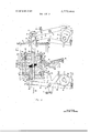
- FIG. 1 is a cross-section of a moulding device embodying the invention in one working position
- FIG. 2 is the section of FIG. 1 in another working position
- FIG. 3 is a partial section along the line III III of FIG. 2;
- FIG. 4 is a partial section along the line IV IV of FIG. 3.
- the moulding device is incorporated in a press having a fixed frame, of which a portion 5 is shown in FIG. 1.
- the moulding device comprises a pair of dies 6 and 7, of which the die 6 is fixed on the portion 5 of the frame, whilst the die 7 is connected through two columns 8 to a plate 9 sliding on another portion 10 of the frame of the press.
- the plate 9 is integral with a sleeve 11 and a flange 12.
- a peg 13 of a lever 14 is engaged between the plate 9 and the flange 12.
- the lever 14 fulcrumed on a fixed pivot 16 and is thrust in an anticlockwise direction by a spring 17 which normally keeps the die 7 against the fixed die 6.
- the spring 17 thus avoids breakage which could be caused by entry of foreign bodies, for example bits of previously moulded parts, which could get between the open dies 6 and 7.
- the lever 14 is provided with a peg 19 capable of cooperating with a cam 18. This latter is fixed on an actuating shaft 20 of the press, which shaft is capable of being rotated cylindrically in a clockwise direction.
- the two dies 6 and 7 are provided for the moulding of a part 21, visible in section in FIG. 2, which consists of a pair of integral cams 22 and 23 provided with a central hole 24 for mounting the cams on a shaft.
- the part 21 is therefore formed from two generally cylindrical or prismatic portions, having a different crosssection and joined at the plane of variation of the section, which plane is perpendicular to the axes of the two dies 6 and 7.
- the part 21 has furthermore, in each of the two portions 22 and 23, part which project relative to the other portion, which require, for the extraction, the opening of the two dies 6 and 7. The extraction is effected upwardly from the fixed die 6.
- the lower punch 25 is provided with two flanges 27, between which there is engaged a peg 28 of a lever 29. This latter is fulcrumed on a fixed pivot 30 and is provided with another peg 31 which normally rests, through the action of a spring 32, against a cam 33 (FIG. I) which is fixed on a second shaft 34 capable of rotating in a clockwise direction in synchronism with the shaft 20.
- the punch 26, in its turn, is provided with a pair of flanges 36, between which there is engaged a peg 37 of a lever 38 fulcrumed on a fixed pivot 39.
- the lever 38 is provided with another peg 40 which normally rests through the action of a spring 41 against a cam 42 fixed on the shaft 20.
- the two punches 25 and 26 have, internally, an axial hole 43 and 44 respectively, into which there can pass a rod 46 in order to allow the moulding of the hole 24 of the part 21.
- the press further comprises a duct 47 for feeding the metal powder 48 into the dies 6 and 7.
- the duct 47 is displaceable cyclically in known manner on the die 7 and on to a plate 4 coplanar with the die 7, from the position of FIG. 1 to that of FIG. 2.
- the moulding device comprises means for positve locking capable of keeping the dies 6 and 7 in contact during the compression.
- these locking means comprise a pressure plate 51, which is provided at the bottom with a projection 52 capable of resting against the die 7, but normally removed from it as in FIG. 1.
- the plate 51 is provided with a central hole 53, by means of which it is guided by the punch 26. This latter is provided, in its turn, with a flange 54, which is connected to the plate 51 through two resilient couplings.
- Each resilient coupling is formed by a compression spring 56 and by a small pillar 57 fixed at the bottom on the plate 51 and sliding in the flange 54.
- Each pillar 57 is provided with a flange 58 normally resting against the flange 54.
- the locking means of the matrix comprise, furthermore, a member which can be actuated for positively coupling the pressure plate 51 with the fixed die 6.
- This member is constituted by a ring 61, which is rotary in a groove 62 of the fixed die 6.
- the ring 61 (FIG. 3) is provided with a peg 63 connected with a lot of play to a hole of a slider 64. This is fulcrumed on a pin 66 (FIG. 1) carried by a lever 67 fulcrummed on the pin 30.
- the lever 67 is provided with a peg 68 normally resting against a cam 69 on the shaft 34 under the action of a spring 71 which tends to cause the lever 67 to rotate in a clockwise direction.
- the ring 61 is furthermore provided with two diametrically opposed teeth 72, of which only one is visible in FIG. 3.
- Each tooth 72 has a radial edge 73 and the lower surface 74 slightly inclined (FIG. 4).
- Each tooth 72 is capable of cooperating with a shoulder of a hooked appendage 75 of a corresponding column 76 (FIG. 1) passing through a corresponding hole 77 of the movable die 7.
- the two columns 76 are threaded at the top and are fixed in two threaded holes of the pressure plate 51 so as to be able to be adjusted in height.
- the columns 76 are then fixed in the desired position by lock nuts 78.
- each column 76 is provided with an upper surface or shoulder 79 (FIG. 4) inclined substantially like that of the corresponding tooth 72 and with a lower surface 80 inclined in the opposite direction and capable of cooperating with the radial edge 73 of the corresponding tooth 72.
- the punch 26 is in the high position whilst the movable die 7 rests against the fixed die 6, as indicated in FIG. 1. Furthermore, the ring 61 is in the position of FIG. 3, so that the peg 68 rests against the cam 69.
- the duct 47 is above the cen- "tral portion of the movable die 7, so as to effect the charging of the two dies 6 and 7 with the metal powder 48 in a manner known per se. Subsequently the duct 47 is slid on to the plate 49 outside the path of the plate 51.
- the plate 51 reaches the movable die 7 before the punch 26.
- the spring 71 then urges the lever 67 to rotate in a clockwise direction and through the slider 64 forces the ring 61 in the clockwise direction, so that the teeth 72 through the inclined surfaces 74 and 79 force the columns 76 downwards.
- the peg 68 does not succeed in going back into contact with the cam 69 (FIG. 2), whereby it is the action of the spring 71 which keeps the teeth 72 wedged above the appendages 75, thus locking the die 7 positively with the die 6.
- the cam 42 allows the spring 41 to move the punch 26 upwards, whilst the cam 33 causes the punch to shift subsequently upwards and thus expel the part 21 from the die 6.
- the part 21 is then removed, in a manner known per se.
- the cam 69 then allows the spring 71 to bring back the lever 67 and hence the ring 61 into the position of rest indicated in FIG. 1.
- the cam 18 allows the spring 17 to bring the die 6 back into contact with the die 7.
- the duct 47 moves over the matrix 7, efiecting once more the filling of the powder 48.
- the actuation of the punches 25 and 26, of the die 7 and of the plate 51 can be effected by hydraulic means, instead of through the action of cams.
- a device for moulding parts to be sintered by compressing powdered materials comprising a pair of dies movable with respect to one another between a moulding position in aligned cooperating relationship and an open position separated from one another so that the moulded part can be removed,
- locking means engaging and forcibly urging said dies together when said dies are in said moulding position to prevent separation of said dies during the compressing of said powdered material.
- a device wherein one of said dies is movable and the other of said dies is fixed, and wherein said locking means comprises a pressure plate operated by one of said punches and engaging said movable die when said die is in said moulding position and said punches are operated in said compression stroke.
- said locking means further comprises means for positively engaging It thus becomes clear that the action of the punch 25 i and coupling said pressure plate to said fixed die and for transmitting a force urging said pressure plate and a and a locking member carried by said fixed die and engaging said locking shafts, said locking member applying to at least one said locking shaft a force for urging said pressure plate and said fixed die together while said pressure plate engages said movable die.
- each of said locking shafts includes an inclined shaft shoulder and said locking member comprises an annular ring disposed about said fixed die and rotatably movable thereabout, said annular ring having corresponding inclined ring shoulders to engage said shaft shoulder and being coupled to means for rotating said annular ring to engage said shoulders, whereby rotation of said ring causes camming action between said inclined shoulders resulting in a displacing force being applied to said locking shaft and urging together of said pressure plate and said fixed die.
- a device wherein one of said punches is associated with said movable die and the other of said punches is associated with said fixed die, said pressure plate being operated by said one punch.
- a device wherein said pressure plate is disposed about said one punch and is relatively movable with respect thereto, and said device further comprises flange means attached to said one punch and spaced from said pressure plate and resilient compression means interposed between said flange means and said pressure plate, whereby said pressure plate is operated into engagement with said movable die through said resilient compression means.
- a device further comprising L disengaging means connected between said flange means and said pressure plate to move said pressure plate out of engagement with said movable die when said one punch retracts after said compression stroke.
- said resilient compression means comprises at least one compression spring
- said disengaging means comprises a shaft coaxial with each of said springs and having a pair of flanges at opposite ends engaging said pressure plate and said flange means to limit the outward relative movement thereof.
- a device wherein said one punch extends through an opening in said movable die substantially perpendicularly to said movable die and said pressure plate is slidable on the outer surfaces of said one punch, said pressure plate pressing said movable die against said fixed die, and wherein said compression means and said disengaging means are disposed about said die.
Abstract
A device for moulding parts to be sintered by compressing powdered materials held between a fixed die and a movable die. A pair of punches extending through the dies compresses the powdered material. A pressure plate operated by the punch extending through the movable die engages the movable die and is also locked to the fixed die during the compression stroke of the punches to insure that the dies do not separate during the compression stroke.
Description
[ Nov. 20, 1973 United States Patent [191 Borrini 00000 10 577 55 MMM QM SZZMHHSS 244/5522 4 52244 044 M m "t" mew mm L M mmm a t u u" Me a "near mm a "w ennfi g ua u -mme QvwKsTJH 98823796 56555556 99999999 HHUHHHHH 5249549 80967 62323 30 8295987 ,3 ,9 ,3 23222223 E B W O M T ,A m a p R .W. 9 A .b 0 V. P .m m W n & H
0 .l) l B n o n D 0 .m 9 a e m 1 0 M T 4 l 2 M w r m g R a u 0 B .11 A Fm R m m E t n WT m g m E m m w m DS I A F l. 1.1 1 4 5 3 2 5 7 7 2 .l. [.l. 1.
[21] Appl. No.: 174,325
[30] Foreign Application Priority Data ABSTRACT Sept. 10, 1970 70042 A770 425/78 425/450 425/354, A device for moulding parts to be sintered by comressing powdered materials held between a fixed and a movable die. A pair 0 B30b ll/02 425/78, 242, 249, 425/251, 450, 149
f punches extending through the dies compresses the powdered material. A
pressure plate operated by the punch extending through the movable die engages the movable die and is also locked to the fixed die during the compression stroke of the punches to insure that the dies do not separate during the compression stroke.
[58] Fieldof Search......................
- [56] References Cited UNITED STATES PATENTS 10 Claims, 4 Drawing Figures 3,020,589 2/1962 Maritano 2,570,989 10/1951 Seelig.......
1,607,389 11/1926 Claus 2,389,169 11/1945 Stacy PATENIinuuvzo ms 3,773 sum 1 or 3 INVENTOR. BARTOLOMEO BORRINI PAIENTEDnnvzo 197a SHEET 2 [IF 3 Fig.
INVENTOR. BARTOLOMEO BORRINI SHEET 3 OF 3 PATENTEflmlvzo I973 Fig.
INVENTOR. BARTOLOMEO BORRINI DEVICE FOR MOULDING PARTS TO BE SINTERED BACKGROUND OF THE INVENTION The present invention relates to a device for moulding parts to be sintered, by compressing powdered materials. Various such devices are known for moulding parts which generally have cylindrical or prismatic shapes and can be constructed of two or more integral parts of different section. These parts are normally compressed by means of a group of punches, each of which has a section equal to one of the portions of the part, whilst other punches each have a section equal to that of a portion not covered by another portion of the part, i.e., of a partion which projects relative to another portion.
In a known moulding device, for the purposes of allowing the extraction of parts having portions projecting with regard to others, it has already been proposed to use two dies, one of which is movable away from the other in the direction of movement of the punches. The two dies mate at the plane of variation of section of the part during the compression. This device, has nevertheless, the disadvantage of the difficulty of keeping the two dies fitting perfectly together during the compression. Therefore, particularly in the case where the projections of one portion of the part with regard to the other are very pronounced, the action of the opposing punch tends to detach the movable die from the fixed one, whereby flashes form on the surface of the compressed part.
SUMMARY OF THE INVENTION The object of the present invention is to ensure perfect contact between the dies during the compression of the powdered material, preventing the formation of flashes on the side surface of the molded part.
According to the present invention, there is provided a device for moulding parts to be sintered by compressing powdered materials, comprising at least one pair of punches shiftable axially towards each other in order to compress the powder, the punches co-operating with a pair of dies capable of being'separated parallel to the BRIEF DESCRIPTION OF THE DRAWINGS The invention will be described in more detail, by way of example, with reference to the accompanying drawings, in which:
FIG. 1 is a cross-section of a moulding device embodying the invention in one working position;
FIG. 2 is the section of FIG. 1 in another working position;
FIG. 3 is a partial section along the line III III of FIG. 2; and
FIG. 4 is a partial section along the line IV IV of FIG. 3.
DESCRIPTION OF A PREFERRED EMBODIMENT The moulding device is incorporated in a press having a fixed frame, of which a portion 5 is shown in FIG. 1. The moulding device comprises a pair of dies 6 and 7, of which the die 6 is fixed on the portion 5 of the frame, whilst the die 7 is connected through two columns 8 to a plate 9 sliding on another portion 10 of the frame of the press. The plate 9 is integral with a sleeve 11 and a flange 12. A peg 13 of a lever 14 is engaged between the plate 9 and the flange 12. The lever 14 fulcrumed on a fixed pivot 16 and is thrust in an anticlockwise direction by a spring 17 which normally keeps the die 7 against the fixed die 6. The spring 17 thus avoids breakage which could be caused by entry of foreign bodies, for example bits of previously moulded parts, which could get between the open dies 6 and 7. The lever 14 is provided with a peg 19 capable of cooperating with a cam 18. This latter is fixed on an actuating shaft 20 of the press, which shaft is capable of being rotated cylindrically in a clockwise direction.
The two dies 6 and 7 are provided for the moulding of a part 21, visible in section in FIG. 2, which consists of a pair of integral cams 22 and 23 provided with a central hole 24 for mounting the cams on a shaft. The part 21 is therefore formed from two generally cylindrical or prismatic portions, having a different crosssection and joined at the plane of variation of the section, which plane is perpendicular to the axes of the two dies 6 and 7. The part 21 has furthermore, in each of the two portions 22 and 23, part which project relative to the other portion, which require, for the extraction, the opening of the two dies 6 and 7. The extraction is effected upwardly from the fixed die 6.
Associated with the two dies 6 and 7 are two punches 25 and 26, each having the section equal to that of the corresponding portion 22 and 23 respectively of the part 21 to be moulded. The lower punch 25 is provided with two flanges 27, between which there is engaged a peg 28 of a lever 29. This latter is fulcrumed on a fixed pivot 30 and is provided with another peg 31 which normally rests, through the action of a spring 32, against a cam 33 (FIG. I) which is fixed on a second shaft 34 capable of rotating in a clockwise direction in synchronism with the shaft 20. The punch 26, in its turn, is provided with a pair of flanges 36, between which there is engaged a peg 37 of a lever 38 fulcrumed on a fixed pivot 39. The lever 38 is provided with another peg 40 which normally rests through the action of a spring 41 against a cam 42 fixed on the shaft 20.
The two punches 25 and 26 have, internally, an axial hole 43 and 44 respectively, into which there can pass a rod 46 in order to allow the moulding of the hole 24 of the part 21. The press further comprises a duct 47 for feeding the metal powder 48 into the dies 6 and 7. The duct 47 is displaceable cyclically in known manner on the die 7 and on to a plate 4 coplanar with the die 7, from the position of FIG. 1 to that of FIG. 2.
In accordance with the invention, the moulding device comprises means for positve locking capable of keeping the dies 6 and 7 in contact during the compression. In particular, these locking means comprise a pressure plate 51, which is provided at the bottom with a projection 52 capable of resting against the die 7, but normally removed from it as in FIG. 1. The plate 51 is provided with a central hole 53, by means of which it is guided by the punch 26. This latter is provided, in its turn, with a flange 54, which is connected to the plate 51 through two resilient couplings. Each resilient coupling is formed by a compression spring 56 and by a small pillar 57 fixed at the bottom on the plate 51 and sliding in the flange 54. Each pillar 57 is provided with a flange 58 normally resting against the flange 54.
The locking means of the matrix comprise, furthermore, a member which can be actuated for positively coupling the pressure plate 51 with the fixed die 6. This member is constituted by a ring 61, which is rotary in a groove 62 of the fixed die 6. The ring 61 (FIG. 3) is provided with a peg 63 connected with a lot of play to a hole of a slider 64. This is fulcrumed on a pin 66 (FIG. 1) carried by a lever 67 fulcrummed on the pin 30. The lever 67 is provided with a peg 68 normally resting against a cam 69 on the shaft 34 under the action of a spring 71 which tends to cause the lever 67 to rotate in a clockwise direction.
The ring 61 is furthermore provided with two diametrically opposed teeth 72, of which only one is visible in FIG. 3. Each tooth 72 has a radial edge 73 and the lower surface 74 slightly inclined (FIG. 4). Each tooth 72 is capable of cooperating with a shoulder of a hooked appendage 75 of a corresponding column 76 (FIG. 1) passing through a corresponding hole 77 of the movable die 7.
The two columns 76 are threaded at the top and are fixed in two threaded holes of the pressure plate 51 so as to be able to be adjusted in height. The columns 76 are then fixed in the desired position by lock nuts 78.
The appendage 75 of each column 76 is provided with an upper surface or shoulder 79 (FIG. 4) inclined substantially like that of the corresponding tooth 72 and with a lower surface 80 inclined in the opposite direction and capable of cooperating with the radial edge 73 of the corresponding tooth 72.
In operation of the moulding device, at the start of the cycle of the shafts and 34, the punch 26 is in the high position whilst the movable die 7 rests against the fixed die 6, as indicated in FIG. 1. Furthermore, the ring 61 is in the position of FIG. 3, so that the peg 68 rests against the cam 69. The duct 47 is above the cen- "tral portion of the movable die 7, so as to effect the charging of the two dies 6 and 7 with the metal powder 48 in a manner known per se. Subsequently the duct 47 is slid on to the plate 49 outside the path of the plate 51.
Afterwards the cam 42 through the lever 38 commences to displace the punch 26 downwards. The punch 26 through the flange 54 and the springs 56 resiliently urges the pressure plate 51 downwards together with the columns 76. When the lower surfaces 80 (FIG. 4) of the appendages 75 encounter the respective teeth 72 of the ring 61, the action of the springs 56 prevails over that of the spring 71 (FIG. 1). The ring 61 is then rotated slightly in an anticlockwise direction until the teeth 72 snap back above the appendages 75.
The plate 51 reaches the movable die 7 before the punch 26. The spring 71 then urges the lever 67 to rotate in a clockwise direction and through the slider 64 forces the ring 61 in the clockwise direction, so that the teeth 72 through the inclined surfaces 74 and 79 force the columns 76 downwards. The peg 68, however, does not succeed in going back into contact with the cam 69 (FIG. 2), whereby it is the action of the spring 71 which keeps the teeth 72 wedged above the appendages 75, thus locking the die 7 positively with the die 6.
the part 21 simultaneously from the two sides, until the position of FIGS. 2, 3 and 4 is reached.
on the portion 22 (FIG. 2) of the part 21, projecting with respect to the portion 23, which would tend to bend the die 7, not being counterbalanced by the upper punch 26, is now counterbalanced by the plate 51 rigidly connected to the die 6. One thus prevents the bending of the die 7, which would cause a gap between the two dies and hence the emergence of powder from the side surface of the part 21, with consequent formation of a flash, is thus prevented.
After the compression, the cam 69 through the lever 67 and the slider 64 unlocks the ring 61 from the columns 76. Then the cam 18 through the lever 14 causes the upper die 7 to move upwards, which die pulls up the pressure plate 51 by compressing the springs 58. The die 7 thus moves clear of the compressed part 21.
Immediately afterwards the cam 42 allows the spring 41 to move the punch 26 upwards, whilst the cam 33 causes the punch to shift subsequently upwards and thus expel the part 21 from the die 6. The part 21 is then removed, in a manner known per se. The cam 69 then allows the spring 71 to bring back the lever 67 and hence the ring 61 into the position of rest indicated in FIG. 1. Then the cam 18 allows the spring 17 to bring the die 6 back into contact with the die 7. Finally, the duct 47 moves over the matrix 7, efiecting once more the filling of the powder 48.
Various modifications can be made to the moulding device described. For example, the actuation of the punches 25 and 26, of the die 7 and of the plate 51, can be effected by hydraulic means, instead of through the action of cams.
I claim:
1. A device for moulding parts to be sintered by compressing powdered materials, comprising a pair of dies movable with respect to one another between a moulding position in aligned cooperating relationship and an open position separated from one another so that the moulded part can be removed,
at least one pair of punches shiftable axially toward each other in a compression stroke along axes parallel to the direction of movement of said dies, said punches cooperating with said dies to compress said powdered material, and
locking means engaging and forcibly urging said dies together when said dies are in said moulding position to prevent separation of said dies during the compressing of said powdered material.
2. A device according to claim 1 wherein one of said dies is movable and the other of said dies is fixed, and wherein said locking means comprises a pressure plate operated by one of said punches and engaging said movable die when said die is in said moulding position and said punches are operated in said compression stroke.
3. A device according to claim 2 wherein said locking means further comprises means for positively engaging It thus becomes clear that the action of the punch 25 i and coupling said pressure plate to said fixed die and for transmitting a force urging said pressure plate and a and a locking member carried by said fixed die and engaging said locking shafts, said locking member applying to at least one said locking shaft a force for urging said pressure plate and said fixed die together while said pressure plate engages said movable die.
5. A device according to claim 4 wherein each of said locking shafts includes an inclined shaft shoulder and said locking member comprises an annular ring disposed about said fixed die and rotatably movable thereabout, said annular ring having corresponding inclined ring shoulders to engage said shaft shoulder and being coupled to means for rotating said annular ring to engage said shoulders, whereby rotation of said ring causes camming action between said inclined shoulders resulting in a displacing force being applied to said locking shaft and urging together of said pressure plate and said fixed die.
6. A device according to claim 4 wherein one of said punches is associated with said movable die and the other of said punches is associated with said fixed die, said pressure plate being operated by said one punch.
7. A device according to claim 6 wherein said pressure plate is disposed about said one punch and is relatively movable with respect thereto, and said device further comprises flange means attached to said one punch and spaced from said pressure plate and resilient compression means interposed between said flange means and said pressure plate, whereby said pressure plate is operated into engagement with said movable die through said resilient compression means.
8. A device according to claim 7 further comprising L disengaging means connected between said flange means and said pressure plate to move said pressure plate out of engagement with said movable die when said one punch retracts after said compression stroke.
9. A device according to claim 8 wherein said resilient compression means comprises at least one compression spring, and said disengaging means comprises a shaft coaxial with each of said springs and having a pair of flanges at opposite ends engaging said pressure plate and said flange means to limit the outward relative movement thereof.
10. A device according to claim 9 wherein said one punch extends through an opening in said movable die substantially perpendicularly to said movable die and said pressure plate is slidable on the outer surfaces of said one punch, said pressure plate pressing said movable die against said fixed die, and wherein said compression means and said disengaging means are disposed about said die.
Claims (10)
1. A device for moulding parts to be sintered by compressing powdered materials, comprising a pair of dies movable with respect to one another between a moulding position in aligned cooperating relationship and an open position separated from one another so that the moulded part can be removed, at least one pair of punches shiftable axially toward each other in a compression stroke along axes parallel to the direction of movement of said dies, said punches cooperating with said dies to compress said powdered material, and locking means engaging and forcibly urging said dies together when said dies are in said moulding position to prevent separation of said dies during the compressing of said powdered material.
2. A device according to claim 1 wherein one of said dies is movable and the other of said dies is fixed, and wherein said locking means comprises a pressure plate operated by one of said punches and engaging said movable die when said die is in said moulding position and said punches are operated in said compression stroke.
3. A device according to claim 2 wherein said locking means further comprises means for positively engaging and coupling said pressure plate to said fixed die and for transmitting a force urging said pressure plate and said fixed die together while said pressure plate engages said movable die.
4. A device according to claim 3 wherein said means for positively engaging and coupling comprises at least one locking shaft attached to said pressure plate and extending outwardly therefrom toward said fixed die, and a locking member carried by said fixed die and engaging said locking shafts, said locking member applying to at least one said locking shaft a force for urging said pressure plate and said fixed die together while said pressure plate engages said movable die.
5. A device according to claim 4 wherein each of said locking shafts includes an inclined shaft shoulder and said locking member comprises an annular ring disposed about said fixed die and rotatably movable thereabout, said annular ring having corresponding inclined ring shoulders to engage said shaft shoulder and being coupled to means for rotating said annular ring to engage said shoulders, whereby rotation of said ring causes camming action between said inclined shoulders resulting in a displacing force being applied to said locking shaft and urging together of saiD pressure plate and said fixed die.
6. A device according to claim 4 wherein one of said punches is associated with said movable die and the other of said punches is associated with said fixed die, said pressure plate being operated by said one punch.
7. A device according to claim 6 wherein said pressure plate is disposed about said one punch and is relatively movable with respect thereto, and said device further comprises flange means attached to said one punch and spaced from said pressure plate and resilient compression means interposed between said flange means and said pressure plate, whereby said pressure plate is operated into engagement with said movable die through said resilient compression means.
8. A device according to claim 7 further comprising disengaging means connected between said flange means and said pressure plate to move said pressure plate out of engagement with said movable die when said one punch retracts after said compression stroke.
9. A device according to claim 8 wherein said resilient compression means comprises at least one compression spring, and said disengaging means comprises a shaft coaxial with each of said springs and having a pair of flanges at opposite ends engaging said pressure plate and said flange means to limit the outward relative movement thereof.
10. A device according to claim 9 wherein said one punch extends through an opening in said movable die substantially perpendicularly to said movable die and said pressure plate is slidable on the outer surfaces of said one punch, said pressure plate pressing said movable die against said fixed die, and wherein said compression means and said disengaging means are disposed about said die.
Applications Claiming Priority (1)
| Application Number | Priority Date | Filing Date | Title |
|---|---|---|---|
| IT7004270 | 1970-09-10 |
Publications (1)
| Publication Number | Publication Date |
|---|---|
| US3773446A true US3773446A (en) | 1973-11-20 |
Family
ID=11313347
Family Applications (2)
| Application Number | Title | Priority Date | Filing Date |
|---|---|---|---|
| US00174325A Expired - Lifetime US3773446A (en) | 1970-09-10 | 1971-08-24 | Device for moulding parts to be sintered |
| US00161760A Expired - Lifetime US3773466A (en) | 1970-09-10 | 1971-08-24 | Arrangement for a steam-heated autoclave |
Family Applications After (1)
| Application Number | Title | Priority Date | Filing Date |
|---|---|---|---|
| US00161760A Expired - Lifetime US3773466A (en) | 1970-09-10 | 1971-08-24 | Arrangement for a steam-heated autoclave |
Country Status (16)
| Country | Link |
|---|---|
| US (2) | US3773446A (en) |
| JP (1) | JPS5441748B1 (en) |
| AT (1) | AT323528B (en) |
| BE (1) | BE771591A (en) |
| CA (1) | CA944916A (en) |
| CH (1) | CH537227A (en) |
| CS (1) | CS167946B2 (en) |
| DE (1) | DE2142570C3 (en) |
| DK (1) | DK129398B (en) |
| ES (1) | ES394657A1 (en) |
| FR (1) | FR2107482A5 (en) |
| GB (1) | GB1356186A (en) |
| NO (1) | NO131915C (en) |
| SE (1) | SE363987B (en) |
| SU (1) | SU469235A3 (en) |
| ZA (1) | ZA715429B (en) |
Cited By (24)
| Publication number | Priority date | Publication date | Assignee | Title |
|---|---|---|---|---|
| US3909167A (en) * | 1972-12-29 | 1975-09-30 | C Olivetti & C S P A Ufficio B | Apparatus for moulding helical parts by compacting powdered materials |
| US4008021A (en) * | 1971-08-10 | 1977-02-15 | Schwelmer Eisenwerk Muller & Co. Gmbh | Apparatus for forming a sinterable compact of a powder |
| US4147492A (en) * | 1977-02-27 | 1979-04-03 | Bellaplast Gmbh | Machine press, specifically a stamping press |
| US4158539A (en) * | 1978-05-10 | 1979-06-19 | Leesona Corporation | Thermoforming machine with variable mold closed cycle |
| US4372903A (en) * | 1980-09-02 | 1983-02-08 | Cts Corporation | Process for controlling the movement of press components |
| US4381910A (en) * | 1981-02-23 | 1983-05-03 | Aisin Seiki Kabushiki Kaisha | Apparatus for molding pulley for toothed belts |
| US4923382A (en) * | 1987-11-19 | 1990-05-08 | Theodor Grabener Pressensysteme Gmbh & Co. Kg | Press for producing precision parts from powdered material |
| WO1995014567A1 (en) * | 1993-11-24 | 1995-06-01 | Stackpole Limited | Undercut split die |
| WO1995014568A1 (en) * | 1993-11-24 | 1995-06-01 | Stackpole Limited | Phased split die |
| US5885496A (en) * | 1996-08-29 | 1999-03-23 | Materials Innovation, Inc. | Pressurized feedshoe apparatus and method for precompacting powdered materials |
| US5885625A (en) * | 1996-06-14 | 1999-03-23 | Materials Innovation, Inc. | Pressurized feed shoe apparatus for precompacting powdered materials |
| US5897826A (en) * | 1996-06-14 | 1999-04-27 | Materials Innovation, Inc. | Pulsed pressurized powder feed system and method for uniform particulate material delivery |
| US6165400A (en) * | 1996-05-09 | 2000-12-26 | Stackpole Limited | Compacted-powder opposed twin-helical gears and method |
| US20010006265A1 (en) * | 1996-11-14 | 2001-07-05 | Minoru Kouda | Powder compression molding method and apparatus and dry cell |
| US6440357B1 (en) | 1996-05-09 | 2002-08-27 | Stackpole Limited | Compacted-powder opposed twin-helical gears and method |
| US6443724B1 (en) * | 1999-10-22 | 2002-09-03 | Skf Nova Ab | Forming tool |
| US6558594B2 (en) | 1996-11-14 | 2003-05-06 | Matsushita Electric Industrial Co., Ltd. | Powder compression molding method for producing cathode pellets for dry cells |
| US20040221453A1 (en) * | 2000-03-30 | 2004-11-11 | Cole Christopher John | Gear wheels roll formed from powder metal blanks |
| EP1671723A2 (en) | 2004-12-20 | 2006-06-21 | Borgwarner, Inc. | Split die and method for production of compacted powder metal parts |
| US20070104827A1 (en) * | 2005-11-04 | 2007-05-10 | Hon Hai Precision Industry Co., Ltd. | Mold assembly |
| US20070231420A1 (en) * | 2006-03-31 | 2007-10-04 | Tdk Corporation | Molding apparatus |
| CN100473521C (en) * | 2006-03-31 | 2009-04-01 | Tdk株式会社 | Molding apparatus |
| CN102514219A (en) * | 2011-12-21 | 2012-06-27 | 严俏敏 | Transmission rod of powder forming machine |
| US11376769B2 (en) * | 2019-05-03 | 2022-07-05 | Virginia Tech Intellectual Properties, Inc. | Expandable foaming molds and applications thereof |
Families Citing this family (12)
| Publication number | Priority date | Publication date | Assignee | Title |
|---|---|---|---|---|
| US4057391A (en) * | 1973-05-22 | 1977-11-08 | Toyo Seikan Kaisha Ltd. | Steam sterilization of materials in sealed packages |
| DE2921230A1 (en) * | 1979-05-25 | 1980-11-27 | Herz Helmut | Steam sterilising apparatus - with heater, level indicator and drains for use in vertical or horizontal position |
| DE3225403C2 (en) * | 1982-07-07 | 1986-02-06 | Otmar Dipl.-Ing. 8000 München Schäfer | Process for the step-by-step heating of an item in a treatment device and subsequent cooling |
| US4808377A (en) * | 1985-07-26 | 1989-02-28 | American Sterilizer Company | Self-contained, closed loop steam sterilizer |
| US4909999A (en) * | 1987-07-06 | 1990-03-20 | American Sterilizer Company | Flow-through vapor phase sterilization system |
| IT1221597B (en) * | 1987-07-24 | 1990-07-12 | Ugo Giannelli | MOLDING AND SHAPING EQUIPMENT OF CONCRETE MANUFACTURED PRODUCTS FROM PRESSES |
| US5271893A (en) * | 1989-11-24 | 1993-12-21 | Duncan Newman | Apparatus for steam sterilization of articles |
| JP4153029B2 (en) * | 1992-03-13 | 2008-09-17 | アメリカン ステリライザー カンパニー | Sterilization apparatus and method for a sterilant containing multiple components |
| US5480623A (en) * | 1993-11-05 | 1996-01-02 | Mdt Corporation | Non-recirculating collection system for sterilizer effluent |
| AT402375B (en) * | 1994-10-14 | 1997-04-25 | Kranzinger Norbert | METHOD AND DEVICE FOR PRODUCING HOLLOW BLOCKS |
| IT1274396B (en) * | 1995-04-28 | 1997-07-17 | M O Com S R L | STEAM STERILIZATION PROCESS AND PLANT IN PARTICULAR FOR AUTOCLAVES |
| KR20090013917A (en) * | 2007-08-03 | 2009-02-06 | 엘지전자 주식회사 | Steam generator |
Citations (12)
| Publication number | Priority date | Publication date | Assignee | Title |
|---|---|---|---|---|
| US1607389A (en) * | 1923-10-26 | 1926-11-16 | Bound Brook Oil Less Bearing | Pressed-metal article and method of and machine for making same |
| US2389169A (en) * | 1942-05-20 | 1945-11-20 | French Oil Mill Machinery | Hydraulic motor |
| US2570989A (en) * | 1944-02-15 | 1951-10-09 | Gen Bronze Corp | Apparatus for forming powder metallurgy parts |
| US2592296A (en) * | 1950-04-01 | 1952-04-08 | Louis F Kutik | Method of and apparatus for making brushes |
| US2653377A (en) * | 1947-09-02 | 1953-09-29 | American Electro Metal Corp | Method for forming metal powder into a fluid guiding body |
| US2791804A (en) * | 1953-01-07 | 1957-05-14 | Talmage Charles Robert | Method and apparatus for forming powder metal parts having undercuts or the like |
| US2823419A (en) * | 1952-03-14 | 1958-02-18 | Fansteel Metallurgical Corp | Machine for pressing tantalum capacitor elements |
| US2883704A (en) * | 1953-05-28 | 1959-04-28 | Us Rubber Co | Transfer molding apparatus |
| US2916768A (en) * | 1955-03-19 | 1959-12-15 | Ind V H V Lohuizen & Co Nv | Locking device for injection molding machines |
| US3020589A (en) * | 1960-07-28 | 1962-02-13 | Olivetti & Co Spa | Device for molding articles by compacting powder material |
| US3270372A (en) * | 1963-04-30 | 1966-09-06 | Mannesmann Meer Ag | Extrusion molding machine |
| US3382540A (en) * | 1965-11-30 | 1968-05-14 | Philips Corp | Press for manufacturing articles from powder material |
Family Cites Families (6)
| Publication number | Priority date | Publication date | Assignee | Title |
|---|---|---|---|---|
| US2526974A (en) * | 1946-09-11 | 1950-10-24 | Emil R Schipanski | Autoclave |
| US3107975A (en) * | 1960-08-31 | 1963-10-22 | Linder Fritz | Arrangement for a steam-heated autoclave |
| US3298776A (en) * | 1964-08-20 | 1967-01-17 | American Sterilizer Co | Portable autoclave |
| DE1492381B1 (en) * | 1964-09-29 | 1970-07-23 | Linder Dr Fritz | Device on autoclaves and similar pressure-tight containers |
| US3338663A (en) * | 1965-03-24 | 1967-08-29 | American Sterilizer Co | Dual autoclave |
| NO122092B (en) * | 1966-03-04 | 1971-05-18 | F Linder |
-
1971
- 1971-08-13 ZA ZA715429A patent/ZA715429B/en unknown
- 1971-08-20 DE DE2142570A patent/DE2142570C3/en not_active Expired
- 1971-08-20 BE BE771591A patent/BE771591A/en not_active IP Right Cessation
- 1971-08-23 GB GB3947271A patent/GB1356186A/en not_active Expired
- 1971-08-24 US US00174325A patent/US3773446A/en not_active Expired - Lifetime
- 1971-08-24 US US00161760A patent/US3773466A/en not_active Expired - Lifetime
- 1971-08-26 CH CH1254371A patent/CH537227A/en not_active IP Right Cessation
- 1971-08-30 AT AT757471A patent/AT323528B/en not_active IP Right Cessation
- 1971-08-30 ES ES394657A patent/ES394657A1/en not_active Expired
- 1971-09-07 NO NO3329/71A patent/NO131915C/no unknown
- 1971-09-08 SU SU1692115A patent/SU469235A3/en active
- 1971-09-09 CA CA122,400A patent/CA944916A/en not_active Expired
- 1971-09-09 FR FR7132602A patent/FR2107482A5/fr not_active Expired
- 1971-09-09 DK DK442471AA patent/DK129398B/en unknown
- 1971-09-09 SE SE11442/71A patent/SE363987B/xx unknown
- 1971-09-10 JP JP6979371A patent/JPS5441748B1/ja active Pending
- 1971-09-10 CS CS6499A patent/CS167946B2/cs unknown
Patent Citations (12)
| Publication number | Priority date | Publication date | Assignee | Title |
|---|---|---|---|---|
| US1607389A (en) * | 1923-10-26 | 1926-11-16 | Bound Brook Oil Less Bearing | Pressed-metal article and method of and machine for making same |
| US2389169A (en) * | 1942-05-20 | 1945-11-20 | French Oil Mill Machinery | Hydraulic motor |
| US2570989A (en) * | 1944-02-15 | 1951-10-09 | Gen Bronze Corp | Apparatus for forming powder metallurgy parts |
| US2653377A (en) * | 1947-09-02 | 1953-09-29 | American Electro Metal Corp | Method for forming metal powder into a fluid guiding body |
| US2592296A (en) * | 1950-04-01 | 1952-04-08 | Louis F Kutik | Method of and apparatus for making brushes |
| US2823419A (en) * | 1952-03-14 | 1958-02-18 | Fansteel Metallurgical Corp | Machine for pressing tantalum capacitor elements |
| US2791804A (en) * | 1953-01-07 | 1957-05-14 | Talmage Charles Robert | Method and apparatus for forming powder metal parts having undercuts or the like |
| US2883704A (en) * | 1953-05-28 | 1959-04-28 | Us Rubber Co | Transfer molding apparatus |
| US2916768A (en) * | 1955-03-19 | 1959-12-15 | Ind V H V Lohuizen & Co Nv | Locking device for injection molding machines |
| US3020589A (en) * | 1960-07-28 | 1962-02-13 | Olivetti & Co Spa | Device for molding articles by compacting powder material |
| US3270372A (en) * | 1963-04-30 | 1966-09-06 | Mannesmann Meer Ag | Extrusion molding machine |
| US3382540A (en) * | 1965-11-30 | 1968-05-14 | Philips Corp | Press for manufacturing articles from powder material |
Cited By (36)
| Publication number | Priority date | Publication date | Assignee | Title |
|---|---|---|---|---|
| US4008021A (en) * | 1971-08-10 | 1977-02-15 | Schwelmer Eisenwerk Muller & Co. Gmbh | Apparatus for forming a sinterable compact of a powder |
| US3909167A (en) * | 1972-12-29 | 1975-09-30 | C Olivetti & C S P A Ufficio B | Apparatus for moulding helical parts by compacting powdered materials |
| US4147492A (en) * | 1977-02-27 | 1979-04-03 | Bellaplast Gmbh | Machine press, specifically a stamping press |
| US4158539A (en) * | 1978-05-10 | 1979-06-19 | Leesona Corporation | Thermoforming machine with variable mold closed cycle |
| US4372903A (en) * | 1980-09-02 | 1983-02-08 | Cts Corporation | Process for controlling the movement of press components |
| US4381910A (en) * | 1981-02-23 | 1983-05-03 | Aisin Seiki Kabushiki Kaisha | Apparatus for molding pulley for toothed belts |
| US4923382A (en) * | 1987-11-19 | 1990-05-08 | Theodor Grabener Pressensysteme Gmbh & Co. Kg | Press for producing precision parts from powdered material |
| WO1995014568A1 (en) * | 1993-11-24 | 1995-06-01 | Stackpole Limited | Phased split die |
| US6318986B1 (en) | 1993-11-24 | 2001-11-20 | Stackpole Limited | Undercut split die |
| WO1995014567A1 (en) * | 1993-11-24 | 1995-06-01 | Stackpole Limited | Undercut split die |
| US6099772A (en) * | 1993-11-24 | 2000-08-08 | Stackpole Limited | Undercut split die |
| US6120728A (en) * | 1993-11-24 | 2000-09-19 | Stackpole Limited | Method of making a component using a phased split die |
| US6165400A (en) * | 1996-05-09 | 2000-12-26 | Stackpole Limited | Compacted-powder opposed twin-helical gears and method |
| US6440357B1 (en) | 1996-05-09 | 2002-08-27 | Stackpole Limited | Compacted-powder opposed twin-helical gears and method |
| US5885625A (en) * | 1996-06-14 | 1999-03-23 | Materials Innovation, Inc. | Pressurized feed shoe apparatus for precompacting powdered materials |
| US5897826A (en) * | 1996-06-14 | 1999-04-27 | Materials Innovation, Inc. | Pulsed pressurized powder feed system and method for uniform particulate material delivery |
| US5945135A (en) * | 1996-06-14 | 1999-08-31 | Materials Innovation, Inc. | Pressurized feedshoe apparatus and method for precompacting powdered materials |
| US6241935B1 (en) | 1996-06-14 | 2001-06-05 | Materials Innovation, Inc. | Pulsed pressurized powder feed system and method for uniform particulate material delivery |
| US5885496A (en) * | 1996-08-29 | 1999-03-23 | Materials Innovation, Inc. | Pressurized feedshoe apparatus and method for precompacting powdered materials |
| US6558594B2 (en) | 1996-11-14 | 2003-05-06 | Matsushita Electric Industrial Co., Ltd. | Powder compression molding method for producing cathode pellets for dry cells |
| US6827567B2 (en) | 1996-11-14 | 2004-12-07 | Matsushita Electric Industrial Co., Ltd. | Powder compression molding method and apparatus and dry cell |
| US20010006265A1 (en) * | 1996-11-14 | 2001-07-05 | Minoru Kouda | Powder compression molding method and apparatus and dry cell |
| US6443724B1 (en) * | 1999-10-22 | 2002-09-03 | Skf Nova Ab | Forming tool |
| US20040221453A1 (en) * | 2000-03-30 | 2004-11-11 | Cole Christopher John | Gear wheels roll formed from powder metal blanks |
| US7137312B2 (en) | 2000-03-30 | 2006-11-21 | Formflo Limited | Gear wheels roll formed from powder metal blanks |
| US7235201B2 (en) | 2004-12-20 | 2007-06-26 | Borgwarner Inc. | Split die and method for production of compacted powder metal parts |
| EP1671723A2 (en) | 2004-12-20 | 2006-06-21 | Borgwarner, Inc. | Split die and method for production of compacted powder metal parts |
| US20060131775A1 (en) * | 2004-12-20 | 2006-06-22 | Hicklen Edwin S | Split die and method for production of compacted powder metal parts |
| US20070104827A1 (en) * | 2005-11-04 | 2007-05-10 | Hon Hai Precision Industry Co., Ltd. | Mold assembly |
| US7494334B2 (en) * | 2005-11-04 | 2009-02-24 | Hon Hai Precision Industry Co., Ltd. | Mold assembly |
| US20070231420A1 (en) * | 2006-03-31 | 2007-10-04 | Tdk Corporation | Molding apparatus |
| CN100473521C (en) * | 2006-03-31 | 2009-04-01 | Tdk株式会社 | Molding apparatus |
| US7901200B2 (en) * | 2006-03-31 | 2011-03-08 | Tdk Corporation | Molding apparatus |
| CN102514219A (en) * | 2011-12-21 | 2012-06-27 | 严俏敏 | Transmission rod of powder forming machine |
| CN102514219B (en) * | 2011-12-21 | 2015-05-13 | 严俏敏 | Transmission rod of powder forming machine |
| US11376769B2 (en) * | 2019-05-03 | 2022-07-05 | Virginia Tech Intellectual Properties, Inc. | Expandable foaming molds and applications thereof |
Also Published As
| Publication number | Publication date |
|---|---|
| JPS5441748B1 (en) | 1979-12-10 |
| AT323528B (en) | 1975-07-10 |
| DK129398C (en) | 1975-02-24 |
| BE771591A (en) | 1971-12-31 |
| DE2142570B2 (en) | 1979-04-19 |
| DE2142570C3 (en) | 1979-12-13 |
| DE2142570A1 (en) | 1972-03-16 |
| US3773466A (en) | 1973-11-20 |
| NO131915C (en) | 1975-08-27 |
| DK129398B (en) | 1974-10-07 |
| SU469235A3 (en) | 1975-04-30 |
| CA944916A (en) | 1974-04-09 |
| ZA715429B (en) | 1972-04-26 |
| GB1356186A (en) | 1974-06-12 |
| SE363987B (en) | 1974-02-11 |
| NO131915B (en) | 1975-05-20 |
| ES394657A1 (en) | 1974-03-01 |
| FR2107482A5 (en) | 1972-05-05 |
| CS167946B2 (en) | 1976-05-28 |
| CH537227A (en) | 1973-05-31 |
Similar Documents
| Publication | Publication Date | Title |
|---|---|---|
| US3773446A (en) | Device for moulding parts to be sintered | |
| US3909167A (en) | Apparatus for moulding helical parts by compacting powdered materials | |
| US3752622A (en) | Device for moulding sintering blanks | |
| US3020589A (en) | Device for molding articles by compacting powder material | |
| US2582922A (en) | Apparatus for molding articles | |
| US2336982A (en) | Press | |
| KR960005887B1 (en) | Devices for forming sintered helical gears | |
| WO1995014567A1 (en) | Undercut split die | |
| US3168759A (en) | Core punch and bottom stop therefor | |
| US2767438A (en) | Method and apparatus for making torque-transmitting elements | |
| US3382540A (en) | Press for manufacturing articles from powder material | |
| US3671157A (en) | Die and punch assembly for compacting powder material | |
| US2767428A (en) | Apparatus for making torquetransmitting elements | |
| GB1323623A (en) | Method of and apparatus for press forming articles from powdered material | |
| US3483726A (en) | Forming press with improved work handling apparatus | |
| SU1481086A1 (en) | Arrangement for stamping parts from continuous material | |
| JPH04237600A (en) | Compression molding machine | |
| JPH0320074Y2 (en) | ||
| JP3283349B2 (en) | Compression molding device for moldings with helical teeth | |
| DE19724879A1 (en) | Mass production of sintered mouldings with spirally-grooved cylindrical passage | |
| JP3151798B2 (en) | Mold for powder molding | |
| DE3045989A1 (en) | MOLD FOR THE PRODUCTION OF PLATES AND THE LIKE FROM POWDER-SHAPED CERAMIC MATERIALS | |
| JPH0243595Y2 (en) | ||
| SU1523253A1 (en) | Injection mould for comparing articles from powders with shaped hollows in external surface | |
| RU2077420C1 (en) | Press mold |
Legal Events
| Date | Code | Title | Description |
|---|---|---|---|
| AS | Assignment |
Owner name: TECSINTER S.P.A., 10015 IVREA ITALY, VIA G. JERVIS Free format text: ASSIGNMENT OF ASSIGNORS INTEREST.;ASSIGNOR:ING. C. OLIVETTI & C., S.P.A. A CORP. OF ITALY;REEL/FRAME:003915/0837 Effective date: 19810826 |