US3772668A - Freight security system - Google Patents
Freight security system Download PDFInfo
- Publication number
- US3772668A US3772668A US00213703A US3772668DA US3772668A US 3772668 A US3772668 A US 3772668A US 00213703 A US00213703 A US 00213703A US 3772668D A US3772668D A US 3772668DA US 3772668 A US3772668 A US 3772668A
- Authority
- US
- United States
- Prior art keywords
- location
- means positioned
- relay
- transmitting
- signal
- Prior art date
- Legal status (The legal status is an assumption and is not a legal conclusion. Google has not performed a legal analysis and makes no representation as to the accuracy of the status listed.)
- Expired - Lifetime
Links
Images


Classifications
-
- G—PHYSICS
- G08—SIGNALLING
- G08B—SIGNALLING OR CALLING SYSTEMS; ORDER TELEGRAPHS; ALARM SYSTEMS
- G08B13/00—Burglar, theft or intruder alarms
- G08B13/22—Electrical actuation
- G08B13/24—Electrical actuation by interference with electromagnetic field distribution
- G08B13/2402—Electronic Article Surveillance [EAS], i.e. systems using tags for detecting removal of a tagged item from a secure area, e.g. tags for detecting shoplifting
- G08B13/2428—Tag details
- G08B13/2431—Tag circuit details
-
- G—PHYSICS
- G01—MEASURING; TESTING
- G01S—RADIO DIRECTION-FINDING; RADIO NAVIGATION; DETERMINING DISTANCE OR VELOCITY BY USE OF RADIO WAVES; LOCATING OR PRESENCE-DETECTING BY USE OF THE REFLECTION OR RERADIATION OF RADIO WAVES; ANALOGOUS ARRANGEMENTS USING OTHER WAVES
- G01S13/00—Systems using the reflection or reradiation of radio waves, e.g. radar systems; Analogous systems using reflection or reradiation of waves whose nature or wavelength is irrelevant or unspecified
- G01S13/74—Systems using reradiation of radio waves, e.g. secondary radar systems; Analogous systems
- G01S13/76—Systems using reradiation of radio waves, e.g. secondary radar systems; Analogous systems wherein pulse-type signals are transmitted
- G01S13/78—Systems using reradiation of radio waves, e.g. secondary radar systems; Analogous systems wherein pulse-type signals are transmitted discriminating between different kinds of targets, e.g. IFF-radar, i.e. identification of friend or foe
-
- G—PHYSICS
- G08—SIGNALLING
- G08B—SIGNALLING OR CALLING SYSTEMS; ORDER TELEGRAPHS; ALARM SYSTEMS
- G08B13/00—Burglar, theft or intruder alarms
- G08B13/22—Electrical actuation
- G08B13/24—Electrical actuation by interference with electromagnetic field distribution
- G08B13/2402—Electronic Article Surveillance [EAS], i.e. systems using tags for detecting removal of a tagged item from a secure area, e.g. tags for detecting shoplifting
- G08B13/2405—Electronic Article Surveillance [EAS], i.e. systems using tags for detecting removal of a tagged item from a secure area, e.g. tags for detecting shoplifting characterised by the tag technology used
- G08B13/2414—Electronic Article Surveillance [EAS], i.e. systems using tags for detecting removal of a tagged item from a secure area, e.g. tags for detecting shoplifting characterised by the tag technology used using inductive tags
- G08B13/2417—Electronic Article Surveillance [EAS], i.e. systems using tags for detecting removal of a tagged item from a secure area, e.g. tags for detecting shoplifting characterised by the tag technology used using inductive tags having a radio frequency identification chip
-
- G—PHYSICS
- G08—SIGNALLING
- G08B—SIGNALLING OR CALLING SYSTEMS; ORDER TELEGRAPHS; ALARM SYSTEMS
- G08B13/00—Burglar, theft or intruder alarms
- G08B13/22—Electrical actuation
- G08B13/24—Electrical actuation by interference with electromagnetic field distribution
- G08B13/2402—Electronic Article Surveillance [EAS], i.e. systems using tags for detecting removal of a tagged item from a secure area, e.g. tags for detecting shoplifting
- G08B13/2451—Specific applications combined with EAS
- G08B13/2462—Asset location systems combined with EAS
Definitions
- Appl' 213703 g., a truck or the like passes a particular point or it may be triggered manually. Triggering the monitored [52] U.S. Cl 340/224, 325/8, 340/38 R, transceiver causes the transmitted carrier frequency to 340/152 T, 340/171 PF, 340/258 R, be modulated with a first coded audio signal.
- the [58] Field of Search 340/152 T, 38 R, monitored transceiver includes a plurality of decoding 340/38 L, 224, 309.1, 152 T, 17] PF; networks and a plurality of neon lights which respec 343/65 SS; 325/8 tively respond to signals accepted by the decoding networks.
- Each light and associated decoding network [56] References Cited monitors a separate freight package for purposes of UNITED STATES PATENTS alerting the security personnel when unauthorized 3 58] 283 5/1971 Rcddeletal 340", PF movement of the freight package is occurring.
- the 3005:1585 12/1972 Batz 325/8 x system has the capabilitiesty of Simultaneously safe 293,642 12/1966 Gieles 343/65 ss guarding numerous Packages 50 Posi- 3,060,406 10/1962 wright H 340/38 R x tioned at one location.
- the system is ca- 2,979,706 4/1961 Simon et al 340/224 Pable Of discriminating or pinpointing the Particular 3,054,100 9/1962 Jones 34316.5 SS conveyance means that is carrying the freight pack- Primary ExaminerDavid L. Trafton Attorney-John R. Walker, ll]
- ABSTRACT An electronic security system for safe-guarding freight RECEIVER l W TRANSM/TIER l 1 //7 l age.
- This invention relates to two-way electronic communications systems for use with security systems, particularly safe-guarding freight against theft while in transit.
- the problem has many facets, e.g., frieght handlers having unscrupulous characters colluding with truck drives of bona tide agencies having legitimate business at the dock site place the highvalued commodity onto the truck where it may be transported to an assembly point for receiving the stolen property.
- the obvious solution to the abovementioned problem is to simply place an armed guard with the package so that it may be under constant surveillance by security personnel. This solution is costly in manhours.
- a cunningly planned scheme could Conceivably involve nullifying the guards efiectiveness by inducing bodily harm or the like.
- the usual practice is for the unscrupulous personnel to concentrate their efforts on the packages which are not under surveillance.
- the present invention is directed towards overcoming the abovementioned problem. Solving the problem would be greatly simplified by simply placing a transmitter in the package which continuously is transmitting a radio signal. This radio signal could be monitored by a receiver, thus constantly providing adequate surveillance for the freight package. However, constantly operating a transmitter with sufficient output wattage to pass through the truck strucure, etc., requires power in excess of feasible present day sources.
- the receivers therein utilizing present day equipment e.g., solid state electronics transceivers or the like, can be continuously operated over a long period of time, i.e., commensurate with realistic shipping schedules.
- Implementation of the freight security system of the present invention provides the security personnel with a positive means of providing electronic surveillance of the particular freight package.
- the concept of the present invention is to plant a unique transceiver in the freight package which responds with a coded signal when properly interrogated, i.e., with a coded radio frequency.
- the system includes a second transceiver which is monitored by security personnel, and which is positioned at a strategic location.
- the monitored transceiver may be automatically triggered each time a conveyance means, e.g., a truck or the like, passes a particular point or it may be triggered manually. Triggering the monitored transceiver causes the transmitted carrier frequency to be modulated with a first coded audio signal.
- the planted transceiver responds with a second coded signal, if the first signal was of the proper frequency.
- the monitored transceiver includes a plurality of decoding networks and a plurality of neon lights which respectively respond to signals accepted by the decoding networks. Each light and associated decoding network monitors a separate freight package for purposes of alerting the security personnel when unauthorized movement of the freight package is occurring.
- the system has the capability of simultaneously safe guarding numerous packages, e.g., or more, positioned at one location. Additionally, the system is capa ble of discriminating or pinpointing the particular conveyance means that is carrying the freight package.
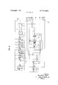
- FIG. 1 is a block diagram of the freight security system of the present invention.
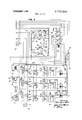
- FIG. 2 is a schematic drawing of a solid state transceiver, the switching mechanism for changing the transceiver from the receiving mode to the transmitting mode, the speaker, and the microphone being deleted.
- the interconnecting circuitry terminates at a plug which facilitates connecting the transceiver to the components schematically depicted in FIG. 3 or the components schematically depicted in FIG. 4.
- FIG. 3 is a schematic of the components peculiar to the equipment monitored by the security personnel.
- the interconnecting circuitry terminates at a plug which connects with the plug depicted in FIG. 2.
- FIG. 4 is a schematic of the components peculiar to the equipment which is intended to be planted in a freight package.
- the interconnecting circuitry terminates at a plug which is intended to be connected to the plug depicted in FIG. 2.
- the freight security system of the present invention is character referenced in FIG. 1 of the drawings by the numeral 11 and generally comprises at least one base transmitting and receiving station 13 and a plurality of portable solid state transponders 15 (one being shown in FIG. I). It should be understood that since each of the plurality of transponders are identical one with the other, it is considered expedient to depict a singular transponder for fully describing the system.
- the base station 13 generally comprises an activating apparatus 17 for initially activating a trigger circuit 19 which simultaneously triggers or causes to be energized a typical transmitter circuit 2] and a unique encoder circuit 23.
- the audio frequency output of the encoder 23 is modulated with the transmitting carrier frequency.
- the base station 13 also includes a typical receiver circuit 25 having a unique demodulated audio frequency output coupled to a plurality of decoder circuits 27, 29, 31.
- the system 11 preferably includes at least one decoder circuit for each transponder 15.
- the system ll preferably comprises numerous substantially identical decoder circuits, e.g., upwards of 50, and for expediency three are conveniently depicted to fully describe the system 11.
- the base station 13 additionally includes a plurality of amplifier circuits 33, 35, 37 which respectively respond to the decoder circuits 27, 29, 31 under prescribed circumstances yet to be disclosed.
- the outputs of the amplifiers 33, 35, 37 are coupled to respective relays 39, 41, 43 which, when energized, cause respective indicators 45, 47, 49, e. g., neon lights or the like, to be energized.
- the transponder 15 generally comprises a typical receiver circuit 51 for demodulating the encoded audio frequency which is coupled to a decoder circuit 53.
- the output from the decoder 53 is coupled to an amplifier circuit 55 and the output from the amplifier 55 is coupled to a trigger circuit 57.
- the transponder 15 also includes an encoder circuit 59 and a typical transmitter circuit 61, both of which are energized simultaneously by the trigger circuit 57.
- the following principle of operation will serve as a general overview for the system 11 of the present invention.
- the concept of the present invention is to plant a transponder 15 into a box of package 62 (a portion only being shown in FIG. 1) which is intended to be safe-guarded against theft while in transit and/or while sitting at a dock site.
- the system 11 will alert security personnel to the fact that this box 62 is being moved past a certain predetermined location.
- the transponder 15 includes a self-contained power supply and that the receiver 51 is placed in an "on" position when planted.
- the security system 11 of the present invention may be adapted to any conveyance means; however, in order to simplify the disclosure of the preferred embodiment, the trucking industry will herein be used as an example.
- the system is intended for operation on a frequency of 26.995 megacycles, which is designated Class C operation. Accordingly, the transmitters 21, 61 are tuned so as to have a carrier frequency 63 within this range. Obviously the receivers 25, 51 are also tuned to the carrier frequency 63 as above-described.
- the dock site (not shown) referably is provided with a guardhouse which houses the security personnel and the base station 13. All outgoing trucks (not shown) are funneled past a predetermined point which is provided with an elongated resilient tubular member 65, e. g., a rubber hose or the like, which terminates at the one end with a closure means, e.g., a plug or the like, and communicates at the other end with an enclosed bellows assembly 67.
- a closure means e.g., a plug or the like
- a terminal 71 is connected to a power source and closing the switch 69 activates the triggering circuit 19.
- the triggering circuit 19 can also be activated manually by the security personnel by closing a switch 73 which is physically located within the guardhouse, i.e., preferably on the cabinet structure (not shown) housing the electronic components.
- the trigger circuit simultaneously energizes the transmitter 21 and the encoder 23.
- the encoder 23 being an audio oscillator, oscillates at a very closely controlled audio frequency, e.g., 907.5 cycles per second, which modulates the carrier frequency 63.
- the receiver 51 thereof will demodulate the encoded audio frequency, e.g., 907.5 cps, which in turn is coupled to the decoder 53.
- the decoder 53 being tuned to accept or pass the frequency of 907.5, passes a signal on to the amplifier 55.
- the amplifier 55 increases the strength of the signal and activates the trigger circuit 57.
- the trigger circuit simultaneously energizes the encoder 59 and the transmitter 61.
- the encoder 59 modulates the carrier frequency 63 with a second very closely controlled audio frequency, e.g., 892.5 cycles per second, which is transmitted back to the base 13 and is received by the receiver 25.
- the receiver 25 demodulates the audio frequency 892.5 from the carrier frequency 63 and this audio output is connected to the plurality of decoders 27, 29, 31.
- a decoder 27 is tuned to a precise audio frequency, e.g., 862.5; the decoder 29 is tuned to a precise audio frequency, e.g., 877.5; and the decoder 31 is likewise tuned to a precise audio frequency, e. g., 892.5.
- each decoder preferably is tuned to its individually unique audio frequency.
- the audio output frequency 892.5 from the receiver 25 is simultaneously felt at the decoders 27, 29 and 31.
- the decoders 27, 29 reject this frequency, however, the decoder 31 accepts or passes the frequency to its individual amplifying circuit 37.
- the output from the amplifier 37 is coupled to the relay 43 which in turn energizes the neon light 49.
- the security personnel being familiar with the scheduled departure of the box 62 having the planted transceiver therein are alerted to the fact that the box in question is in fact on the truck being interrogated.
- the truck In the event the box is being legally transported, the truck merely moves on through the control point to its destination or to other interrogation stations 13.
- the interrogation stations 13 may be mobile so as to interrogate the truck in transit in accordance with detailed operating procedures peculiar to the conveyance means.
- the security personnel obviously take the appropriate corrective measures. These corrective measures alluded to may involve lengthy numerous detailed procedures and/or other mobile interrogators 13 for maintaining surveillance of the package containing the transponder 15, so as to apprehend other involved individuals, etc.
- the receiver 51 and the transmitter 61 may be two separate components, or they may be combined into a suitable single transceiver such as the Realistic Model No. TRC-45, which is a product of Radio Shack a division of Tandy Corporation.
- This transceiver is a two watt, ten transistor citizens band device and is schematically depicted in FIG. 2 of the drawings.
- FIG. 2 of the drawings substantially is a copy of the schematic contained in the Realistic Model No. TRC-45 catalog No. 21-130.
- the transmitter 21 and the receiver 25 of the base station 13 may be two separate components, or they too may be combined into a single transceiver similar to the Realistic THC-45, accordingly, a transceiver of the type schematically depicted in FIG. 2 is intended to be used at the base station 13 and a similar one with the transponder 15.
- the transceiver containing the transmitter 21 and the receiver 25 for the base 13 have a greater wattage output, e. g., 20 watts or the like.
- a greater wattage output e. g. 20 watts or the like.
- Numerous transceivers of varying tradenames and wattage outputs are commercially available, and the principle of operation is well known. Accordingly, a brief description of the transceiver depicted in FIG. 2 will suffice for present purposes and references should be made to the technical data provided by the manufacturer of the particular transceiver used for a more detailed description of the particular transceiver incorporated.
- FIG. 2 depicts a plug 75 having many contact pins, e. g., a cannon plug or the like, for expedience in disclosing the interconnecting circuitry between the respective FIGS. 2 and FIGS. 3 and 4.
- the plug 75 is optional and is used merely as a convenience in explaining the drawings.
- the above explanation obviously pertains to a plug 77 (FIG. 3) and a plug 79 (FIG. 4), i. e., the cannon plug 75 being a female type plug having structure suitable for receiving either of the two male type plugs 77, 79. Accordingly, the three plugs 75, 77, 79 will have identically numbered pins.
- Pin 81 carries the input signal to the receiver from the appropriate antenna.
- Pin 83 carries the output signal from the transmitter to the appropriate antenna. It should be understood that the general description of the receiver cannot conveniently be directed towards either the base station 13 or the transponder since the structure for the transceiver incorporated at the base station and the structure of the transceiver incorporated with the transponder are different; therefore, a detailed disclosure of the components peculiar to the base station 13 and the transponder 15 will subsequently be disclosed.
- Pin 85 carries the volume control feedback for the receiver.
- Pin 87 carries the power input for the receiver from the battery or other power supply.
- Pin 89 carries the power input to the final audio stages and/or the modulation stage of the transmit position from the battery or other power supply.
- Pin 91 carries B+ supply for transmitter 21.
- Pin 93 carries the receiver output;
- pin 95 carries the second conductor for the power input from the battery or other power supply.
- Pin 97 carries the encoder input signal or audio frequency to the transmitter.
- Pin 99 carries the second conductor from the battery for certain components while the transceiver is in the receiver mode.
- Pin 101 carries the second conductor from the battery or for various components while the transceiver is in the trasnmitting mode.
- the potentiometer 103 (FIG. 2), being the volume control for the receiver, varies the amplitude of the audio signal from the appropriate receiver, i.e., receiver 25 or receiver 51, to the respective decoder.
- the potentiometer 103 accordingly, provides the system 11 with a range control, i.e., enabling the base station 13 to adjust the range so that it is restricted to interrogating trucks within a predetermined radius.
- the radius referred to would obviously include a space which could conceivably be occupied by only one truck, thus precluding the likelihood of inadvertently interrogating two trucks simultaneously.
- FIG. 3 of the drawings wherein the components peculiar to the base station 13 and which are married to a transceiver such as depicted in FIG. 2, by connecting the plug 75 to the plug 77, are schematically illustrated.
- a power supply 105 preferably having a 12 volt direct current output is symbolized in the drawing as being a battery, however, the power supply 105 may be a 12 volt D. C. power supply derived from 115 volt alternating current in order to enhance reliability.
- a preferred arrangement wherein an emergency backup of a 12 volt battery which is automatically connected to the system 11 in the event of a power failure is advisable.
- the positive terminal of the power supply is grounded and leads to a single pole single throw master switch 107.
- Closing the switch 107 completes the circuit to a three-way junction which completes the circuit to: First, a push-button two-point "break" switch 109; secondly, a contact 111 of a four pole double throw relay 113; thirdly, pin 89 of the cannon plug 77. It should be understood that the numerous relay schematically depicted in the drawings are shown in a de-energized position.
- the negative side of the power supply 105 is connected to a negative bus bar 115.
- a conductor 117 connected at the one end of the bus bar leads to the two activating switches 69, 73.
- the switches 69, 73 are single pole single throw switches connected in parallel so that closure of either completes the circuit to a single pole double throw relay 119, a component of the trigger circuit 19.
- Energizing the relay 119 completes the circuit between the contacts 121, 123 which places the 12 volts on a 100 mfd capacitor 125, thus charging the capacitor 125.
- the activating switch i.e., either switch 69 or switch 73, is held in a closed position only momentarily and then returned to the open position.
- the relay 119 is energized briefly but sufficiently to charge the capacitor 125.
- the relay 119 being de-energized, returns to the normal position which completes the circuit between a contact 127 and the contact 123.
- the capacitor 125 having been charged, acts as a power supply and sends current through 15 K resistor 129 for a period of time selectively determined by the values chosen for the capaci tor and the resistor 125.
- a 15 K ohm resistor 131 is connected at the one end to the junction of the capacitor 125 and the resistor 129 and at the other end to the base 133 of a GE-2 transistor 135, the transistor 135 having the base 133, the emitter 137 and the collector 139.
- the voltage felt across the biasing resistor 131 on the base 133 causes the collector 139 to pull electrons from the emitter 137.
- the circuit for the abovementioned electron or current flow is through a conductor 141 having the one end thereof connected to the collector 139 and the other end connected to the winding of the relay 113, the other end of the winding 113 being connected to the negative bus bar 115.
- current flows from the power supply 105 through the transistor 135 and the relay 113, thus energizing the relay 1 13 for a predetermined period of time.
- the function of the relay 113 is to switch the base station 13 from a receiving mode to a transmitting mode and from the transmitting mode back to the receiving mode.
- the receiver 25 is normally on while the relay 113 is de-energized, and energizing the relay 113 turns on receiver off and activates the transmitter 21 for a predetermined period of time.
- This predetennined period of time is calculated by the values selected or the time constant of the capacitor 125 and the resistor 129. I prefer to have the transmitter activated for approximately five seconds before the relay 113 returns the base station 13 to the receiver mode.
- the relay 113 when in the receive mode, completes the circuit from a transmitting and receiving antenna 143 through a pair of contacts 145, 147, the contact 147 having one end of a conductor connected thereto, the other end of which is connected to the pin 81 of the plug 77. Secondly, the relay 113, when de-energized,
- the relay 113 delivers B+ from the power supply 105 to the pin 87 of the plug 77 through the aforementioned contact 111 and a contact 153.
- the deenergized relay 113 connects B of the power supply 105 to the pin 99 of the plug 77 through a pair of contacts 155, 157.
- the antenna 143 When the relay 113 is energized, i.e., the base station 13 being in the transmit mode, the antenna 143 is connected to the output of the transmitter through the pin 83 of the plug 77 and a pair of contacts 145, 159.
- the output of the encoder circuit 23 e.g., an audio frequency of 907.5 cycles per second, modulates the carrier frequency of the transmitter 21 by having one end of a conductor 160 connected to an output terminal 161 of the encoder circuit 23 and the other end connected to a contact 163 of the relay 113, a second conductor 162 completes the circuit from the contact 149 to the pin 97 of the plug 77.
- 13+ is applied to a positive bus bar 165 of the encoder circuit 23 by having one end of a conductor 166 connected thereto and the other end being connected to a contact 167 of the relay 113, i. e., the contact 111 being connected to 8+ as previously described.
- the negative bus bar 115 is connected to the pin 101 of the plug 77 through a contact 169 of the relay 1 13, i. e., the contact 155 being connected to the bus bar 115 as previously described.
- the heart of the encoder circuit 23 is a subminiature piezoelectric tuning fork 171 manufactured under the tradename of Microfork" which is manufactured by the Murato Manufacturing Co., Ltd., of 160 Broadway, N.Y., NY.
- the microfork used in the present invention for the encoder is a model EFM and is a newly designed tuning fork subminiaturized from Pieleforks. This model is now widely used for bellboy systems, selective calling, remote control and tone control of electronic musical instruments where compactness, reggedness and economy are required.
- the microfork 171 having a length slightly greater than one inch and transversal dimensions of less than one-third inch, operates in the frequency range of 360 2,900 cps with an accuracy of 0.5 cps up to 999 cps and 1 cps from 1,000 2,900 cps.
- the encoder circuit 23 is substantially identical with the test circuit included in the technical data provided by the Murata Manufacturing Co. pertaining to the microfork 171.
- the microfork 171 has three predetermined terminals P, S and G, i.e., the preferred connection is:
- the terminal P is the output terminal;
- the terminal S is the input terminal; and
- the terminal G is the ground terminal.
- the encoder circuit 23 includes: (1) A negative bus bar 173, connected by a conductor 174, to the power supply negative bus bar 115.
- the capacitor 175 has one side thereof connected to the positive bus bar 165 and the other side connected to the input terminal of the microfork 171, i.
- a 10 K ohm resistor 189 having one end thereof connected to the output terminal 161 of the encoder circuit 23 and the other end connected to the positive bus bar 165.
- a l K ohm resistor 19] having one end thereof connected to the output terminal 161 and the other end connected to the one end of a 10 mfd capacitor 193.
- a 33 K ohm resistor having one end thereof connected to the negative bus bar 173 and the other end connected to a common point 196.
- a 4.7 K ohm resistor 197 having one end thereof connected to the common point 196 and the other end connected to the positive bus bar 165.
- the other end of the capacitor 193 is connected to a point between the junction of the resistors 195, or in essence the common point 196.
- a second GE-Z transistor 199 having a base 201, an emitter 203 and a collector 205, has the base thereof 20] connected to the common point 196, the collector 205 connected to a common point 207, and the emitter 203 connected to a common point 209.
- a 5.6 K ohm resistor 21 1 has one end thereof connected to the common point 207 and the other end connected to the negative bus bar 173.
- a conductor 213 has one end thereof connected to the common point 207 and the other end connected to the P terminal or the output terminal of the microfork 171.
- a l K ohm resistor 215 has one end thereof connected to the common point 209 and the other end connected to the positive bus bar 165.
- a 10 mfd capacitor 217 has one end thereof connected to the common point 209 and the other end connected to the positive bus bar 165.
- the above network of electronic components comprises an audio oscillator or encoder circuit 23 having a closely controlled frequency output, e.g., 907.5 cps i 0.5 cps.
- the carrier frequency 63 is modulated with this frequency, i. e., 907.5 cps, when the relay 113 is energized, as above-described.
- a 0.0047 mfd capacitor 219 having the one end thereof connected to the nega' tive bus bar 173 and the other end connected to the positive bus bar 165, is optional and is used herein to electrically isolate the transmitter 21 and receiver 25 (FIG. 2), having a negative ground, from the circuitry schematically depicted in FIG. 3 which has a positive ground.
- the base station 13 sending a coded signal, i. e., 907.5 cps, from the transmitter 21 to the antenna 143.
- the carrier frequency 63 radiates outwardly from the antenna 143 in all directions and assuming that a truck (not shown) having a carton 62 containing the planted transponder 15 therein is physically located at the interrogation point, the receiver 51 of the transponder 15 will receive the transmission.
- the receiver 51 detects of demodulates the coded signal, i.e., 907.5 cps, which is delivered to the pin 93 of the plug 75 (FIG. 2).
- a conductor 220 having one end thereof connected to the pin 93 of the plug 79 and the other end connected to the primary windings of a step up transformer 221, carries the output from the receiver 51. It should be pointed out that normally the output of a receiver is delivered to a step down transformer which steps up the current sufficiently to drive the speaker element. The current requirements for the embodiment of the present invention are minimum; however, the voltage or amplitude of the signal is stepped up across the transformer 221.
- a conductor 222 having the one end thereof connected to the primary of the transformer 221 and the other end connected to a common point 223, completes the circuit for the input signal, i.e., the common point 223, having a B- potential yet to be described, is connected to the pin 95 of the plug 77.
- the transponder has a transmitting and/or receiving antenna 225 and a four pole double throw relay 227 having a function substantially identical to the relay 113 for the base station 13, above-described.
- the relay 227 when de-energized, places the transponder 15 in the receiver mode by connecting the antenna 225 to the receiver 51 through a pair of contacts 229, 231, i.e., a conductor connecting the antenna 225 to the contact 229 and a second conductor connecting the second contact 231 to the pin 81 of the plug 79.
- the pins 85, 97 of the plug 79 are connected by a pair of contacts 233, 235, i.e., a conductor connects the pin 97 to the contact 233 and a second conductor connects the pin 85 to the contact 235.
- the pin 87 is connected to a 8+ potential, yet to be described, by a pair of contacts 237, 239, i.e., a conductor connects the pin 87 to the contact 239 and a second conductor connects a common point 240 to the contact 237.
- 8+ is applied to the common point 240 by having the one end of a conductor 242 connected to 8+ and the other end thereof connected to the common point 240.
- the transponder 15 includes a power supply 241, e.g., preferably a 12 volt battery or ten individual cells connected in series so as to deliver 12 volts direct current.
- the positive side or B+ of the power supply 241 leads to a master "on or off" switch 243 which applies 8+ to the above-mentioned common point 240. It should be observed that the positive side of the power supply 241 is grounded.
- the negative side or B of the power supply 241 is connected to a negative bus bar 245 and a conductor 246 connects the above-mentioned common point 223 to the bus bar 245.
- a pair of contacts 247, 249 completes the circuit between the negative bus bar 245 and pin 99, i.e., a conductor 250 connects the bus bar 245 and the contact 247 and a conductor 252 connects the pin 99 and the contact 249.
- the transponder 15 is placed in the transmitting mode when the relay 227 is energized.
- Energizing the relay 227 first places the output from the transmitter 61 to the pin 83 of the plug 79.
- the pin 83 is connected to the antenna 225 by a contact 251 and the contact 229, i.e., a conductor connects the pin 83 to the contact 25].
- the pin 97 is connected to an output terminal 253 of the encoder circuit 59, i.e., a conductor 254 connects the output terminal 253 to a contact 255 of the relay 227.
- a common point 257 is connected to 8+ of the power supply 241 by a contact 259, i.e., a conductor connects the contact 259 to the common point 257, the contact 249 being tied to 8+ as previously described.
- a contact 261 connects the negative bus bar 245 or B- to th pin 101 of the plug 79, i.e., a conductor connects the contact 261 to the pin 10] and the conductor 250 having the one end thereof connected to the contact 247 is con nected at the other end to the bus bar 245 as previously described.
- the output, i.e., 907.5 cps, of the receiver 51 was placed on the primary winding of the transformer 221, the relay 227 being de-energized.
- One end of the secondary winding of the transformer 221 is connected to the P or output terminal of a receiving type microfork 263.
- the microfork model RPM is provided by the Murata Manufacturing Co. in two separate configurations: a transmitter or sender type microfork designated EFM-S and a receiver type, for responding to or passing a narrow width of audio frequencies, designated EFM-R.
- EFM-S transmitter or sender type microfork
- EFM-R a receiver type
- the previously described specifications for microforks are directed to both the EFM-R and the EFM-S types.
- the other end of the secondary winding of the transformer 221 is void of the usual ground connection, i.e., having interelectrode capacitance only or in other words the circuit for the secondary is open which allows the voltage from the secondary to be felt at the terminal P but does not permit current flow through the microfork 263.
- the microfork 263, as above described, is manufactured or fixed to be responsive to a predetermined narrow band of audio frequencies and to reject all other frequencies. Since the base station 13 is transmitting a carrier frequency 63 which is modulated by the encoder 23 with an assumed frequency of 907.5 cps i 0.5 cps, the microfork 263 must be selected to be responsive to the assumed frequency of 907.5 cps.
- the narrow band width of frequencies which the microfork 263 will respond to is approximately 902 cps 1,002 cps, i.e., the microfork 263 will reject any other frequency.
- the G terminal of the microfork 263 is connected to ground, and assuming that the incoming frequency was within the above-specified range, the microfork will pass a minute signal from the S terminal to the audio amplifying circuit 55.
- the first stage of the audio amplifying circuit 55 comprises: (1) A (IE-2 transistor 265, having the usual base 267, the collector 269, and the emitter 271.
- the minute signal from the microfork 263 is coupled to the base 267.
- the collector 269 of the transistor 265 is also connected to the common point 289.
- a 10 K ohm bias resistor 291 has the one end thereof connected to ground, and the other end connected to a common point 293.
- the emitter 271 of the transistor 265 is also connected to the common point 293.
- the amplified output of this first stage is coupled to a second amplifying stage by a 10 mfd electrolytic capacitor 295.
- the second amplifying stage comprises: (1 A second GE-Z transistor 297, having the usual base 299, a collector 301, and an emitter 303, The base 299 of the transistor 297 is connected to a common point 305.
- the coupling capacitor 295 has one end thereof connected to the common point 293 and the other end connected to the common point 305 which places the amplified signal of the first stage onto the base 299 of the second stage transistor 297.
- a 15 K ohm resistor 307 and a 39 K ohm resistor 309 comprise a voltage divider network by having the one end of the resistor 309 connected to the common point 285 and the other end connected to the common point 305, also, the one end of the resistor 307 being connected to the common point 305 and the other end thereof being connected to ground.
- a 4.7 K ohm biasing resistor 311 having one end thereof connected to the common point 281 and the other end being connected to the collector 301 of the transistor 297.
- a mfd electrolytic capacitor 315 connected in parallel with the resistor 313, i.e., the one end of the capacitor 315 being connected to one end of the resistor 313, and the other end thereof being connected to ground.
- the capacitor 315 is a bypass capacitor, i.e., prevents the signal from going to ground.
- a 10 mfd electrolytic capacitor 317 couples the output signal from the second stage of the amplifier circuit 55 to a rectifier circuit 319, comprising a pair of 1 N 34 diodes 321, 323.
- the diode 321 has the usual anode 325 and cathode 327 and the diode 323 has the usual anode 329 and the cathode 331.
- the anode 325 is connected to the cathode 331 at a common point 333, the cathode 327 is connected to ground, and the anode 329 is connected to a second common point 335.
- the coupling capacitor 317 has the one end thereof connected to the collector 301 of the transistor 297 and the other end connected to the common point 333.
- a coupling means 337 couples the rectified output of the rectifier 319 to the triggering circuit 57.
- the coupling means 337 comprises: l) A GE-2 transistor 339, having the usual base 341, the collector 343, and the emitter 345. (2) A 22 K ohm biasing resistor 347. (3) A ll) mfd electrolytic capacitor 349. The one end of the resistor 347 is connected to the common point 335 and the other end is connected to ground.
- the filtering capacitor 349 filters the signal onto the transistor 339, i.e., the signal now being a steady substantially DC voltage. The one end of the capacitor 349 is connected to a point having the same potential as does the common point 335 and the other end of the capacitor 349 is connected to ground.
- the base 341 is connected to this point, i.e., having the same potential as does the common point 335.
- the coupling means 337 also includes a 68 ohm biasing resistor 351 having the one end thereof connected to the emitter 345 and the other end connected to ground.
- This signal or steady DC voltage being applied to the base 341 of the transistor 339 causes current to flow from the emitter 345 to the collector 343, i.e., the path of current flow being through the resistor 351 to ground. Thence the current flows to the positive side of the power supply 241, thence through the power supply or out the negative bus bar 245 through the conductor 275 to the common point 277, thence through a conductor 353 past a common point 355 to one end of the winding of a single pole double throw relay 357, thence out the other side of the relay 357 through a conductor 359 to the collector 343, i.e., the relay 357 being a part of the trigger circuit 57.
- the relay 357 is energized, which charges a 250 mfd electrolytic capacitor 361, i.e., the circuit being completed through a pair of contacts 363, 365, the contact 363 being at the same potential as the common point 355 or having a negative l2 volt potential, thence through a conductor 367 which connects one end of the capacitor 361 to the contact 356 thence through a conductor 369 which connects the other end of the capacitor 361 to ground, thence from ground to the positive side of the power supply 241, all being additional components of the trigger circuit 57.
- a 250 mfd electrolytic capacitor 361 i.e., the circuit being completed through a pair of contacts 363, 365, the contact 363 being at the same potential as the common point 355 or having a negative l2 volt potential
- the relay 357 will remain energized so long as the transistor 339 feels the constant voltage from the filtering circuit 319; howver, the base station 13 triggering circuit 19 preferably is programmed so as to key the transmitter 21 and trigger the encoder 23 for a duration of 5 seconds, after which time it goes back to the receive mode.
- the output of the receiver 51 of the transponder 15 will also have a duration If 5 seconds, after which time the signal across the transformer 221 ceases since the voltage felt on the microfork 263 is nil, thence the input to the amplifier circuit 55 is nil, thence the input to the filtering network 319 is nil which causes current to cease flowing from the emitter 345 to the collector 343 of the transistor 339 which de-energizes the relay 357 after the 5 second duration.
- the charged capacitor 361 acting as a power source, starts to discharge through the conductor 367, thence from the contact 365 to a third contact 371, thence through a conductor 373, having the one end thereof connected to the contact 371 and the other end connected to a common point 375, thence through an K ohm resistor 377, having one end thereof connected to the common point 375 and the other end connected to ground, thence through the conductor 369 to the other side of the capacitor 361, all being further components of the trigger circuit 57. Accordingly, the common point 375 assumes a negative potential equal to the charge on the capacitor 361.
- the triggering circuit 57 also includes a GE-2 transistor 379, having the usual base 381, the collector 383, and the emitter 385, and a 15 K ohm bias resistor 387.
- the voltage at the common point 375, being biased by the bias resistor 387 is felt on the base 381 of the transistor 379 which causes current flow through the transistor 379, i.e., the path of current flow being from the emitter 385 down through a conductor 389 to ground, thence to the positive side of the power supply 241, thence out the negative bus bar 245 through a conductor 391, having one end thereof connected to the negative bus bar 245 and the other end connected to the relay 227, thence through the winding of the relay 227, thence through a conductor 395, having one end thereof connected to the relay 227 and the other end connected to the collector 383.
- the relay 227 is energized while the capacitor 361 is discharging, i.e., the period of time being selectively determined by the values chosen for the capacitor 361 and the resistor 377.
- the preferred period of time for the relay 227 to remain energized is 15 seconds. it should be understood that it may be desirable in other embodiments to have the relay 227 energized for other periods of time which are considered to be within the full intended scope and spirit of the present invention.
- Energizing the relay 227 deactivates the receiver 51 and simultaneously keys the transmitter 61 and triggers the encoder 59, i.e., the contacts 229, 251 place the antenna 225 in communication with the pin 83 of the plug 79, the contacts 233, 255 place the output terminal 253 of the encoder 59 in communication with the pin 97, the contacts 237, 259 places the positive side of the power source 241 or 8+ on the common point 257 (the common point 257 communicating with the pin 91 and a positive bus bar 397 of the encoder circuit 59), and the contacts 247, 261 place the negative bus bar 245 in communication with the pin 101.
- the transmitter 61 commences transmitting the carrier frequency 63 and the encoder 59, having the bus bar 397 energized, commences oscillating at a predetermined audio frequency which is modulated or mixed with the carrier frequency 63.
- the audio frequency of the encoder 59 is determined and closely controlled or stabilized by a subminiature piezoelectric tuning fork, e.g., a microfork Model EFM-S 399.
- a subminiature piezoelectric tuning fork e.g., a microfork Model EFM-S 399.
- the microfork 171 for the encoder 23 and the microfork 263 for the decoder 53 are always tuned to the same frequency, e. g., 907.5 cps, irrespectively of the number of transponders 15 incorporated with the system 11.
- each transponder 15 will have its unique encoder 59 frequency, e. g., 892.5 cps, and the base station 13 will have a decoder circuit tuned to that unique frequency, e.g., the decoder 31 as previously described.
- the microfork 399 is tuned to the frequency peculiar to the specific transponder 15, in this case 892.5 cps.
- the encoder circuit 59 (FIG. 4) is identical to the encoder circuit 23 (FIG. 3), i.e., the frequency of the microfork 399 differs from that of the microfork 171, but the respective interconnecting circuits and values of their components are identical. Accordingly, the previous detailed disclosure of the encoder 23 is intended to encompass the encoder S9.
- the output of the encoder 59 leaves the encoder 59 from the output terminal 253 through the conductor 254, havine one end thereof attached to the terminal 253 and the other end connected to the contact 255, and enters the transmitter 61 through the pin 97 of the plugs 75, 79 where it modulates the carrier frequency 63.
- the base station 13 receives this carrier frequency 63 on the receiver 25 which detects or demodulates the encoder frequency, i.e., 892.5 cps, and this signal is placed on the pin 93 of the plugs 75, 77 (FIGS. 2 and 3).
- the relay 113 is in the deenergized position, the incoming signal from the receiver 25 is between the pins 93, 95 of the plug 77 which are in communication with the primary windings of a step-up transformer 403, e.g., having a ratio of 50 1.
- the decoder 27 comprising a subminiature piezoelectric receiving" tuning fork 405, e.g., microfork model EF- M-R
- the decoder 29 comprising a subminiature piezoelectric receiving" tuning fork 407, e.g., a microfork model EFM-R
- the decoder 31 comprising a subminiature piezoelectric "receiving tuning fork 409
- microforks 405, 407, 409 are in parallel one with the other, i.e., the P or output terminal of each is connected to a common point which is in communication with the secondary of the transformer 403 and the G or ground terminal of each is connected to ground.
- the S or input terminals of the respective microforks 405, 407, 409 are connected to the amplifier circuits 33, 35, 37.
- the amplifier circuits 33, 35, 37 are individually identical to the amplifier circuit 55 (F IG. 4) previously described. Consequently, the detailed disclosure of the amplifier circuit 55 is intended to encompass the amplifier circuits 33, 35, 37, i.e., the value of the components and the interconnecting circuitry are identical.
- the respective outputs from the amplifiers 33, 35, 37 are coupled to a plurality of rectifier circuits 411, 413, 415.
- the rectifier circuits 411, 413, 415 are individually identical to the rectifier circuit 319 (FIG. 4). Consequently, the detailed disclosure pertaining to the rectifier circuit 319 is intended to encompass the rectifier circuits 411, 413, 415, additionally, the respective coupling capacitors 317, 317', 317", 317" are identical one with the other.
- the output of the respective rectifier circuits 411, 413, 415 are coupled to the relays 39, 41, 43 by a plurality of coupling means 417, 419, 421.
- the coupling means 417, 419, 421 are individually identical to the coupling means 337 (FIG. 4). Consequently, the detailed disclosure pertaining to the coupling means 337 is intended to encompass the plurality of coupling means 417, 419, 421.
- the relays 39, 41, 43 being identical one with the other, are double pole single throw holding relays for respectively energizing the plurality of indicator means, e. g., the neon lights 45, 47, 49. Accordingly, a detailed description of each relay 39, 41, 43 would be redundant.
- the microfork 409 is pretuned at the factory to the frequency of 892.5 cps and will pass a frequency within 5 cps of this frequency and reject all others.
- the microforks 405, 407 are respectively tuned to a fixed frequency of 862.5 cps and 877.5 cps and will pass frequencies within 5 cps of these fixed frequencies and will reject all other frequencies.
- the signal i. e., 892.5 cps from the transformer 403, is simultaneously felt at the microforks 405, 407 and 409.
- the microforks 405, 407 reject this signal; however, the microfork 409 accepts or passes the signal to the S or input terminal.
- This signal is received by the two stage audio amplifier circuit 37 which passes it through the coupling capacitor 317" to the filtering circuit 415.
- the filtered signal i. e., a substantially steady DC voltage, is coupled to the relay 43 by the coupling means 421, a conductor 359" carrying the positive gate type signal to the relay 43.
- the relay 43 is energized, completing the circuit between the contacts 423, 425, 427, 429 thereof.
- the one side of the winding of the relay 43 and one side of the neon light 49 are both tied to the negative bus bar 115.
- the contacts 427, 423 are connected to the switch 109 which is connected to the positive side of the power supply 105.
- Energizing the relay 43 momentarily, e. g., 15 seconds or the like, causes the contacts 423, 425 to complete the circuit from the positive side of the power supply to the winding of the relay 43, thus holding the relay 43 in an energized position until it is manually deenergized by pushing the pushbutton switch 109.
- the circuit is complete across the contacts 427, 429 which places the positive side of the power supply on the other side of the neon light 49, thus causing it to be energized until the switch 109 is manually pushed.
- the illumination of the neon light 49 alerts the security personnel to the fact that the package containing the transponder 15 is in the fact in the truck or other means of conveyance being interrogated.
- the neon lights 45, 47 are for other transponders 15 which may have been planted in other cartons.
- the base station 13 would include numerous neon lights (not shown) for safe-guarding a like number of cartons, e. g., 50 or more,
- An electronic freight security system comprising means positioned at a first location for receiving radio frequency signals, means positioned at said first location for transmitting radio frequency signals, encoder means positioned at said first location for modulating said transmitting means with a first narrow band width predetermined fixed signal, means positioned at said first location for simultaneously triggering said transmitting and said encoder means, means positioned at a location remote from said first location for receiving radio frequency signals, means positioned at said remote location for transmitting radio signals, decoder means positioned at said remote location for responding to said first signal and for passing a narrow width of predetermined frequencies, means positioned at said remote location for amplifying said passed frequencies, encoder means positioned at said remote location for modulating said transmitting means at said remote location with a second narrow band width predetermined fixed signal having a frequency different from said first signal, means positioned at said remote location for discriminatively triggering simultaneously said transmitting means and said encoder means thus causing said remote transmitting means to operate only when said decoder means responds to a signal transmitted from said first location, decoder means
- said activating means includes a bellows actuated switching means, and an elongated resilient tubular member containing a captured quantity of fluid which is communicated with said switching means for displacing said bellows thereof when said resilient member is squeezably compressed so as to close said switching means.
- An electronic freight security system for remotely monitoring the physical location of a plurality of freight packages while in transit or while at a dock site comprising means positioned at a first location for receiving radio frequency signals, means positioned at said first location for transmitting radio frequency signals, encoding means positioned at said first location for modu lating said transmitting means with a first narrow band width predetermined fixed audio signal, means positioned at said first location for simultaneously triggering said transmitting means and said encoder means, means positioned in a plurality of packages at a plurality of locations which are remote from said first location for receiving radio frequency signals, means positioned in each of said packages for transmitting radio signals, decoder means positioned in each of said packages for respectively responding to said first signal and for passing a narrow width of predetermined frequencies, means positioned in each of said packages for respectively amplifying said passed frequencies, encoder means positioned in each of said packages for respectively modulating said transmitting means with a plurality of audio signals of predetermined unique frequen cies, means positioned in said packages for respectively triggering said transmit
Abstract
An electronic security system for safe-guarding freight against theft while in transit and/or while sitting at a dock site. The concept of the system is to plant a unique transceiver in the freight package which responds with a coded signal when properly interrogated, i. e., with a coded radio frequency. The system includes a second transceiver, which is monitored by security personnel, and which is positioned at a strategic location. The monitored transceiver may be automatically triggered each time a conveyance means, e. g., a truck or the like, passes a particular point or it may be triggered manually. Triggering the monitored transceiver causes the transmitted carrier frequency to be modulated with a first coded audio signal. The planted transceiver responds with a second coded signal, if the first signal was of the proper frequency. The monitored transceiver includes a plurality of decoding networks and a plurality of neon lights which respectively respond to signals accepted by the decoding networks. Each light and associated decoding network monitors a separate freight package for purposes of alerting the security personnel when unauthorized movement of the freight package is occurring. The system has the capability of simultaneously safe-guarding numerous packages, e. g., 50 or more, positioned at one location. Additionally, the system is capable of discriminating or pinpointing the particular conveyance means that is carrying the freight package.
Description
United States Patent Smith Nov. 13, 1973 FREIGHT SECURITY SYSTEM against theft while in transit and/or while sitting at a [75] Inventor; William van Smith, Memphis, dock site. The concept of the system is to plant a Ten unique transceiver 1n the freight package which responds with a coded signal when properly interro- [73] Assignee: Lectrolarm Custom Systems, Inc., gated with a coded {adio l i l system Memphis Tenn. includes a second transce ver, WhIC h IS monitored by security personnel, and which is positioned at a strate- [22] Filed: Dec. 29, 1971 gic location. The monitored transceiver may be automatically triggered each time a conveyance means, e.
Appl' 213703 g., a truck or the like, passes a particular point or it may be triggered manually. Triggering the monitored [52] U.S. Cl 340/224, 325/8, 340/38 R, transceiver causes the transmitted carrier frequency to 340/152 T, 340/171 PF, 340/258 R, be modulated with a first coded audio signal. The
340/3l2, 343/65 SS planted transceiver responds with a second coded sig- [51] Int. Cl. GOls 1/02 nal. if the first signal was of the proper frequency. The [58] Field of Search 340/152 T, 38 R, monitored transceiver includes a plurality of decoding 340/38 L, 224, 309.1, 152 T, 17] PF; networks and a plurality of neon lights which respec 343/65 SS; 325/8 tively respond to signals accepted by the decoding networks. Each light and associated decoding network [56] References Cited monitors a separate freight package for purposes of UNITED STATES PATENTS alerting the security personnel when unauthorized 3 58] 283 5/1971 Rcddeletal 340", PF movement of the freight package is occurring. The 3005:1585 12/1972 Batz 325/8 x system has the capabilty of Simultaneously safe 293,642 12/1966 Gieles 343/65 ss guarding numerous Packages 50 Posi- 3,060,406 10/1962 wright H 340/38 R x tioned at one location. Additionally, the system is ca- 2,979,706 4/1961 Simon et al 340/224 Pable Of discriminating or pinpointing the Particular 3,054,100 9/1962 Jones 34316.5 SS conveyance means that is carrying the freight pack- Primary ExaminerDavid L. Trafton Attorney-John R. Walker, ll]
[57] ABSTRACT An electronic security system for safe-guarding freight RECEIVER l W TRANSM/TIER l 1 //7 l age.
3 Claims, 4 Drawing Figures 0560051? i DECOOEI? I 056005]? I T7911 0 [Ti/T1 AMP l as l g l as l [RELAY [RELAY RELAY 1 L- 1 @45 E 4? L ws 1 1 '5 T 1 T l m RECEIVER 1 l 1 1 1 W M i i W 25 i i if J PAIENTEU nnv 13 1913 SHEET 1 BF 4 ib E mwimumm L INVENTOR. WILL/AM V. SMITH r kmbbkfi at a 3.772.668 SHEET 2 BF 4 INVEN TOR.
\ w z a PMENTEDHUV 13 I973 PAIENIEUuuv I 3 ms SHEET 3 CF 4 FIG. 3
l Q "mo T INVENTOR. WILL/AM V. SMITH FREIGHT SECURITY SYSTEM BACKGROUND OF THE INVENTION 1. Field of the Invention This invention relates to two-way electronic communications systems for use with security systems, particularly safe-guarding freight against theft while in transit.
A problem of increasing magnitude prevails in the field of transportation wherein certain packages of freight are stolen from the dock site, or the like, particularly high value items. The problem has many facets, e.g., frieght handlers having unscrupulous characters colluding with truck drives of bona tide agencies having legitimate business at the dock site place the highvalued commodity onto the truck where it may be transported to an assembly point for receiving the stolen property. The obvious solution to the abovementioned problem is to simply place an armed guard with the package so that it may be under constant surveillance by security personnel. This solution is costly in manhours. Additionally, a cunningly planned scheme could Conceivably involve nullifying the guards efiectiveness by inducing bodily harm or the like. However, the usual practice is for the unscrupulous personnel to concentrate their efforts on the packages which are not under surveillance.
SUMMARY OF THE INVENTION The present invention is directed towards overcoming the abovementioned problem. Solving the problem would be greatly simplified by simply placing a transmitter in the package which continuously is transmitting a radio signal. This radio signal could be monitored by a receiver, thus constantly providing adequate surveillance for the freight package. However, constantly operating a transmitter with sufficient output wattage to pass through the truck strucure, etc., requires power in excess of feasible present day sources. On the other hand, with the use of the present invention, the receivers therein utilizing present day equipment, e.g., solid state electronics transceivers or the like, can be continuously operated over a long period of time, i.e., commensurate with realistic shipping schedules.
Implementation of the freight security system of the present invention provides the security personnel with a positive means of providing electronic surveillance of the particular freight package. The concept of the present invention is to plant a unique transceiver in the freight package which responds with a coded signal when properly interrogated, i.e., with a coded radio frequency. The system includes a second transceiver which is monitored by security personnel, and which is positioned at a strategic location. The monitored transceiver may be automatically triggered each time a conveyance means, e.g., a truck or the like, passes a particular point or it may be triggered manually. Triggering the monitored transceiver causes the transmitted carrier frequency to be modulated with a first coded audio signal. The planted transceiver responds with a second coded signal, if the first signal was of the proper frequency. The monitored transceiver includes a plurality of decoding networks and a plurality of neon lights which respectively respond to signals accepted by the decoding networks. Each light and associated decoding network monitors a separate freight package for purposes of alerting the security personnel when unauthorized movement of the freight package is occurring.
The system has the capability of simultaneously safe guarding numerous packages, e.g., or more, positioned at one location. Additionally, the system is capa ble of discriminating or pinpointing the particular conveyance means that is carrying the freight package.
BRIEF DESCRIPTION OF THE DRAWINGS FIG. 1 is a block diagram of the freight security system of the present invention.
FIG. 2 is a schematic drawing of a solid state transceiver, the switching mechanism for changing the transceiver from the receiving mode to the transmitting mode, the speaker, and the microphone being deleted. The interconnecting circuitry terminates at a plug which facilitates connecting the transceiver to the components schematically depicted in FIG. 3 or the components schematically depicted in FIG. 4.
FIG. 3 is a schematic of the components peculiar to the equipment monitored by the security personnel. The interconnecting circuitry terminates at a plug which connects with the plug depicted in FIG. 2.
FIG. 4 is a schematic of the components peculiar to the equipment which is intended to be planted in a freight package. The interconnecting circuitry terminates at a plug which is intended to be connected to the plug depicted in FIG. 2.
DESCRIPTION OF THE PREFERRED EMBODIMENT The freight security system of the present invention is character referenced in FIG. 1 of the drawings by the numeral 11 and generally comprises at least one base transmitting and receiving station 13 and a plurality of portable solid state transponders 15 (one being shown in FIG. I). It should be understood that since each of the plurality of transponders are identical one with the other, it is considered expedient to depict a singular transponder for fully describing the system.
The base station 13 generally comprises an activating apparatus 17 for initially activating a trigger circuit 19 which simultaneously triggers or causes to be energized a typical transmitter circuit 2] and a unique encoder circuit 23. The audio frequency output of the encoder 23 is modulated with the transmitting carrier frequency. The base station 13 also includes a typical receiver circuit 25 having a unique demodulated audio frequency output coupled to a plurality of decoder circuits 27, 29, 31. It should be pointed out that the system 11 preferably includes at least one decoder circuit for each transponder 15. In this regard, the system ll preferably comprises numerous substantially identical decoder circuits, e.g., upwards of 50, and for expediency three are conveniently depicted to fully describe the system 11.
The base station 13 additionally includes a plurality of amplifier circuits 33, 35, 37 which respectively respond to the decoder circuits 27, 29, 31 under prescribed circumstances yet to be disclosed. The outputs of the amplifiers 33, 35, 37 are coupled to respective relays 39, 41, 43 which, when energized, cause respective indicators 45, 47, 49, e. g., neon lights or the like, to be energized.
The transponder 15 generally comprises a typical receiver circuit 51 for demodulating the encoded audio frequency which is coupled to a decoder circuit 53. The output from the decoder 53 is coupled to an amplifier circuit 55 and the output from the amplifier 55 is coupled to a trigger circuit 57. The transponder 15 also includes an encoder circuit 59 and a typical transmitter circuit 61, both of which are energized simultaneously by the trigger circuit 57.
Referring still to FIG. 1 of the drawings, the following principle of operation will serve as a general overview for the system 11 of the present invention. The concept of the present invention is to plant a transponder 15 into a box of package 62 (a portion only being shown in FIG. 1) which is intended to be safe-guarded against theft while in transit and/or while sitting at a dock site. The system 11 will alert security personnel to the fact that this box 62 is being moved past a certain predetermined location. lt should be understood that the transponder 15 includes a self-contained power supply and that the receiver 51 is placed in an "on" position when planted. It should be further understood that the security system 11 of the present invention may be adapted to any conveyance means; however, in order to simplify the disclosure of the preferred embodiment, the trucking industry will herein be used as an example. The system is intended for operation on a frequency of 26.995 megacycles, which is designated Class C operation. Accordingly, the transmitters 21, 61 are tuned so as to have a carrier frequency 63 within this range. Obviously the receivers 25, 51 are also tuned to the carrier frequency 63 as above-described. There are numerous operational procedures and/or physical layouts for implementing the system 11 of the present invention. Accordingly, the following disclosure is intended to be one example:
The dock site (not shown) referably is provided with a guardhouse which houses the security personnel and the base station 13. All outgoing trucks (not shown) are funneled past a predetermined point which is provided with an elongated resilient tubular member 65, e. g., a rubber hose or the like, which terminates at the one end with a closure means, e.g., a plug or the like, and communicates at the other end with an enclosed bellows assembly 67. When the truck passes over the air hose 65, the captured air displaces the bellows assembly 67, closing the switch 69.
A terminal 71 is connected to a power source and closing the switch 69 activates the triggering circuit 19. The triggering circuit 19 can also be activated manually by the security personnel by closing a switch 73 which is physically located within the guardhouse, i.e., preferably on the cabinet structure (not shown) housing the electronic components. The trigger circuit simultaneously energizes the transmitter 21 and the encoder 23. The encoder 23 being an audio oscillator, oscillates at a very closely controlled audio frequency, e.g., 907.5 cycles per second, which modulates the carrier frequency 63.
[n the event the truck which caused the activating apparatus 17 to operate does not contain the package having the transponder 15 planted therein, the sequence is thusly terminated.
However, in the event the truck which caused the activating apparatus 17 to operate is carrying the package having the transponder 15 planted therein, the receiver 51 thereof will demodulate the encoded audio frequency, e.g., 907.5 cps, which in turn is coupled to the decoder 53. The decoder 53, being tuned to accept or pass the frequency of 907.5, passes a signal on to the amplifier 55. The amplifier 55 increases the strength of the signal and activates the trigger circuit 57. The trigger circuit simultaneously energizes the encoder 59 and the transmitter 61. The encoder 59 modulates the carrier frequency 63 with a second very closely controlled audio frequency, e.g., 892.5 cycles per second, which is transmitted back to the base 13 and is received by the receiver 25.
The receiver 25 demodulates the audio frequency 892.5 from the carrier frequency 63 and this audio output is connected to the plurality of decoders 27, 29, 31. A decoder 27 is tuned to a precise audio frequency, e.g., 862.5; the decoder 29 is tuned to a precise audio frequency, e.g., 877.5; and the decoder 31 is likewise tuned to a precise audio frequency, e. g., 892.5. In other words, regardless of the number of decoders contained in the system 11, each decoder preferably is tuned to its individually unique audio frequency. The audio output frequency 892.5 from the receiver 25 is simultaneously felt at the decoders 27, 29 and 31. The decoders 27, 29 reject this frequency, however, the decoder 31 accepts or passes the frequency to its individual amplifying circuit 37.
The output from the amplifier 37 is coupled to the relay 43 which in turn energizes the neon light 49. The security personnel, being familiar with the scheduled departure of the box 62 having the planted transceiver therein are alerted to the fact that the box in question is in fact on the truck being interrogated. In the event the box is being legally transported, the truck merely moves on through the control point to its destination or to other interrogation stations 13. The interrogation stations 13 may be mobile so as to interrogate the truck in transit in accordance with detailed operating procedures peculiar to the conveyance means. On the other hand, in the event the box containing the transceiver 15 is being illegally transported, the security personnel obviously take the appropriate corrective measures. These corrective measures alluded to may involve lengthy numerous detailed procedures and/or other mobile interrogators 13 for maintaining surveillance of the package containing the transponder 15, so as to apprehend other involved individuals, etc.
The receiver 51 and the transmitter 61 may be two separate components, or they may be combined into a suitable single transceiver such as the Realistic Model No. TRC-45, which is a product of Radio Shack a division of Tandy Corporation. This transceiver is a two watt, ten transistor citizens band device and is schematically depicted in FIG. 2 of the drawings. FIG. 2 of the drawings substantially is a copy of the schematic contained in the Realistic Model No. TRC-45 catalog No. 21-130.
The transmitter 21 and the receiver 25 of the base station 13 may be two separate components, or they too may be combined into a single transceiver similar to the Realistic THC-45, accordingly, a transceiver of the type schematically depicted in FIG. 2 is intended to be used at the base station 13 and a similar one with the transponder 15.
However, it may be desirable that the transceiver containing the transmitter 21 and the receiver 25 for the base 13 have a greater wattage output, e. g., 20 watts or the like. Numerous transceivers of varying tradenames and wattage outputs are commercially available, and the principle of operation is well known. Accordingly, a brief description of the transceiver depicted in FIG. 2 will suffice for present purposes and references should be made to the technical data provided by the manufacturer of the particular transceiver used for a more detailed description of the particular transceiver incorporated.
FIG. 2 depicts a plug 75 having many contact pins, e. g., a cannon plug or the like, for expedience in disclosing the interconnecting circuitry between the respective FIGS. 2 and FIGS. 3 and 4. In other words, the plug 75 is optional and is used merely as a convenience in explaining the drawings. The above explanation obviously pertains to a plug 77 (FIG. 3) and a plug 79 (FIG. 4), i. e., the cannon plug 75 being a female type plug having structure suitable for receiving either of the two male type plugs 77, 79. Accordingly, the three plugs 75, 77, 79 will have identically numbered pins.
The potentiometer 103 (FIG. 2), being the volume control for the receiver, varies the amplitude of the audio signal from the appropriate receiver, i.e., receiver 25 or receiver 51, to the respective decoder. The potentiometer 103, accordingly, provides the system 11 with a range control, i.e., enabling the base station 13 to adjust the range so that it is restricted to interrogating trucks within a predetermined radius. The radius referred to would obviously include a space which could conceivably be occupied by only one truck, thus precluding the likelihood of inadvertently interrogating two trucks simultaneously.
Referring now to FIG. 3 of the drawings wherein the components peculiar to the base station 13 and which are married to a transceiver such as depicted in FIG. 2, by connecting the plug 75 to the plug 77, are schematically illustrated. A power supply 105 preferably having a 12 volt direct current output is symbolized in the drawing as being a battery, however, the power supply 105 may be a 12 volt D. C. power supply derived from 115 volt alternating current in order to enhance reliability. In this regard, a preferred arrangement wherein an emergency backup of a 12 volt battery which is automatically connected to the system 11 in the event of a power failure is advisable. The positive terminal of the power supply is grounded and leads to a single pole single throw master switch 107.
Closing the switch 107 completes the circuit to a three-way junction which completes the circuit to: First, a push-button two-point "break" switch 109; secondly, a contact 111 of a four pole double throw relay 113; thirdly, pin 89 of the cannon plug 77. It should be understood that the numerous relay schematically depicted in the drawings are shown in a de-energized position.
The negative side of the power supply 105 is connected to a negative bus bar 115. A conductor 117 connected at the one end of the bus bar leads to the two activating switches 69, 73. The switches 69, 73 are single pole single throw switches connected in parallel so that closure of either completes the circuit to a single pole double throw relay 119, a component of the trigger circuit 19. Energizing the relay 119 completes the circuit between the contacts 121, 123 which places the 12 volts on a 100 mfd capacitor 125, thus charging the capacitor 125. The activating switch, i.e., either switch 69 or switch 73, is held in a closed position only momentarily and then returned to the open position. Accordingly, the relay 119 is energized briefly but sufficiently to charge the capacitor 125. The relay 119, being de-energized, returns to the normal position which completes the circuit between a contact 127 and the contact 123. The capacitor 125, having been charged, acts as a power supply and sends current through 15 K resistor 129 for a period of time selectively determined by the values chosen for the capaci tor and the resistor 125.
A 15 K ohm resistor 131 is connected at the one end to the junction of the capacitor 125 and the resistor 129 and at the other end to the base 133 of a GE-2 transistor 135, the transistor 135 having the base 133, the emitter 137 and the collector 139. The voltage felt across the biasing resistor 131 on the base 133 causes the collector 139 to pull electrons from the emitter 137. In other words, the circuit for the abovementioned electron or current flow is through a conductor 141 having the one end thereof connected to the collector 139 and the other end connected to the winding of the relay 113, the other end of the winding 113 being connected to the negative bus bar 115. Ac cordingly, current flows from the power supply 105 through the transistor 135 and the relay 113, thus energizing the relay 1 13 for a predetermined period of time.
The function of the relay 113 is to switch the base station 13 from a receiving mode to a transmitting mode and from the transmitting mode back to the receiving mode. In other words, the receiver 25 is normally on while the relay 113 is de-energized, and energizing the relay 113 turns on receiver off and activates the transmitter 21 for a predetermined period of time. This predetennined period of time is calculated by the values selected or the time constant of the capacitor 125 and the resistor 129. I prefer to have the transmitter activated for approximately five seconds before the relay 113 returns the base station 13 to the receiver mode.
The relay 113, when in the receive mode, completes the circuit from a transmitting and receiving antenna 143 through a pair of contacts 145, 147, the contact 147 having one end of a conductor connected thereto, the other end of which is connected to the pin 81 of the plug 77. Secondly, the relay 113, when de-energized,
completes the circuit between the pins 85, 97 of the plug 77 through a pair of contacts 149, 151. Thirdly, the relay 113 delivers B+ from the power supply 105 to the pin 87 of the plug 77 through the aforementioned contact 111 and a contact 153. Fourthly, the deenergized relay 113 connects B of the power supply 105 to the pin 99 of the plug 77 through a pair of contacts 155, 157.
When the relay 113 is energized, i.e., the base station 13 being in the transmit mode, the antenna 143 is connected to the output of the transmitter through the pin 83 of the plug 77 and a pair of contacts 145, 159. Secondly, the output of the encoder circuit 23, e.g., an audio frequency of 907.5 cycles per second, modulates the carrier frequency of the transmitter 21 by having one end of a conductor 160 connected to an output terminal 161 of the encoder circuit 23 and the other end connected to a contact 163 of the relay 113, a second conductor 162 completes the circuit from the contact 149 to the pin 97 of the plug 77. Thirdly, 13+ is applied to a positive bus bar 165 of the encoder circuit 23 by having one end of a conductor 166 connected thereto and the other end being connected to a contact 167 of the relay 113, i. e., the contact 111 being connected to 8+ as previously described. Fourthly, the negative bus bar 115 is connected to the pin 101 of the plug 77 through a contact 169 of the relay 1 13, i. e., the contact 155 being connected to the bus bar 115 as previously described.
The heart of the encoder circuit 23 is a subminiature piezoelectric tuning fork 171 manufactured under the tradename of Microfork" which is manufactured by the Murato Manufacturing Co., Ltd., of 160 Broadway, N.Y., NY. The microfork used in the present invention for the encoder is a model EFM and is a newly designed tuning fork subminiaturized from Pieleforks. This model is now widely used for bellboy systems, selective calling, remote control and tone control of electronic musical instruments where compactness, reggedness and economy are required. The microfork 171, having a length slightly greater than one inch and transversal dimensions of less than one-third inch, operates in the frequency range of 360 2,900 cps with an accuracy of 0.5 cps up to 999 cps and 1 cps from 1,000 2,900 cps. The encoder circuit 23 is substantially identical with the test circuit included in the technical data provided by the Murata Manufacturing Co. pertaining to the microfork 171.
The microfork 171 has three predetermined terminals P, S and G, i.e., the preferred connection is: The terminal P is the output terminal; the terminal S is the input terminal; and the terminal G is the ground terminal. The encoder circuit 23 includes: (1) A negative bus bar 173, connected by a conductor 174, to the power supply negative bus bar 115. (2) A capacitor 175 having a value determined by the frequency selected, i. e., the value is 0.005 mfd for frequencies under 1,000 cps and the value is 0.00] mfd for frequencies about 1,000 cps. The capacitor 175 has one side thereof connected to the positive bus bar 165 and the other side connected to the input terminal of the microfork 171, i. e., the input tenninal S leading to a common point 177. (3) A 100 K ohm resistor [79 having one end thereof connected to the common point 177 and the other end connected to the negative bus bar 173. (4) A GE-2 transistor 181, having a base 183, an emitter 185 and a collector 187, with the base thereof being connected to the common point 177, the collector 187 being connected to the negative bus bar 173 and the emitter being connected to the output terminal 161 of the encoder circuit 23. (5) A 10 K ohm resistor 189 having one end thereof connected to the output terminal 161 of the encoder circuit 23 and the other end connected to the positive bus bar 165. (6) A l K ohm resistor 19] having one end thereof connected to the output terminal 161 and the other end connected to the one end of a 10 mfd capacitor 193. (7) A 33 K ohm resistor having one end thereof connected to the negative bus bar 173 and the other end connected to a common point 196. (8) A 4.7 K ohm resistor 197 having one end thereof connected to the common point 196 and the other end connected to the positive bus bar 165. (9) The other end of the capacitor 193 is connected to a point between the junction of the resistors 195, or in essence the common point 196. (10) A second GE-Z transistor 199, having a base 201, an emitter 203 and a collector 205, has the base thereof 20] connected to the common point 196, the collector 205 connected to a common point 207, and the emitter 203 connected to a common point 209. (l l) A 5.6 K ohm resistor 21 1 has one end thereof connected to the common point 207 and the other end connected to the negative bus bar 173. (12) A conductor 213 has one end thereof connected to the common point 207 and the other end connected to the P terminal or the output terminal of the microfork 171. (I3) A l K ohm resistor 215 has one end thereof connected to the common point 209 and the other end connected to the positive bus bar 165. (14) A 10 mfd capacitor 217 has one end thereof connected to the common point 209 and the other end connected to the positive bus bar 165.
The above network of electronic components comprises an audio oscillator or encoder circuit 23 having a closely controlled frequency output, e.g., 907.5 cps i 0.5 cps. The carrier frequency 63 is modulated with this frequency, i. e., 907.5 cps, when the relay 113 is energized, as above-described. A 0.0047 mfd capacitor 219, having the one end thereof connected to the nega' tive bus bar 173 and the other end connected to the positive bus bar 165, is optional and is used herein to electrically isolate the transmitter 21 and receiver 25 (FIG. 2), having a negative ground, from the circuitry schematically depicted in FIG. 3 which has a positive ground.
Thus far we have the base station 13 sending a coded signal, i. e., 907.5 cps, from the transmitter 21 to the antenna 143. The carrier frequency 63 radiates outwardly from the antenna 143 in all directions and assuming that a truck (not shown) having a carton 62 containing the planted transponder 15 therein is physically located at the interrogation point, the receiver 51 of the transponder 15 will receive the transmission. The receiver 51 detects of demodulates the coded signal, i.e., 907.5 cps, which is delivered to the pin 93 of the plug 75 (FIG. 2).
Referring now to FIG. 4 of the drawings wherein it may be seen that a conductor 220, having one end thereof connected to the pin 93 of the plug 79 and the other end connected to the primary windings of a step up transformer 221, carries the output from the receiver 51. It should be pointed out that normally the output of a receiver is delivered to a step down transformer which steps up the current sufficiently to drive the speaker element. The current requirements for the embodiment of the present invention are minimum; however, the voltage or amplitude of the signal is stepped up across the transformer 221. A conductor 222, having the one end thereof connected to the primary of the transformer 221 and the other end connected to a common point 223, completes the circuit for the input signal, i.e., the common point 223, having a B- potential yet to be described, is connected to the pin 95 of the plug 77.
The transponder has a transmitting and/or receiving antenna 225 and a four pole double throw relay 227 having a function substantially identical to the relay 113 for the base station 13, above-described. The relay 227, when de-energized, places the transponder 15 in the receiver mode by connecting the antenna 225 to the receiver 51 through a pair of contacts 229, 231, i.e., a conductor connecting the antenna 225 to the contact 229 and a second conductor connecting the second contact 231 to the pin 81 of the plug 79. The pins 85, 97 of the plug 79 are connected by a pair of contacts 233, 235, i.e., a conductor connects the pin 97 to the contact 233 and a second conductor connects the pin 85 to the contact 235. The pin 87 is connected to a 8+ potential, yet to be described, by a pair of contacts 237, 239, i.e., a conductor connects the pin 87 to the contact 239 and a second conductor connects a common point 240 to the contact 237. 8+ is applied to the common point 240 by having the one end of a conductor 242 connected to 8+ and the other end thereof connected to the common point 240.
It should be pointed out at this time that the transponder 15 includes a power supply 241, e.g., preferably a 12 volt battery or ten individual cells connected in series so as to deliver 12 volts direct current. The positive side or B+ of the power supply 241 leads to a master "on or off" switch 243 which applies 8+ to the above-mentioned common point 240. It should be observed that the positive side of the power supply 241 is grounded. The negative side or B of the power supply 241 is connected to a negative bus bar 245 and a conductor 246 connects the above-mentioned common point 223 to the bus bar 245. A pair of contacts 247, 249 completes the circuit between the negative bus bar 245 and pin 99, i.e., a conductor 250 connects the bus bar 245 and the contact 247 and a conductor 252 connects the pin 99 and the contact 249.
The transponder 15 is placed in the transmitting mode when the relay 227 is energized. Energizing the relay 227: first places the output from the transmitter 61 to the pin 83 of the plug 79. The pin 83 is connected to the antenna 225 by a contact 251 and the contact 229, i.e., a conductor connects the pin 83 to the contact 25]. Secondly, the pin 97 is connected to an output terminal 253 of the encoder circuit 59, i.e., a conductor 254 connects the output terminal 253 to a contact 255 of the relay 227. Thirdly, a common point 257 is connected to 8+ of the power supply 241 by a contact 259, i.e., a conductor connects the contact 259 to the common point 257, the contact 249 being tied to 8+ as previously described. Fourthly, a contact 261 connects the negative bus bar 245 or B- to th pin 101 of the plug 79, i.e., a conductor connects the contact 261 to the pin 10] and the conductor 250 having the one end thereof connected to the contact 247 is con nected at the other end to the bus bar 245 as previously described.
Continuing now with the normal sequence of operation and still referring to FIG. 4 of the drawings wherein the output, i.e., 907.5 cps, of the receiver 51 was placed on the primary winding of the transformer 221, the relay 227 being de-energized. One end of the secondary winding of the transformer 221 is connected to the P or output terminal of a receiving type microfork 263. It should be explained that the microfork model RPM is provided by the Murata Manufacturing Co. in two separate configurations: a transmitter or sender type microfork designated EFM-S and a receiver type, for responding to or passing a narrow width of audio frequencies, designated EFM-R. The previously described specifications for microforks are directed to both the EFM-R and the EFM-S types. It should be noted that the other end of the secondary winding of the transformer 221 is void of the usual ground connection, i.e., having interelectrode capacitance only or in other words the circuit for the secondary is open which allows the voltage from the secondary to be felt at the terminal P but does not permit current flow through the microfork 263.
The microfork 263, as above described, is manufactured or fixed to be responsive to a predetermined narrow band of audio frequencies and to reject all other frequencies. Since the base station 13 is transmitting a carrier frequency 63 which is modulated by the encoder 23 with an assumed frequency of 907.5 cps i 0.5 cps, the microfork 263 must be selected to be responsive to the assumed frequency of 907.5 cps. The narrow band width of frequencies which the microfork 263 will respond to is approximately 902 cps 1,002 cps, i.e., the microfork 263 will reject any other frequency.
The G terminal of the microfork 263 is connected to ground, and assuming that the incoming frequency was within the above-specified range, the microfork will pass a minute signal from the S terminal to the audio amplifying circuit 55.
The first stage of the audio amplifying circuit 55 comprises: (1) A (IE-2 transistor 265, having the usual base 267, the collector 269, and the emitter 271. The minute signal from the microfork 263 is coupled to the base 267. (2) A K ohm biasing resistor 273 having one end thereof connected to the base 267 and the other end connected to B- or the negative output of the power supply 241, i.e., a conductor 275 having one end connected to the negative bus bar 245, and the other end terminating at a common point 277 which receives the one end of a second conductor 279, the other end being connected to a second common point 281 which receives the one end of a third conductor 283, the other end of which is connected to a third common point 285 which receives the one end of a fourth conductor 287, the other end being connected to a fifth common point 289 which receives the other end of the resistor 273. The collector 269 of the transistor 265 is also connected to the common point 289. (3) A 10 K ohm bias resistor 291 has the one end thereof connected to ground, and the other end connected to a common point 293. The emitter 271 of the transistor 265 is also connected to the common point 293. The amplified output of this first stage is coupled to a second amplifying stage by a 10 mfd electrolytic capacitor 295.
The second amplifying stage comprises: (1 A second GE-Z transistor 297, having the usual base 299, a collector 301, and an emitter 303, The base 299 of the transistor 297 is connected to a common point 305. The coupling capacitor 295 has one end thereof connected to the common point 293 and the other end connected to the common point 305 which places the amplified signal of the first stage onto the base 299 of the second stage transistor 297. (2) A 15 K ohm resistor 307 and a 39 K ohm resistor 309 comprise a voltage divider network by having the one end of the resistor 309 connected to the common point 285 and the other end connected to the common point 305, also, the one end of the resistor 307 being connected to the common point 305 and the other end thereof being connected to ground. (3) A 4.7 K ohm biasing resistor 311 having one end thereof connected to the common point 281 and the other end being connected to the collector 301 of the transistor 297. (4) A 1 K ohm biasing resistor 313, having one end thereof connected to ground and the other end connected to the emitter 303. (5) A mfd electrolytic capacitor 315 connected in parallel with the resistor 313, i.e., the one end of the capacitor 315 being connected to one end of the resistor 313, and the other end thereof being connected to ground. The capacitor 315 is a bypass capacitor, i.e., prevents the signal from going to ground.
A 10 mfd electrolytic capacitor 317 couples the output signal from the second stage of the amplifier circuit 55 to a rectifier circuit 319, comprising a pair of 1 N 34 diodes 321, 323. The diode 321 has the usual anode 325 and cathode 327 and the diode 323 has the usual anode 329 and the cathode 331. The anode 325 is connected to the cathode 331 at a common point 333, the cathode 327 is connected to ground, and the anode 329 is connected to a second common point 335. The coupling capacitor 317 has the one end thereof connected to the collector 301 of the transistor 297 and the other end connected to the common point 333.
A coupling means 337 couples the rectified output of the rectifier 319 to the triggering circuit 57. The coupling means 337 comprises: l) A GE-2 transistor 339, having the usual base 341, the collector 343, and the emitter 345. (2) A 22 K ohm biasing resistor 347. (3) A ll) mfd electrolytic capacitor 349. The one end of the resistor 347 is connected to the common point 335 and the other end is connected to ground. The filtering capacitor 349 filters the signal onto the transistor 339, i.e., the signal now being a steady substantially DC voltage. The one end of the capacitor 349 is connected to a point having the same potential as does the common point 335 and the other end of the capacitor 349 is connected to ground. The base 341 is connected to this point, i.e., having the same potential as does the common point 335. The coupling means 337 also includes a 68 ohm biasing resistor 351 having the one end thereof connected to the emitter 345 and the other end connected to ground.
This signal or steady DC voltage being applied to the base 341 of the transistor 339 causes current to flow from the emitter 345 to the collector 343, i.e., the path of current flow being through the resistor 351 to ground. Thence the current flows to the positive side of the power supply 241, thence through the power supply or out the negative bus bar 245 through the conductor 275 to the common point 277, thence through a conductor 353 past a common point 355 to one end of the winding of a single pole double throw relay 357, thence out the other side of the relay 357 through a conductor 359 to the collector 343, i.e., the relay 357 being a part of the trigger circuit 57.
Thus, the relay 357 is energized, which charges a 250 mfd electrolytic capacitor 361, i.e., the circuit being completed through a pair of contacts 363, 365, the contact 363 being at the same potential as the common point 355 or having a negative l2 volt potential, thence through a conductor 367 which connects one end of the capacitor 361 to the contact 356 thence through a conductor 369 which connects the other end of the capacitor 361 to ground, thence from ground to the positive side of the power supply 241, all being additional components of the trigger circuit 57. The relay 357 will remain energized so long as the transistor 339 feels the constant voltage from the filtering circuit 319; howver, the base station 13 triggering circuit 19 preferably is programmed so as to key the transmitter 21 and trigger the encoder 23 for a duration of 5 seconds, after which time it goes back to the receive mode. Accordingly, the output of the receiver 51 of the transponder 15 will also have a duration If 5 seconds, after which time the signal across the transformer 221 ceases since the voltage felt on the microfork 263 is nil, thence the input to the amplifier circuit 55 is nil, thence the input to the filtering network 319 is nil which causes current to cease flowing from the emitter 345 to the collector 343 of the transistor 339 which de-energizes the relay 357 after the 5 second duration.
When the relay 357 is de-energized, the charged capacitor 361, acting as a power source, starts to discharge through the conductor 367, thence from the contact 365 to a third contact 371, thence through a conductor 373, having the one end thereof connected to the contact 371 and the other end connected to a common point 375, thence through an K ohm resistor 377, having one end thereof connected to the common point 375 and the other end connected to ground, thence through the conductor 369 to the other side of the capacitor 361, all being further components of the trigger circuit 57. Accordingly, the common point 375 assumes a negative potential equal to the charge on the capacitor 361.
The triggering circuit 57 also includes a GE-2 transistor 379, having the usual base 381, the collector 383, and the emitter 385, and a 15 K ohm bias resistor 387. The voltage at the common point 375, being biased by the bias resistor 387 is felt on the base 381 of the transistor 379 which causes current flow through the transistor 379, i.e., the path of current flow being from the emitter 385 down through a conductor 389 to ground, thence to the positive side of the power supply 241, thence out the negative bus bar 245 through a conductor 391, having one end thereof connected to the negative bus bar 245 and the other end connected to the relay 227, thence through the winding of the relay 227, thence through a conductor 395, having one end thereof connected to the relay 227 and the other end connected to the collector 383.
Thus, the relay 227 is energized while the capacitor 361 is discharging, i.e., the period of time being selectively determined by the values chosen for the capacitor 361 and the resistor 377. In this instance, the preferred period of time for the relay 227 to remain energized is 15 seconds. it should be understood that it may be desirable in other embodiments to have the relay 227 energized for other periods of time which are considered to be within the full intended scope and spirit of the present invention.
Energizing the relay 227 deactivates the receiver 51 and simultaneously keys the transmitter 61 and triggers the encoder 59, i.e., the contacts 229, 251 place the antenna 225 in communication with the pin 83 of the plug 79, the contacts 233, 255 place the output terminal 253 of the encoder 59 in communication with the pin 97, the contacts 237, 259 places the positive side of the power source 241 or 8+ on the common point 257 (the common point 257 communicating with the pin 91 and a positive bus bar 397 of the encoder circuit 59), and the contacts 247, 261 place the negative bus bar 245 in communication with the pin 101.
Accordingly, the transmitter 61 commences transmitting the carrier frequency 63 and the encoder 59, having the bus bar 397 energized, commences oscillating at a predetermined audio frequency which is modulated or mixed with the carrier frequency 63. The audio frequency of the encoder 59 is determined and closely controlled or stabilized by a subminiature piezoelectric tuning fork, e.g., a microfork Model EFM-S 399. It should be pointed out that the microfork 171 for the encoder 23 and the microfork 263 for the decoder 53 are always tuned to the same frequency, e. g., 907.5 cps, irrespectively of the number of transponders 15 incorporated with the system 11. However, each transponder 15 will have its unique encoder 59 frequency, e. g., 892.5 cps, and the base station 13 will have a decoder circuit tuned to that unique frequency, e.g., the decoder 31 as previously described.
In this regard, the microfork 399 is tuned to the frequency peculiar to the specific transponder 15, in this case 892.5 cps. The encoder circuit 59 (FIG. 4) is identical to the encoder circuit 23 (FIG. 3), i.e., the frequency of the microfork 399 differs from that of the microfork 171, but the respective interconnecting circuits and values of their components are identical. Accordingly, the previous detailed disclosure of the encoder 23 is intended to encompass the encoder S9. The output of the encoder 59, i.e., 892.5 cps, leaves the encoder 59 from the output terminal 253 through the conductor 254, havine one end thereof attached to the terminal 253 and the other end connected to the contact 255, and enters the transmitter 61 through the pin 97 of the plugs 75, 79 where it modulates the carrier frequency 63.
The base station 13 receives this carrier frequency 63 on the receiver 25 which detects or demodulates the encoder frequency, i.e., 892.5 cps, and this signal is placed on the pin 93 of the plugs 75, 77 (FIGS. 2 and 3).
Referring now to FIG. 3 of the drawings, wherein it should be explained that the relay 113 is in the deenergized position, the incoming signal from the receiver 25 is between the pins 93, 95 of the plug 77 which are in communication with the primary windings of a step-up transformer 403, e.g., having a ratio of 50 1. One end of the secondary winding of the transformer 403 is grounded, and the other end is connected to a series of decoder circuits 27, 29, 31, i.e., the decoder 27 comprising a subminiature piezoelectric receiving" tuning fork 405, e.g., microfork model EF- M-R, the decoder 29 comprising a subminiature piezoelectric receiving" tuning fork 407, e.g., a microfork model EFM-R, and the decoder 31 comprising a subminiature piezoelectric "receiving tuning fork 409,
e.g., a microfork model EFM-R. The microforks 405, 407, 409 are in parallel one with the other, i.e., the P or output terminal of each is connected to a common point which is in communication with the secondary of the transformer 403 and the G or ground terminal of each is connected to ground. The S or input terminals of the respective microforks 405, 407, 409 are connected to the amplifier circuits 33, 35, 37.
The amplifier circuits 33, 35, 37 are individually identical to the amplifier circuit 55 (F IG. 4) previously described. Consequently, the detailed disclosure of the amplifier circuit 55 is intended to encompass the amplifier circuits 33, 35, 37, i.e., the value of the components and the interconnecting circuitry are identical.
The respective outputs from the amplifiers 33, 35, 37 are coupled to a plurality of rectifier circuits 411, 413, 415. The rectifier circuits 411, 413, 415 are individually identical to the rectifier circuit 319 (FIG. 4). Consequently, the detailed disclosure pertaining to the rectifier circuit 319 is intended to encompass the rectifier circuits 411, 413, 415, additionally, the respective coupling capacitors 317, 317', 317", 317" are identical one with the other.
The output of the respective rectifier circuits 411, 413, 415 are coupled to the relays 39, 41, 43 by a plurality of coupling means 417, 419, 421. The coupling means 417, 419, 421 are individually identical to the coupling means 337 (FIG. 4). Consequently, the detailed disclosure pertaining to the coupling means 337 is intended to encompass the plurality of coupling means 417, 419, 421.
The relays 39, 41, 43, being identical one with the other, are double pole single throw holding relays for respectively energizing the plurality of indicator means, e. g., the neon lights 45, 47, 49. Accordingly, a detailed description of each relay 39, 41, 43 would be redundant.
In order to follow the signal, i. e., 892.5 cps from the transformer 403, it is necessary to assign a like frequency to one of the plurality of the microforks 405, 407, 409. Therefore, the microfork 409 is pretuned at the factory to the frequency of 892.5 cps and will pass a frequency within 5 cps of this frequency and reject all others. In this regard, the microforks 405, 407 are respectively tuned to a fixed frequency of 862.5 cps and 877.5 cps and will pass frequencies within 5 cps of these fixed frequencies and will reject all other frequencies.
The signal, i. e., 892.5 cps from the transformer 403, is simultaneously felt at the microforks 405, 407 and 409. The microforks 405, 407 reject this signal; however, the microfork 409 accepts or passes the signal to the S or input terminal. This signal is received by the two stage audio amplifier circuit 37 which passes it through the coupling capacitor 317" to the filtering circuit 415. The filtered signal, i. e., a substantially steady DC voltage, is coupled to the relay 43 by the coupling means 421, a conductor 359" carrying the positive gate type signal to the relay 43. Thus, the relay 43 is energized, completing the circuit between the contacts 423, 425, 427, 429 thereof. The one side of the winding of the relay 43 and one side of the neon light 49 are both tied to the negative bus bar 115. The contacts 427, 423 are connected to the switch 109 which is connected to the positive side of the power supply 105. Energizing the relay 43 momentarily, e. g., 15 seconds or the like, causes the contacts 423, 425 to complete the circuit from the positive side of the power supply to the winding of the relay 43, thus holding the relay 43 in an energized position until it is manually deenergized by pushing the pushbutton switch 109. At this same time, the circuit is complete across the contacts 427, 429 which places the positive side of the power supply on the other side of the neon light 49, thus causing it to be energized until the switch 109 is manually pushed.
The illumination of the neon light 49 alerts the security personnel to the fact that the package containing the transponder 15 is in the fact in the truck or other means of conveyance being interrogated.
Obviously, the neon lights 45, 47 are for other transponders 15 which may have been planted in other cartons. Additionally, the base station 13 would include numerous neon lights (not shown) for safe-guarding a like number of cartons, e. g., 50 or more,
From the foregoing, it will be seen that I am enabled to safe-guard numerous freight packages against theft while in transit and/or while sitting at a dock site.
Although the invention has been described and illustrated with respect to a preferred embodiment thereof, it is to be understood that it is not to be so limited since changes and modifications may be made therein which are within the full intended scope of this invention.
l claim:
1. An electronic freight security system comprising means positioned at a first location for receiving radio frequency signals, means positioned at said first location for transmitting radio frequency signals, encoder means positioned at said first location for modulating said transmitting means with a first narrow band width predetermined fixed signal, means positioned at said first location for simultaneously triggering said transmitting and said encoder means, means positioned at a location remote from said first location for receiving radio frequency signals, means positioned at said remote location for transmitting radio signals, decoder means positioned at said remote location for responding to said first signal and for passing a narrow width of predetermined frequencies, means positioned at said remote location for amplifying said passed frequencies, encoder means positioned at said remote location for modulating said transmitting means at said remote location with a second narrow band width predetermined fixed signal having a frequency different from said first signal, means positioned at said remote location for discriminatively triggering simultaneously said transmitting means and said encoder means thus causing said remote transmitting means to operate only when said decoder means responds to a signal transmitted from said first location, decoder means positioned at said first location for passing a signal having a narrow width of predetermined frequencies, means positioned at said first location for amplifying the signal passed by said adjacent decoder means, indicator means positioned at said first location, and means positioned at said first location for causing said indicator means to be energized when said decoder means adjacent thereto responds to a signal transmitted from said remote location; said triggering means positioned at said first location includes activating means, a first relay responsive to said activating means, a resistor, a capacitor, said capacitor being charged when said first relay responds to said activating means and discharges through said resistor, a second relay for simultaneously energizing said encoding means and said transmitting means, and means for coupling said capacitor to said second relay to enable said second relay to be energized by the charge on said capacitor for a predetermined period of time as the charge on said capacitor discharges through said resistor.
2. The system of claim 1 in which said activating means includes a bellows actuated switching means, and an elongated resilient tubular member containing a captured quantity of fluid which is communicated with said switching means for displacing said bellows thereof when said resilient member is squeezably compressed so as to close said switching means.
3. An electronic freight security system for remotely monitoring the physical location of a plurality of freight packages while in transit or while at a dock site comprising means positioned at a first location for receiving radio frequency signals, means positioned at said first location for transmitting radio frequency signals, encoding means positioned at said frist location for modu lating said transmitting means with a first narrow band width predetermined fixed audio signal, means positioned at said first location for simultaneously triggering said transmitting means and said encoder means, means positioned in a plurality of packages at a plurality of locations which are remote from said first location for receiving radio frequency signals, means positioned in each of said packages for transmitting radio signals, decoder means positioned in each of said packages for respectively responding to said first signal and for passing a narrow width of predetermined frequencies, means positioned in each of said packages for respectively amplifying said passed frequencies, encoder means positioned in each of said packages for respectively modulating said transmitting means with a plurality of audio signals of predetermined unique frequen cies, means positioned in said packages for respectively triggering said transmitting means and said encoder means thus causing said corresponding transmitting means of said packages to operate only when said decoder means thereof individually responds to a signal transmitted from said first location, a plurality of decoder means positioned at said first location for respectively accepting a plurality of audio signals of predetermined unique frequencies, means positioned at said first location for respectively amplifying the signals passed by said adjacent corresponding decoder means, a plurality of indicator means positioned at said first location, and a plurality of means positioned at said first location for respectively causing said indicator means to be energized when said corresponding decoding means responds to a signal transmitted from said plurality of transmitting means in said packages; said triggering means positioned at said first location includes activating means, a first relay responsive to said activating means, a resistor, a capacitor, said capacitor being charged when said first relay responds to said activating means and discharges through said resistor, a second relay for simultaneously energizing said encoding means and said transmitting means, and means for coupling said capacitor to said second relay to enable said second relay to be energized by the charge on said ca pacitor for a predetermined period of time as the charge on said capacitor discharges through said resislOf.
s ums:
Claims (3)
1. An electronic freight security system comprising means positioned at a first location for receiving radio frequency signals, means positioned at said first location for transmitting radio frequency signals, encoder means positioned at said first location for modulating said transmitting means with a first narrow band width predetermined fixed signal, means positioned at said first location for simultaneously triggering said transmitting and said encoder means, means positioned at a location remote from said first location for receiving radio frequency signals, means positioned at said remote location for transmitting radio signals, decoder means positioned at said remote location for responding to said first signal and for passing a narrow width of predetermined frequencies, means positioned at said remote location for amplifying said passed frequencies, encoder means positioned at said remote location for modulating said transmitting means at said remote location with a second narrow band width predetermined fixed signal having a frequency different from said first signal, means positioned at said remote location for discriminatively triggering simultaneously said transmitting means and said encoder means thus causing said remote transmitting means to operate only when said decoder means responds to a signal transmitted from said first location, decoder means positioned at said first location for passing a signal having a narrow width of predetermined frequencies, means positioned at said first location for amplifying the signal passed by said adjacent decoder means, indicator means positioned at said first location, and means positioned at said first location for causing said indicator means to be energized when said decoder means adjacent thereto responds to a signal transmitted from said remote location; said triggering means positioned at said first location includes activating means, a first relay responsive to said activating means, a resistor, a capacitor, said capacitor being charged when said first relay responds to said activating means and discharges through said resistor, a second relay for simultaneously energizing said encoding means and said transmitting means, and means for coupling said capacitor to said second relay to enable said second relay to be energized by the charge on said capacitor for a predetermined period of time as the charge on said capacitor discharges through said resistor.
2. The system of claim 1 in which said activating means includes a bellows actuated switching means, and an elongated resilient tubular member containing a captured quantity of fluid which is communicated with said switching means for displacing said bellows thereof when said resilient member is squeezably compressed so as to close said switching means.
3. An electronic freight security system for remotely monitoring the physical location of a plurality of freight packages while in transit or while at a dock site comprising means positioned at a first location for receiving radiO frequency signals, means positioned at said first location for transmitting radio frequency signals, encoding means positioned at said frist location for modulating said transmitting means with a first narrow band width predetermined fixed audio signal, means positioned at said first location for simultaneously triggering said transmitting means and said encoder means, means positioned in a plurality of packages at a plurality of locations which are remote from said first location for receiving radio frequency signals, means positioned in each of said packages for transmitting radio signals, decoder means positioned in each of said packages for respectively responding to said first signal and for passing a narrow width of predetermined frequencies, means positioned in each of said packages for respectively amplifying said passed frequencies, encoder means positioned in each of said packages for respectively modulating said transmitting means with a plurality of audio signals of predetermined unique frequencies, means positioned in said packages for respectively triggering said transmitting means and said encoder means thus causing said corresponding transmitting means of said packages to operate only when said decoder means thereof individually responds to a signal transmitted from said first location, a plurality of decoder means positioned at said first location for respectively accepting a plurality of audio signals of predetermined unique frequencies, means positioned at said first location for respectively amplifying the signals passed by said adjacent corresponding decoder means, a plurality of indicator means positioned at said first location, and a plurality of means positioned at said first location for respectively causing said indicator means to be energized when said corresponding decoding means responds to a signal transmitted from said plurality of transmitting means in said packages; said triggering means positioned at said first location includes activating means, a first relay responsive to said activating means, a resistor, a capacitor, said capacitor being charged when said first relay responds to said activating means and discharges through said resistor, a second relay for simultaneously energizing said encoding means and said transmitting means, and means for coupling said capacitor to said second relay to enable said second relay to be energized by the charge on said capacitor for a predetermined period of time as the charge on said capacitor discharges through said resistor.
Applications Claiming Priority (1)
| Application Number | Priority Date | Filing Date | Title |
|---|---|---|---|
| US21370371A | 1971-12-29 | 1971-12-29 |
Publications (1)
| Publication Number | Publication Date |
|---|---|
| US3772668A true US3772668A (en) | 1973-11-13 |
Family
ID=22796170
Family Applications (1)
| Application Number | Title | Priority Date | Filing Date |
|---|---|---|---|
| US00213703A Expired - Lifetime US3772668A (en) | 1971-12-29 | 1971-12-29 | Freight security system |
Country Status (1)
| Country | Link |
|---|---|
| US (1) | US3772668A (en) |
Cited By (38)
| Publication number | Priority date | Publication date | Assignee | Title |
|---|---|---|---|---|
| US4019139A (en) * | 1975-04-28 | 1977-04-19 | Ortega Jose I | Interaction multi-station alarm system |
| US4109247A (en) * | 1975-07-03 | 1978-08-22 | Rca Corporation | Clutter free communications radar |
| US4173016A (en) * | 1978-01-04 | 1979-10-30 | Dickson Carlisle H | Interpersonal-introduction signalling system |
| US4274083A (en) * | 1977-12-16 | 1981-06-16 | Eiichi Tomoeda | Apparatus for identifying moving objects |
| US4458235A (en) * | 1980-02-27 | 1984-07-03 | Tokyo Shibaura Denki Kabushiki Kaisha | Foreground subject-identifying apparatus |
| US4482785A (en) * | 1982-09-23 | 1984-11-13 | Finnegan Christopher D | Refrigeration monitor system with remote signalling of alarm indications |
| US4598275A (en) * | 1983-05-09 | 1986-07-01 | Marc Industries Incorporated | Movement monitor |
| US4691202A (en) * | 1984-04-03 | 1987-09-01 | Denne Phillip R M | Identification systems |
| EP0245555A1 (en) * | 1986-03-31 | 1987-11-19 | Lo-Jack Corporation | Method of and system and apparatus for locating and/or tracking stolen or missing vehicles and the like |
| US4870419A (en) * | 1980-02-13 | 1989-09-26 | Eid Electronic Identification Systems, Ltd. | Electronic identification system |
| US4937581A (en) * | 1980-02-13 | 1990-06-26 | Eid Electronic Identification Systems Ltd. | Electronic identification system |
| US5001486A (en) * | 1989-08-04 | 1991-03-19 | Siemens-Albis | Radar system for determining the position of two or more objects |
| US5086394A (en) * | 1989-05-12 | 1992-02-04 | Shmuel Shapira | Introduction system for locating compatible persons |
| US5132687A (en) * | 1980-02-13 | 1992-07-21 | Canadian National | Electronic identification system |
| US5164732A (en) * | 1980-02-13 | 1992-11-17 | Eid Electronic Identification Systems Ltd. | Highway vehicle identification system with high gain antenna |
| US5196846A (en) * | 1980-02-13 | 1993-03-23 | Brockelsby William K | Moving vehicle identification system |
| US5349357A (en) * | 1991-07-18 | 1994-09-20 | Texas Instruments Incorporated | Circuit arrangement for obtaining a constant field strength of an HF signal radiated by a transmitting device with exchangeable antenna |
| US5627517A (en) * | 1995-11-01 | 1997-05-06 | Xerox Corporation | Decentralized tracking and routing system wherein packages are associated with active tags |
| DE19641022A1 (en) * | 1996-10-07 | 1998-04-09 | Abb Patent Gmbh | Danger detector activation unit |
| US5838253A (en) * | 1995-05-17 | 1998-11-17 | Accu-Sort Systems, Inc. | Radio frequency identification label |
| US20030072676A1 (en) * | 2001-09-27 | 2003-04-17 | Peter Fletcher-Haynes | Radio frequency of electromagnetic information systems and methods for use in extracorporeal blood processing |
| US20030122652A1 (en) * | 1999-07-23 | 2003-07-03 | Himmelstein Richard B. | Voice-controlled security with proximity detector |
| US20050190097A1 (en) * | 2004-03-01 | 2005-09-01 | Hsiongwei Hsu | Freight container monitoring system |
| US20050275505A1 (en) * | 1999-07-23 | 2005-12-15 | Himmelstein Richard B | Voice-controlled security system with smart controller |
| US20060099959A1 (en) * | 2004-11-05 | 2006-05-11 | Houston Staton | Method and system to monitor movable entities |
| US20060099971A1 (en) * | 2004-11-05 | 2006-05-11 | Houston Staton | Method and system to monitor and control devices utilizing wireless media |
| US20060099969A1 (en) * | 2004-11-05 | 2006-05-11 | Houston Staton | Method and system to monitor persons utilizing wireless media |
| US20060234726A1 (en) * | 2005-04-13 | 2006-10-19 | Wirelesswerx International, Inc. | Method and System for Initiating and Handling an Emergency Call Utilizing Geographical Zones |
| US20060233318A1 (en) * | 2005-04-13 | 2006-10-19 | Wirelesswerx International, Inc. | Method and System for Providing Location Updates |
| US20060234727A1 (en) * | 2005-04-13 | 2006-10-19 | Wirelesswerx International, Inc. | Method and System for Initiating and Handling an Emergency Call |
| US20120119935A1 (en) * | 2010-11-16 | 2012-05-17 | Tialinx, Inc. | Remote interrogation for detection of activity or living organisms inside electronically conductive containers |
| US8200186B2 (en) | 2007-08-30 | 2012-06-12 | Wirelesswerx International, Inc. | Emergency control in a multi-dimensional space |
| US8285245B2 (en) | 2007-08-30 | 2012-10-09 | Wirelesswerx International, Inc. | Messaging in a multi-dimensional space |
| US8315203B2 (en) | 2007-08-30 | 2012-11-20 | Wirelesswerx International, Inc. | Mapping in a multi-dimensional space |
| US8369866B2 (en) | 2004-11-05 | 2013-02-05 | Wirelesswerx International, Inc. | Method and system for providing area specific messaging |
| US8428867B2 (en) | 2007-08-30 | 2013-04-23 | Wirelesswerx International, Inc. | Configuring and using multi-dimensional zones |
| US8612278B1 (en) | 2013-03-06 | 2013-12-17 | Wirelesswerx International, Inc. | Controlling queuing in a defined location |
| US11257502B2 (en) | 2005-08-17 | 2022-02-22 | Tamiras Per Pte. Ltd., Llc | Providing access with a portable device and voice commands |
Citations (6)
| Publication number | Priority date | Publication date | Assignee | Title |
|---|---|---|---|---|
| US2979706A (en) * | 1956-07-02 | 1961-04-11 | Avery H Simon | Radio warning system |
| US3054100A (en) * | 1958-06-04 | 1962-09-11 | Gen Precision Inc | Signalling system |
| US3060406A (en) * | 1960-04-12 | 1962-10-23 | George Mingle | Highway warning device |
| US3293642A (en) * | 1963-10-02 | 1966-12-20 | Philips Corp | Signal responsive coding arrangement |
| US3581283A (en) * | 1968-04-30 | 1971-05-25 | Ledex Inc | Tone decoder responsive to combined tones |
| US3705385A (en) * | 1969-12-10 | 1972-12-05 | Northern Illinois Gas Co | Remote meter reading system |
-
1971
- 1971-12-29 US US00213703A patent/US3772668A/en not_active Expired - Lifetime
Patent Citations (6)
| Publication number | Priority date | Publication date | Assignee | Title |
|---|---|---|---|---|
| US2979706A (en) * | 1956-07-02 | 1961-04-11 | Avery H Simon | Radio warning system |
| US3054100A (en) * | 1958-06-04 | 1962-09-11 | Gen Precision Inc | Signalling system |
| US3060406A (en) * | 1960-04-12 | 1962-10-23 | George Mingle | Highway warning device |
| US3293642A (en) * | 1963-10-02 | 1966-12-20 | Philips Corp | Signal responsive coding arrangement |
| US3581283A (en) * | 1968-04-30 | 1971-05-25 | Ledex Inc | Tone decoder responsive to combined tones |
| US3705385A (en) * | 1969-12-10 | 1972-12-05 | Northern Illinois Gas Co | Remote meter reading system |
Cited By (57)
| Publication number | Priority date | Publication date | Assignee | Title |
|---|---|---|---|---|
| US4019139A (en) * | 1975-04-28 | 1977-04-19 | Ortega Jose I | Interaction multi-station alarm system |
| US4109247A (en) * | 1975-07-03 | 1978-08-22 | Rca Corporation | Clutter free communications radar |
| US4274083A (en) * | 1977-12-16 | 1981-06-16 | Eiichi Tomoeda | Apparatus for identifying moving objects |
| US4173016A (en) * | 1978-01-04 | 1979-10-30 | Dickson Carlisle H | Interpersonal-introduction signalling system |
| US5132687A (en) * | 1980-02-13 | 1992-07-21 | Canadian National | Electronic identification system |
| US5196846A (en) * | 1980-02-13 | 1993-03-23 | Brockelsby William K | Moving vehicle identification system |
| US4870419A (en) * | 1980-02-13 | 1989-09-26 | Eid Electronic Identification Systems, Ltd. | Electronic identification system |
| US4937581A (en) * | 1980-02-13 | 1990-06-26 | Eid Electronic Identification Systems Ltd. | Electronic identification system |
| US5164732A (en) * | 1980-02-13 | 1992-11-17 | Eid Electronic Identification Systems Ltd. | Highway vehicle identification system with high gain antenna |
| US4458235A (en) * | 1980-02-27 | 1984-07-03 | Tokyo Shibaura Denki Kabushiki Kaisha | Foreground subject-identifying apparatus |
| US4482785A (en) * | 1982-09-23 | 1984-11-13 | Finnegan Christopher D | Refrigeration monitor system with remote signalling of alarm indications |
| US4598275A (en) * | 1983-05-09 | 1986-07-01 | Marc Industries Incorporated | Movement monitor |
| US4691202A (en) * | 1984-04-03 | 1987-09-01 | Denne Phillip R M | Identification systems |
| EP0245555A1 (en) * | 1986-03-31 | 1987-11-19 | Lo-Jack Corporation | Method of and system and apparatus for locating and/or tracking stolen or missing vehicles and the like |
| US5086394A (en) * | 1989-05-12 | 1992-02-04 | Shmuel Shapira | Introduction system for locating compatible persons |
| US5001486A (en) * | 1989-08-04 | 1991-03-19 | Siemens-Albis | Radar system for determining the position of two or more objects |
| US5349357A (en) * | 1991-07-18 | 1994-09-20 | Texas Instruments Incorporated | Circuit arrangement for obtaining a constant field strength of an HF signal radiated by a transmitting device with exchangeable antenna |
| US5838253A (en) * | 1995-05-17 | 1998-11-17 | Accu-Sort Systems, Inc. | Radio frequency identification label |
| US5627517A (en) * | 1995-11-01 | 1997-05-06 | Xerox Corporation | Decentralized tracking and routing system wherein packages are associated with active tags |
| DE19641022A1 (en) * | 1996-10-07 | 1998-04-09 | Abb Patent Gmbh | Danger detector activation unit |
| US20030122652A1 (en) * | 1999-07-23 | 2003-07-03 | Himmelstein Richard B. | Voice-controlled security with proximity detector |
| US6952155B2 (en) | 1999-07-23 | 2005-10-04 | Himmelstein Richard B | Voice-controlled security system with proximity detector |
| US20050275505A1 (en) * | 1999-07-23 | 2005-12-15 | Himmelstein Richard B | Voice-controlled security system with smart controller |
| US10224039B2 (en) | 1999-07-23 | 2019-03-05 | Tamiras Per Pte. Ltd., Llc | Providing access with a portable device and voice commands |
| US9406300B2 (en) | 1999-07-23 | 2016-08-02 | Tamiras Per Pte. Ltd., Llc | Accessing an automobile with a transponder |
| US8648692B2 (en) | 1999-07-23 | 2014-02-11 | Seong Sang Investments Llc | Accessing an automobile with a transponder |
| US20030072676A1 (en) * | 2001-09-27 | 2003-04-17 | Peter Fletcher-Haynes | Radio frequency of electromagnetic information systems and methods for use in extracorporeal blood processing |
| US20050190097A1 (en) * | 2004-03-01 | 2005-09-01 | Hsiongwei Hsu | Freight container monitoring system |
| US7106244B2 (en) * | 2004-03-01 | 2006-09-12 | Phalanx Group, Llc | Freight container monitoring system |
| US20060100777A1 (en) * | 2004-11-05 | 2006-05-11 | Houston Staton | Method and system to configure and utilize geographical zones |
| US8369866B2 (en) | 2004-11-05 | 2013-02-05 | Wirelesswerx International, Inc. | Method and system for providing area specific messaging |
| US20060099959A1 (en) * | 2004-11-05 | 2006-05-11 | Houston Staton | Method and system to monitor movable entities |
| US20060099971A1 (en) * | 2004-11-05 | 2006-05-11 | Houston Staton | Method and system to monitor and control devices utilizing wireless media |
| US20060099969A1 (en) * | 2004-11-05 | 2006-05-11 | Houston Staton | Method and system to monitor persons utilizing wireless media |
| US7286929B2 (en) | 2004-11-05 | 2007-10-23 | Wirelesswerx International, Inc. | Method and system to configure and utilize geographical zones |
| US7317927B2 (en) | 2004-11-05 | 2008-01-08 | Wirelesswerx International, Inc. | Method and system to monitor persons utilizing wireless media |
| US7323982B2 (en) | 2004-11-05 | 2008-01-29 | Wirelesswerx International, Inc. | Method and system to control movable entities |
| US20060109107A1 (en) * | 2004-11-05 | 2006-05-25 | Houston Staton | Method and system to control movable entities |
| US7564348B2 (en) | 2004-11-05 | 2009-07-21 | Wirelesswerx International, Inc. | Method and system to monitor movable entities |
| US8368531B2 (en) | 2004-11-05 | 2013-02-05 | Wirelesswerx International, Inc. | Method and system to control movable entities |
| US7881733B2 (en) | 2004-11-05 | 2011-02-01 | Wirelesswerx International, Inc. | Method and system to monitor and control devices utilizing wireless media |
| US8009037B2 (en) | 2004-11-05 | 2011-08-30 | Wirelesswerx International, Inc. | Method and system to control movable entities |
| US8290515B2 (en) | 2004-11-05 | 2012-10-16 | Wirelesswerx International, Inc. | Method and system to monitor and control devices utilizing wireless media |
| US20060234727A1 (en) * | 2005-04-13 | 2006-10-19 | Wirelesswerx International, Inc. | Method and System for Initiating and Handling an Emergency Call |
| US20060234726A1 (en) * | 2005-04-13 | 2006-10-19 | Wirelesswerx International, Inc. | Method and System for Initiating and Handling an Emergency Call Utilizing Geographical Zones |
| US7684782B2 (en) | 2005-04-13 | 2010-03-23 | Wirelesswerx International, Inc. | Method and system for initiating and handling an emergency call utilizing geographical zones |
| US7489939B2 (en) | 2005-04-13 | 2009-02-10 | Wirelesswerx International, Inc. | Method and system for providing location updates |
| US20060233318A1 (en) * | 2005-04-13 | 2006-10-19 | Wirelesswerx International, Inc. | Method and System for Providing Location Updates |
| US11830503B2 (en) | 2005-08-17 | 2023-11-28 | Tamiras Per Pte. Ltd., Llc | Providing access with a portable device and voice commands |
| US11257502B2 (en) | 2005-08-17 | 2022-02-22 | Tamiras Per Pte. Ltd., Llc | Providing access with a portable device and voice commands |
| US8428867B2 (en) | 2007-08-30 | 2013-04-23 | Wirelesswerx International, Inc. | Configuring and using multi-dimensional zones |
| US8200186B2 (en) | 2007-08-30 | 2012-06-12 | Wirelesswerx International, Inc. | Emergency control in a multi-dimensional space |
| US8315203B2 (en) | 2007-08-30 | 2012-11-20 | Wirelesswerx International, Inc. | Mapping in a multi-dimensional space |
| US8285245B2 (en) | 2007-08-30 | 2012-10-09 | Wirelesswerx International, Inc. | Messaging in a multi-dimensional space |
| US8779966B2 (en) * | 2010-11-16 | 2014-07-15 | Tialinx, Inc. | Remote interrogation for detection of activity or living organisms inside electronically conductive containers |
| US20120119935A1 (en) * | 2010-11-16 | 2012-05-17 | Tialinx, Inc. | Remote interrogation for detection of activity or living organisms inside electronically conductive containers |
| US8612278B1 (en) | 2013-03-06 | 2013-12-17 | Wirelesswerx International, Inc. | Controlling queuing in a defined location |
Similar Documents
| Publication | Publication Date | Title |
|---|---|---|
| US3772668A (en) | Freight security system | |
| US3723876A (en) | Emergency distress signaling system | |
| US3961323A (en) | Cargo monitor apparatus and method | |
| US4853692A (en) | Infant security system | |
| US4661804A (en) | Supervised wireless security system | |
| US4114151A (en) | Passive transponder apparatus for use in an interrogator-responder system | |
| US5640144A (en) | RF/ultrasonic separation distance alarm | |
| US4670739A (en) | Communication system especially useful as an incident location reporting security system | |
| US3530451A (en) | Holster radio alarm | |
| US3864674A (en) | Emergency Radio Warning System | |
| US4296408A (en) | Location transmitting system | |
| EP0107390A1 (en) | Supervised wireless security system | |
| US4289931A (en) | Security identification system using pulse code modulation | |
| US3618067A (en) | Movement detector | |
| KR20000052915A (en) | Measuring or security system | |
| US3544987A (en) | Property protection alarm system | |
| GB1168509A (en) | An Automatic Sorting System | |
| GB1599120A (en) | Detection system | |
| JPS5875295A (en) | Isolation alarm for object | |
| US2941161A (en) | Broadcast paging system | |
| US3631433A (en) | Detection and alarm system | |
| GB2246492A (en) | Tag identification system having different resonant frequencies | |
| US3257653A (en) | Alarm system | |
| US3828335A (en) | Radio-wave detector for discovering the movement of persons or objects in a confined space | |
| US3579221A (en) | Alarm system |