US3772667A - Event signal transmitter having event signal displaying means - Google Patents
Event signal transmitter having event signal displaying means Download PDFInfo
- Publication number
- US3772667A US3772667A US00198543A US3772667DA US3772667A US 3772667 A US3772667 A US 3772667A US 00198543 A US00198543 A US 00198543A US 3772667D A US3772667D A US 3772667DA US 3772667 A US3772667 A US 3772667A
- Authority
- US
- United States
- Prior art keywords
- signal
- event signal
- event
- transmitter
- transmission
- Prior art date
- Legal status (The legal status is an assumption and is not a legal conclusion. Google has not performed a legal analysis and makes no representation as to the accuracy of the status listed.)
- Expired - Lifetime
Links
Images

Classifications
-
- G—PHYSICS
- G08—SIGNALLING
- G08B—SIGNALLING OR CALLING SYSTEMS; ORDER TELEGRAPHS; ALARM SYSTEMS
- G08B25/00—Alarm systems in which the location of the alarm condition is signalled to a central station, e.g. fire or police telegraphic systems
- G08B25/01—Alarm systems in which the location of the alarm condition is signalled to a central station, e.g. fire or police telegraphic systems characterised by the transmission medium
- G08B25/08—Alarm systems in which the location of the alarm condition is signalled to a central station, e.g. fire or police telegraphic systems characterised by the transmission medium using communication transmission lines
Landscapes
- Business, Economics & Management (AREA)
- Emergency Management (AREA)
- Physics & Mathematics (AREA)
- General Physics & Mathematics (AREA)
- Alarm Systems (AREA)
Abstract
An event signal transmitter for use in an alarm system in which a number of similar transmitters are commonly connected on a single transmission line to a central office. The transmitter is programmable by means of switches to provide a plurality of modes of operation. Alarm and clear events are signaled to the central office by transmitting a predetermined number of rounds of a three digit code number set on a switch matrix. A closing sequence may be selectively employed to reduce undesirable transmission while the protected premises are being closed. An exit delay timer may also be used for this purpose. A line monitor prevents simultaneous transmission by more than one transmitter and a hold out timing period for the monitor is dependent on the time of the occurrence of an event at the transmitter. An override function prevents the transmitter from being indefinitely inhibited from transmitting. A test function is included to determine the condition of sensors before the transmitter is turned on. The power to all circuitry not needed to monitor the sensors or transmission line is turned off until an event signal is to be transmitted.
Description
United States Patent [1 1 Falck, Jr.
[ Nov. 13, 1973 EVENT SIGNAL TRANSMITTER HAVING EVENT SIGNAL DISPLAYING MEANS Melvin S. Falck, Jr., North Hollywood, Calif.
[7 Inventor:
[52] US. Cl. 340/217 R, 340/416 R, 340/233 R [51] Int. Cl. G08b 17/06, G08b /00 [58] Field of Search 340/216 R, 416 R,
[5 6] References Cited UNITED STATES PATENTS 9/1964 Brown 340/233 X 5/1965 Hart 340/233 R 340/233 R [57] ABSTRACT An event signal transmitter for use in an alarm system in which a number of similar transmitters are commonly connected on a single transmission line to a central office. The transmitter is programmable by means of switches to provide a plurality of modes of operation. Alarm and clear events are signaled to the central office by transmitting a predetermined number of rounds of a three digit code number set on a switch matrix. A closing sequence may be selectively employed to reduce undesirable transmission while the protected premises are being closed. An exit delay timer may also be used for this purpose. A line monitor prevents simultaneous transmission by more than one transmitter and a hold out timing period for the monitor is dependent on the time of the occurrence of an event at the transmitter. An override function prevents the transmitter from being indefinitely inhibited from transmitting. A test function is included to determine the condition of sensors before the transmitter is turned on. The power to all circuitry not needed to monitor the sensors or transmission line is turned off until an event signal is to be transmitted.
25 Claims, 4 Drawing Figures 3,320,602 5/1967 Andrews 3,484,771 12/1969 Falck 340/216 X 3,550,111 12/1970 Ervin 340/416 X 3,582,925 6/1971 Porter 340/415 X Primary Examiner-Harold l. Pitts Attorney-John D. La France Vcc 14 2? 22 I 4 44 f W 152 fit? R E Q/ I SW2 1 a LED C Vac .150
V 2.6 m1 :0 2 a; 5" 92 W5 40 5G 3 I tier /4'-;; i 151 {1/4 116 L 4142411457554 eel/w! mm 1/? F 5 11? D R CLEAYFLISISEA/T E 61 215 76 a/ag egmmwz PAIENTED NH? 1 3 I975 SHEET 10F 2 Q M A UTNu vu u EVENT SIGNAL TRANSMITTER HAVING EVENT SIGNAL DISPLAYING MEANS BACKGROUND OF THE INVENTION The present invention relates generallyito event signal transmitters and more particularly to a class of transmitters commonly employed as burglar alarms in which a number of transmitters at different locations are commonly connected to a single transmission line, such as a dedicated telephone line, to a central office.
The type of burglar alarm system in which the transmiter of the present invention is to be employed utilizes a number of series connected event signal transmitters at different locations, such as buildings, which are to be protected. Each of the transmitters is assigned a particular code number and the occurrence of an event at a particular building is identified at the central office by the reception of that number. The type of event occurring at the station is indicated by the number of times or rounds that the code number is received.
Typically, transmitters of this type are capable of transmitting signals indicative of only two events, i.e., an alarm condition or a clear condition. Conventionally, the alarm condition is indicated by the transmission of three rounds of the code number to the central office. The clear condition signal is variable and may be one or two rounds depending on the format of the particular system.
For this type of transmitter, signaling to the central office is normally accomplished by alternately opening the series circuit through the telephone line and then shorting the telephone line to ground. However, depending upon the particular system in question, the line may be opened first and then shorted or, alternately, shorted first and then opened. The choice in this matter is somewhat arbitrary and left to the preferences of the operators of the burglar alarm service.
Further, in order to prevent defeating the alarm system by turning the transmitter off, the quiescent or off state of the transmitter is a forced alarm condition which prevents further transmission of alarm or clear signals during business hours at the protected building. Schedules are set up so that alarm and clear signals received in the central office during particular times during the day suchas opening the building or closing it after business hours will not be interpreted as an actual alarm or clear condition.
In these instances, the owner of the building has no control over the alarm and clear signals transmitted during the opening of the building for business but, typically, does have some control over the signals to be transmitted during the closing of the building. For example, the transmitter may be set to inhibit the transmission of signals as the owner opens and closes the door as he leaves for the evening. When the building is closed, a single clear signal may then be transmitted. Any further break in the protective sensors would then result in the transmission of an alarm signal. Some installations provide for the transmission of an alarm signal only, without a subsequent clear signal, so that the alarm remains in effect even though the cause for the alarm may have been cleared. The type of operation, of a particular transmitter is dependent upon the desires of the owner of the building to be protected and the supplier of the alarm service.
Additionally, during the opening and closing hours, a number of transmitters may attempt to transmit sigline and suppressing transmission from contending transmitters until the line was again open. For example, some transmitters in the prior art sense the cessation of line activity and. begin transmitting a predetermined time period after that cessation. However, if all the transmitters use the same predetermined time period there is a chance that a number of transmitters will begin transmitting at the same time and only the inherent randomness of actual timing circuits is relied upon to prevent simultaneous transmission by two transmitters.
Prior to the present invention, transmitters for use in alarm systems suchas described above typically employed a plurality of relays and other electromechanical actuators together withcam switches driven by an electric motor for generating the coded switch closures to transmit the particular transmitters code number. As will be appreciated, providing a transmitter for a particular station involved assembling a number of individual parts such as code wheels for the cam switches and the like. Further, such transmitters practically had to be designed for the particular system in which it was to be employed because of the varying methods of operation of the suppliers of the alarm services. Thus, such transmitters, as a practical matter, were not interchangeable between systems and a manufacturer of transmitters had to provide a number of different transmitter configurations to suit the preferences of the system suppliers.
Thus, there has long been a need for a transmitter for use in alarm systems of the type described which could be used in a number of difierent alarm system formats withou the necessity of making extensive modifications to the transmitter to suit the needs of a particular system.
SUMMARY OF THE INVENTION The event signal transmitter of the present invention provides a single transmitter configuration which may be utilized in a plurality of different alarm system formats. The transmitter of the invention may be preprogrammed to simulate the operation of a number of different transmitters which formerly had to be individually designed and assembled.
The type of operation desired may be preset by means of a number of switches on the transmitter. Thus, in a presently preferred embodiment of the invention, a switch matrix is provided on which the code one minute may be employed to inhibit the transmission of any signals while the building is being closed.
The transmitter of the present invention also includes a line-monitoring means which utilizes a hold out timing unit which depends for its basic timing period on the time an event occurs at the transmitter and not the cessation of lineactivity. Thus, the random occurrence of events at the transmitter determines when a particular transmitter will attempt to transmit event signals. The operation of the timing unit is such that contending transmitters normally transmit in the order in which the events occurred. An override function is also provided to begin transmitting regardless of line activity to prevent defeating the transmitters operation by jamming.
The alarm transmitter of the invention further includes a novel sensor input arrangement in the form of a bridge circuit utilizing feedback to provide a toggle type action when an alarm condition exists to provide positive transmitter reaction to that condition. A test function is provided to check the condition of the sensors prior in turning on the transmitter.
A controlled power system is employed in the transmitter which supplies power only to the sensor and linemonitoring circuitry except when an event signal is to be transmitted. Thus, the quiescent power drain is greatly reduced.
Thus, the transmitter of the invention is very versatile in that a single transmitter configuration may be utilized in a number of different alarm systems by setting a number of switches. The alarm transmitter further incorporates a novel line contention system providing randomness of contention of the various transmitters for the single telephone line and quiescent power is conserved by turning on transmitting circuitry only when needed. The sensors are connected in a positive toggle type circuit and a test function is provided to check the condition of the sensors prior to turning on the transmitter.
DESCRIPTION OF THE DRAWINGS FIG 1 is a block diagram of the event signal transmitter of the invention;
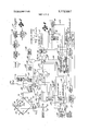
FIG. 2 is a combined schematic, logic and block diagram of the transmitter;
FIG. 3 is a combined logic and block diagram of the line monitor and hold out timer incorporated in the transmitter; and
FIG. 4 is a combined schematic and logic diagram of the switch matrix and digit code and digit sequence counters incorporated into the transmitter.
DESCRIPTION OF THE PREFERRED EMBODIMENT Turning now to the drawings, and particularly FIG. 1 thereof, the presently preferred embodiment of the event signal transmitter of the invention is intended to transmit alarm and clear signals to a central office via a dedicated telephone line in response to alarm and clear conditions at the premises, such as a building, where the transmitter is installed. In operation, one or a plurality of conventional sensors 11 may be connected to the transmitter to sense alarm and clear con ditions. The sensors 11 are connected to a control logic section 12 which determines whether an alarm or a clear event signal is to be transmitted in reponse to sensed alarm or clear conditions.
Since a device such as a burglar alarm operates for considerable periods of time in a quiescent condition, the transmitter of the invention employs a controlled power supply 15 which is activated by the control logic section 12. All of the circuitry within the transmitter which is not needed to perform the functions of the control logic section 12 or to monitor the telephone line 10 are powered by the controlled power supply 15.
When the control logic section 12 determines that an event signal is to be transmitted, the controlled power supply 15 is activated and supplies power to an event signal generator 16 and a hold-out timer 18. As briefly described above, the hold-out timer 18 monitors the telephone line 10 and if there is line activity, the timer generates a signal which is applied to the event signal generator 16 to inhibit the transmission of the event signal until the line activity ceases. If there is no line activity, the event signal generator 16 transmits the event signal over the telephone line 10 and then generates a signal which deactivates the controlled power supply 15. Thus, following the transmission of an event signal, the transmitter goes back to its quiescent condition until another event signal is to be transmitted.
Turning now to FIG. 2, the great variety of possible conventional sensors will be herein represented by a pair of foil strips 22 and 24. In general, any sensors may be used but, for the particular preferred embodiment illustrated in the drawings, the clear condition of any sensor is generally represented by a closed electrical circuit and the alarm condition as an open electrical circuit.
In the illustrated embodiment, the foil strips 22 and 24 are placed in opposite legs of a bridge circuit 14 so that the two strips may function independently. The leg of the bridge 14 containing the foil strip 22 also has two resistors R1 and R2 in series with the strip. The legs of the bridge circuit 14 containing foil strip 24 also includes a series resistor R3. The two remaining legs of the bridge contain resistors R4 and R5, respectively. In accordance with conventional bridge circuit techniques, a dc voltage V is applied to a first bridge junction point 26 and the second opposite junction point 28 is connected to ground 30. The values of resistors R1 through R5 and the foil strips 22, 24 are such that the voltage between the two remaining opposite junction points 32 and 34, respectively, is substantially zero for the clear condition. The voltage between the junction points 32, 34 is sensed by the base emitter circuit of a transistor Q1. The collector of transistor Q] is connected to. V through the series voltage divider including the resistors R6 and R7 and the junction point of these resistors is connected to the base of another transistor Q2. The emitter of transmitter O2 is connected to V and its collector is connected through a resistor R10 to ground 30.
It can be seen that, in a quiescent condition, the voltage applied to the base-emitter circuit of transistor Q1 is substantially zero resulting in very little collector current. Thus, the voltage at the junction of the resistors R6 and R7 is substantially V As the emitter of transistor O2 is connected to V and its base is substantially at a voltage level equal to V very little current flows in its base-emitter circuit also resulting in very collector current which leaves the collector of transistor Q2 substantially at ground potential.
Should either of the foil strips 22, 24 be open circuited, indicating an alarm condition, the bridge becomes unbalanced and transistor Q1 is turned on resulting in a voltage drop at the junction of resistors R6 and R7. The simultaneous voltage drop at the base of transistor Q2 also turns on that transistor driving its collector voltage toward V Thus, it can be seen that an alarm condition is represented by a voltage rise at the collector of transistor Q2.
The voltage rise at the collector of transistor 02 may be alternatively generated by means of a tamper switch SW1 which connects the base of transistor O2 to ground through a resistor R1 1. The tamper switch SW1 is situated within the housing of the transmitter so that any attempt to open the housing results in closure of the switch.
The remaining portions of the transmitter circuitry are made up of conventional logic devices which areillustrated in the drawing in their functional form. Thus, it will be understood that, for clarity, power lines have not been shown. Furthermore, it should be understood that many alternative logical configurations are possible.
The main sensor input to the control logic section 12 shown in FIG. 1 is a NOT OR gate 36- with the clear condition of the sensors being defined as a high first input 38. As described above, in the clear condition, the collector of transistor O2 is substantially at ground potential so an inverter 40 is used to generate the high input. The clear condition also requires a high second input 42 to the NOT OR gate 36 which is supplied by connecting the second input through a resistor R12 to V The two high inputs 38, 42 to NOT OR gate 36 produce a low output which is applied to the input of an inverter 44 resulting in a high output from the inverter. The high output of the inverter 44 is connected through a feedback resistor R13 to the input 38 to NOT OR gate 36. It will be appreciated that the feedback resistor R13 results in the logical form of a threshold device in that the signal fed back through resistor R13 reinforces the signal at the input 38 to NOT OR gate 36. To further increase the threshold type of operation of the input portions of the transmitter, the output of NOT OR gate 36 is connected through a resistor R14 to the junction point 34 of the bridge. Thus, it can be seen that as the output of NOT OR gate 36 goes high in response to an alarm condition, the high voltage is coupled through resistor R14 to the base of O1 to reinforce its base emitter current.
It can be seen that for the clear condition, the output of inverter 44 is high while in the alarm condition, the output of NOT OR gate 36 is high. Therefore, a high at the output of NOT OR gate 36 will be designated as alarm condition signal and a high output at inverter 44 will be designated as a clear condition signal.
One of the specifications for a transmitter of this type is that the same signal cannot be transmitted twice in a row. Therefore, in order to determine whether an alarm condition signal or a clear condition signal should be transmitted, it is necessary to know which signal was transmitted last. This knowledge is stored'in a late sent R-S flip-flop F-F in which a high Q output indicates that an alarm signal was last sent and a high 6 output indicates that a clear signal was last sent. The alarm and clear signals are logically combined in a pair of control AND gates 46 and 48 to determine if a signal is to be transmitted. Thus, the output of NOT OR gate 36 is connected to a first input 50 of the alarm AND gate 46 and the 6 output of last sent flip flip F-F is connected to a second input 52 to the gate. It can be seen that when there is an alarm signal and a clear was last sent, both the inputs 50 and 52 to alarm AND gate 46 will be high producing a high output indicating that an alarm signal is to be transmitted. Similarly, the output of inverter 44 is connected to a first input 54 to clear AND gate 48 and assuming that mode switch SW2, to be explained later, is in the A or B mode position, the Q output of last sent flip-flop F-F, is connected to a second input 56 to the gate. Thus, when a clear signal is present and an alarm signal was last sent, the two inputs 54 and 56 to clear AND gate 48 are both high and, assuming that a third input 58 to the gate is also high, the output of the gate will then be high indicating that a clear signal is to be sent.
Both of the outputs from the alarm and clear AND gates 46, 48, respectively, are connected to the inputs to an OR gate 60 so that if either an alarm or clear signal is to be transmitted, the output of OR gate 60 will be high. The output of OR gate 60 is connected to one input 62 of an AND gate 64 and assuming that a second input 66 to the gate is also high, the output of AND gate 64 is also high and is applied to the set input 68 of a power R-S flip-flop F-F The set input 68 causes the Q output of the power flip-flop F-F to go high which turns on the controlled power supply 15.
When the controlled power supply 15 is turned on, all of the remaining circuitry is powered through line 72 and set to initial conditions by means of a pulse C generated on a line 74 through a capacitor C, connected to power line 72. In particular, a clock 76 is turned on and supplies clock pulses to a conventional MOD-3 counter 78 which has been turned on and set to an initial sate by the pulse C,,. The MOD-3 counter 78 and conventional associated circuitry supplies alternating outputs on lines 80 and 82 which are applied to first inputs to a pair of AND gates 84 and 86. The AND gates 84 and 86 are enabled at their second inputs by enabling line 88. By convention, a long space is generated before numbers are transmitted on the line. Following the long space, enabling line 88 is made high in a manner to be described below and the alternating outputs 80 and 82 of the MOD-3 counter 78 activate a pair of relays 90 which open and short the telephone line as described above.
To generate the space, the clock pulses on line 77 are applied to a first input 92 to an AND gate 94 enabled by the high Q output of a space enable R-S flip-flop F-F The clock pulses are fed through AND gate 94 to a space counter 98 initially set to zero by a pulse C As will be described more fully below, the space counter 98 can count either a long space or a short space, the long space being enabled by a first digit signal on a line 100 from a digit sequence counter 102 which is set to the first digit position by pulse C Therefore, clock pulses are fed to the space counter 98 until the long space count is completed, at which time a reset signal is generated by the counter on line 104 and applied to the reset input to the space enable flip-flop F-F The resetting of flip-flop F-F disables AND gate 94 and causes the 6 output of the flip-flop to go high generating a count enable signal which enables AND gates 84 and 86 via line 88 to permit the alternating outputs 80 and 88 from the MOD-3 counter 78 to activate the relays 90.
The count enable signal also enables an AND gate 106 permitting clock pulses to be fed to a digit code counter and switch matrix 106. As will be more fully described below, the digit code counter is a four bit binary counter initially set to zero by pulse C A space enable signal will be generated on line 108 following a first digit count which was preset on the switch matrix. The digit code counter and switch matrix 106 is controlled by a digit sequence counter 102 so that three separate digits may be counted for each round of transmission. Therefore, as clock pulse are supplied to the digit code counter 106, the relays 90 are being alternatively activated to open and short the telephone line 10. A ground-open sequence switch SW3 is provided so that the sequence may be reversed for particular applications.
When the digit code counter 106 reaches the first preset digit, a space enable signal is generated on line 108 and applied to the set input of the space enable flip-flop F-F and the high Q output again enables AND gate 94 allowing clock pulses to enter the space counter 98. As the Q output of the space enable flip flop F-F goes high, the 6 output goes low disabling AND gates 106, 84 and 86. The Q output of the space enable flip-flop F-F is also applied over a line 110 to the digit code counter 106 to reset the counter to zero and through a line 112 to the digit sequence counter 102 to increment that counter to the second digit position. As the first digit signal is no longer present, the space counter counts only a short space before resetting the space enable flip-flop F-F as described above. The second digit signal from the digit sequence counter then enables the switch matrix so that counter 106 counts up to the second digit while the relays 90 are again activated.
The sequence is again repeated for the third digit and when the digit code counter 106 reaches the third digit count, the space enable signal generated on line 108 is applied to one input of an AND gate 112 which is enabled at its second input by the third digit signal. The output of AND gate 112 increments a round counter 114 previously set to zero by pulse C The digit sequence counter 102 is a MOD-3 counter and the counter cycles back to the first digit signal which enables the space counter 98 to count a long space between the first and second rounds. The number of rounds to be transmitted depends on whether an alarm or clear signal was last sent and on the position of a clear signal selector switch SW Following the transmission of the second round, the round counter 14 is incremented to the second round position, the second round signal being applied to one input 116 of an AND gate 118 in the example of FIG. 2. The enabling input 120 to AND gate 118 is from the alarm sent signal which is assumed to be low at this time for this example. Thus, the output of AND gate 118 remains low which permits the third round to be transmitted.
Following the transmission of the third round, the round counter 114 is incremented to the third digit position which is connected to the set input of the last sent flip-flop F-F, and the resulting high Q output is an alarm last sent signal, as discussed above. The third roun signal is also applied via a line 119 to a first input 120 to an OR gate 122, the high output of which resets the power flip-flop F -F turning off the controlled power supply 15.
Thus, an alarm signal has been transmitted to the central office and the last sent flip-flop F-F has been set to generate an alarm last sent signal enabling the clear AND gate 48 and disabling the alarm AND gate 46. Now, the only signal which can be transmitted next is a clear signal.
When the power flip-flop F-F, is reset, the Q output activates a conventional one shot time delay circuit 124 which in turn generates a high output on line 126 which is connected to one input to a NOR gate 128 causing the enabling second input of AND gate 64 to go low for the time period ofthe one shot time delay circuit. Therefore, even if the alarm condition had been corrected to a clear condition during the time the alarm was being transmitted, the power flip-flop F-F cannot be immediately turned on again to transmit the signal. Therefore, the telephone line 10 is inactive for the time delay period permitting another transmitter in the system to begin transmitting. Thus, a single transmitter cannot dominate the telephone line 10 when there is a continued progression of alarm and clear conditions.
The sequence of operation for the transmission of a clear signal is similar to that described above for the transmission of an alarm signal. The alarm last sent signal from the Q output of the last sent flip-flop F-F enables the clear AND gate 48 and the power flip-flop F-F is set as described above. One or two rounds of the code number are then transmitted depending upon the setting of the clear signal selector switch SW From the above description, it can be seen that an alarm or a clear signal will be transmitted whenever the correct logical conditions are satisfied. It will be appreciated that, if the transmitter is left in this operating mode continuously, alarm and clear signals will be transmitted continuously throughout the business day as, for example, doors are opened and closed. As this is an undesirable condition, the transmitter is provided with a control switch SW which has ON, TEST and OFF positions. In the OFF position, the control switch SW grounds the second input 42 to the NOT OR gate 36 forcing it into a low condition which generates an alarm signal at the output of NOT OR gate 36. Thus, the OFF condition for a transmitter of the type described is a forced alarm condition. Typically, when this forced alarm condition is detected at a central office at the opening time for a particular premises, the alarm signal is not interpreted as an actual alarm. Further, it will be appreciated that as a person enters a building during the opening hours, a number of alarm and clear signals may be transmitted as the person triggers the various sensors in the process. Thus, when a final alarm is received, it is interpreted as a transmitter in the OFF position.
When the building is to be closed for the day, the control switch is first turned to a test position which grounds the cathode of a light emitting diode 130 which serves as a display device. The anode gate of the diode 130 is connected to the output of a driver amplifier 132 whose input is the output of inverter 44, If all of the sensors are operating properly, a clear condition should exist and the light emitting diode 130 should be lighted.
It should be noted that when the control switch SW is turned to the test position, the NOT OR gate 36 is no longer forced into the alarm condition. If the diode 130 indicates that all the sensors are operating correctively, the control switch SW is then turned to the ON position. If the operation of the transmitter is not modified, a clear signal would be transmitted when the transmitter is turned on. It should als be noted that someone leaving the building through a door would cause the transmission of an alarm signal when the door was opened followed by a clear signal as the door was closed. While the transmission of these signals is acceptable for some systems, other systems require that only a single clear signal be transmitted as the building is closed for the day. For some systems, the closing clear signal is the only one permitted and an alarm signal cannot be cleared thereafter. Therefore, in the presently preferred embodiment of the transmitter, three selectable modes are provided for these most common types of operation. Modes A, B or C may be selected by means of a mode switch SW In mode A, the operation of the transmitter is as described as above and every alarm and clear signal is transmitted. In mode B, a closing sequence of events is provided in which the initial clear signal generated when the control switch SW is turned to the ON position is inhibited as well as the alarm signal when a door is opened. Only the clear signal generated when the door is closed is transmitted. Following the closing sequence, any subsequently generated alarm or clear signals will be transmitted.
In mode C, the closing sequence is also provided. However, following the closing sequence, the transmitter is conditioned to transmit only a single alarm condition. Subsequently generated clear signals are not transmitted.
The closing sequence is provided by means of a closing sequence R-S flip-flop F-F, with its high Q output serving to enable the third input 58 of the clear AND gate 48 in the B and C modes through the first section 133 of mode switch SW In the A mode, the enabling input 58 is connected through a first section 133 of the mode switch SW to the TEST position of control switch SW The set input of the closing sequence flipflop F-F is connected to V through resistor R14 and so is normally high generating a high Q output which enables a clear AND gate 48. The reset input to the closing sequence flip-flop F-F. is connected to the output of inverter 44 and therefore receives the clear signals. When the control switch SW is turned to the TEST position, the set input to the closing sequence flip-flop F-F is grounded allowing the clear signal to reset the flip-flop. The Q output of flip-flop F-F, is then low inhibiting the clear AND gate 48. When the control switch SW is then turned to the ON position, both of the set and reset inputs to the closing sequence flip-flop F-F are high resulting in no change in the outputs of the flip-flop. The clear signal which would normally be transmitted at this point is thereby inhibited. When the door is then opened, the generated alarm signal cannot be transmitted because an alarm was last sent. The output of inverter 44 is low permitting V to set the closing sequence flip-flop F-F, to enable the clear AND gate 48. Then, when the door is closed, the clear signal is again generated and all the inputs 54, 56 and 58 to clear AND gate 48 are high to start transmission of the clear signal.
To prevent transmission of any clear signals except the one of the end of the closing sequence in mode C, an auxiliary external output R-S flip-flop F-F is used. In Mode C, the Q output of flip-flop F-F is connected through the second switch section of mode switch SW to the second input 56 of the clear AND gate 48. When the control switch SW is moved from the OFF position to the TEST position, the set input to the external output flip-flop F-F is connected through resistor R12 to V setting the flip-flop. The reset input to flip-flop F-F is connected to the clear last sent signal at the Q output of the last sent flip-flop F-F which is low until the clear signal is transmitted. Following the closing sequence,
the single clear signal is transmitted resetting the last sent flip-flop F-F and resetting the external output flipflop I -F via line 135. The Q output of flip-flop F-F is then low inhibiting any further transmission of clear signals.
The 6 output of external output flip-flop F-F is connected to one input gate of an external output AND gate 134 with the other input to AND gate 134 being connected to the alarm last sent signal. Therefore, following the transmission of an alarm signal, an external output signal will appear on line 136 which may be used to turn on a bell or other type of alarm in the building.
It will be appreciated that the closing sequence in modes B and C inhibits transmission of only a single clear signal followed by an alarm signal. If the person closing the building has to go through only one sensor, such as that on the door, the closing sequence is sufficient. However, if the person closing the building has to go through a number of different sensors, each of which produces an alarm and clear condition, the closing sequence is satisfied afer the first sensor is encountered and all subsequent alarm and clear signals will be transmitted. To prevent this, an optional auxiliary exit delay timer 138 may be provided. When the control .switch SW is turned to the ON position, the exit delay timer is activated through line 140 and generates an inhibiting output which is connected to a second input 142 to NOR gate 128. The AND gate 64 is thus inhibited and the power flip-flop F-F cannot be set. In the presently preferred embodiment of the invention, the exit delay timer provides the inhibiting signal for a nominal 60 seconds which is sufficient time to permit someone to leave the building. With the exit delay timer 138 in operation, any number of alarm and clear signals can be generated, none of which will be transmitted. Presumably, after the building is closed, a clear condition exists and when the exit delay timer 138 goes off and AND gate 64 is again enabled, the clear signal will be transmitted. The configuration of the exit delay timer is conventional and any of a wide variety of timing circuits may be utilized.
Turning now to FIG. 3, the hold out timer 18 which monitors the telephone line 10 is shown in detail. The telephone line 10 is connected to an active filter 144 of conventional design which filters out substantially all signals on the telephone line except the relatively low frequency open and shorting signals of another similar transmitter on the line. When such activity is sensed, the active filter triggers a Schmidt trigger 146 which generates a line-active signal which is applied to an inverter 148 which then has a low output. Due to the time spaces between transmitted digits, a temporary cessation of line activity may not mean that transmission is complete. Therefore, a 6 second time delay is provided as represented by capacitor C before the line-open signal as represented by a high at the output of inverter 148 is again generated.
As was briefly stated above, hold out timers in the prior art used the cessation of line activity as the basic starting time and if all the transmitters had the same basic timing circuit, theoretically, all of the transmitters contending for the line would try to begin transmitting at the same time. In the hold out timer of the present invention, the basic starting time is keyed to the occurrence of an event at the transmitter and not to the state of the telephone line 10. Thus, an auxiliary hold out timer clock 150 is provided which, for the presently preferred embodiment, has a basic clock period of seconds. The clock 150 feeds a conventional four bit binary counter 152. The clock 150, counter 152 and associated logic circuitry are all powered by the controlled power supply 15. Assuming that there is no activity on the line, when the controlled power supply is turned on, the pulse C is applied to all flip-flops within the counter 152 to reset the counter to zero. The pulse C is also applied to the reset input of a time delay R-S flip-flop F-F thereby causing a low Q output. Pulse C is further applied to the reset input of a clock inhibit R-S flip-flop F-F tending to cause the 6 output of the flip-flop to go high as a main clock inhibit signal. However, the pulse C is also applied to one input of an AND gate 154, the gate being enabled by the line-open signal at the output of inverter 148. The then high output of AND gate 154 is applied to one input of an OR gate 156 whose output sets the clock inhibit flip-flop RE. The generation of the output of OR gate 156 is delayed for a short time period by means of a capacitor C connected from the output of AND gate 154 to ground 30. Thus, while the pulse C starts to reset the clock inhibit flip-flop F-F,, the delayed clock pulse C at the output of OR gate 156 immediately tends to set the flip-flop back again. Thus, if there is no line activity, the main clock inhibit signal is not generated and transmission of the event signal proceeds as described above.
If there should be line activity when the controlled power supply 15 is turned on, the output of inverter 148 is low and AND gate 154 is inhibited. Therefore, pulse C cannot set the clock inhibit flip-flop F-F and the main clock inhibit signal is generated to prevent the main clock 76 from starting. As the transmission of signals is dependent on the operation of the clock 76, event signals cannot be transmitted.
As noted above, the basic clock period for the hold out timer clock 150 is ten seconds and after two clock periods, or seconds, the second flip-flop in counter 152 will have a high Q output which is applied to the set input 158 of the time delay flip-flop F-F The then high Q output from flip-flop F-F is applied to one input of an AND gate 160. A second input to AND gate 160 is the output of inverter 148 which may or may not be high depending on the condition of the telephone line 10. A third input to AND gate 160 is the clock pulse from clock 150 itself. Thus, it can be seen that if the line activity ceases after the time delay of 20 seconds, the output of inverter 148 will then go high but the AND gate 160 cannot develop an output signal until the next clock pulse from clock 150. Therefore, the basic hold out time is still controlled by the occurrence of the event which started the clock 150. Therefore, after the expiration of the 20 second time delay and the occurrence of a line-open signal from inverter 148 and a clock pulse from clock 150, AND gate 160 develops a high output which is applied through OR gate 156 to the set input of the clock inhibit flip-flop F-F,. The main clock inhibit signal then goes low enabling clock 76 to start and the transmission of event signals is as described above.
If a line-active signal remains due to some extraordinary activity on the line such as jamming or interference, transmission is positively started when a count o f 16 is reached by counter 152. At that time, the high Q of the last flip-flop in the counter 152 is connected through a capacitor C to OR gate 156 to the set input of the clock inhibit flip-flop F-F-,. Thus, the transmitter will begin transmitting at the end of seconds regardless of the state of the telephone line 10.
Turning now to FIG. 4, the digit code counter and switch matrix 106, the digit sequence counter 102 and the space counter 98 and its associated logic circuits are shown in detail. The digit code counter 106 is a conventional four bit binary counter 164. The switch matrix includes three sets of switches 166, 168 and 170, respectively, corresponding to the three digit capability of the illustrated embodiment of the transmitter. Each set of switches 166, 168 and includes four switches. The pole terminal of each switch can be connected to either the Q output of a flip-flop in the counter 164 or directly to controlled power through a series resistor R15.
The pole terminals of each set of switches 166, 168 and 170 are all connected as inputs to associated AND gates 172, 174 and 176, respectively. Each of the AND gates 172, 174 and 176 have first, second and third digit enabling lines 100, 180 and 182, respectively, connected to the digit sequence counter 102. When the switches within a particular set are set to the Q outputs of the flip-flops in counter 164, it can be seen that all of the inputs to the associated AND gate will be high only when the appropriate Q outputs of the flip-flops in counter 164 are high. Thus, any four bit binary digit can be set on the switches and when the counter reaches that four bit binary number, the associated AND gate will generate a high output if properly enabled.
Signals on enabling lines 100, 180 and 182 are generated by a digit sequence counter 102 which includes a pair of J-K flip-flops F-F and F-F The flip-flops F-F and F-F are conventionally connected as a MOD-3 counter and appropriate outputs from flip-flops F-F and F-F are conventionally combined by AND gates 184, 186 and 188 to generate the first, second and third digit enabling signals on lines 100, 180 and 182, respectively. As is true with all of the logic circuitry in FIG. 4, the flip-flops F-F and F-F are under controlled power and are reset to an initial state by the pulse C which is applied to the flip-flops through an inverter 190 which normally maintains the K input to flip-flop F-F in a high condition.
Because the digit sequence counter 102 is not under main clock control, if the counter should happen to get into its fourth state because of a noise pulse, for example, there would be no way to trigger the counter out of that state. Therefore, an auxiliary NAND gate 192 is provided to detect when the counter 102 is in that fourth state and to generate a signal on line 194 to trigger the counter out of that state.
As briefly described above, the space counter 98 provides a long space between rounds and a shorter space between digits. The counter 98 includes a pair of J-K flip-flops F-F and F-F connected to produce an output signal after two clock pulses for the short space and to produce an output pulse after four clock pulses when enabled for the long space.
Thus, when transmission is to begin, a long space is transmitted prior to the transmission of digits. The pulse C conditions the digit sequence counter 102 so that the first digit enabling line 100 is high. The first digit enable signal is also applied to the J input of flipflop F-F in the space counter and to one input of a NAND gate 196. The NAND gate 196 controls an AND gate 198 which receives strobing pulses from the Q output of flip-flop F-F through a capacitor C The output of AND gate 198 is connected to the reset input of the count space flip-flop F-F Flip-flop F-F generates a space enable signal at its Q output which enables the AND gate 94 to permit clock pulses on line 92 to reach the trigger input of flip-flop F-F Flip-flop F-F is connected so that it changes its state on each clock pulse so that on the second clock pulse, a strobing pulse is sent to AND gate 198. However, that second clock pulse also changes the state of flip-flop F-F and its Q output, combined with the first digit enable signal at NAND gate 196 produces an inhibiting signal at AND gate 198 preventing the strobing pulse from reaching the round space flip-flop F-F At the fourth clock pulse, the strobing pulse is again delivered to AND gate 198 and flip-flop F-F changes state again removing the inhibiting signal from AND 198 so that the pulse is delivered to the reset input of the round space flip-flop F-F A round enable signal is then generated at the 6 output of flip-flop F-F and the low Q inhibit AND gate 92 stopping clock pulses from reaching the space counter.
The round enable signal enables the AND gate 106 which permits clock pulses on line 77 to enter the digit code counter 164 to count up to the digit set on the first set of switches 166. When all of the inputs to AND gate 172 are high, an output is generated which is connected through an OR gate 200 to the set input of the round space flip-flop F-F via line 108, as described above. The generated space enable signal then enables AND gate 94 permitting the next space to be counted by space counter 98.
It should be noted that the round enable signal is connected to the trigger inputs of the flip-flops F-F and F-F, in the digit sequence counter and when the round enable signal goes from its high to low state, the flipflops are clocked to permit the generation of the second digit enable signal on line 180. Thus, the first digit enable signal on line 100 is turned off which in turn conditions the flip-flop F-F and NAND gate 196 so that AND gate 198 cannot be inhibited. Thus, it can be seen that the strobing pulse will be delivered through gate 198 at the end of the second clock pulse for the short space.
The operation proceeds as described above through the three digits encoded on the sets of switches 166, 168 and 170. When the third digit is transmitted, the digit sequence counter is shifted back to the first digit enable state to transmit another complete round if needed. It should be noted that the third digit enable signal on line 182 is connected to the trigger input of the round counter 114 and when the signal goes from the high to its low state, the round counter is clocked. If the required number of rounds has been transmitted, the controlled power supply is turned off as described above.
Thus, the presently preferred embodiment of the event signal transmitter of the invention is easily programable to simulate a number of different types of operation. Therefore, a single transmitter may be used in a variety of different alarm systems for which specially designed transmitters formerly had to be supplied.
While a particular presently preferred embodiment of the transmitter of the invention has been described in detail above, it will be appreciated that a number of variations in circuit and component design are possible and therefore, the scope of the invention is not to be limited except by the following claims. I claim:
1. An event signal transmitter for common connection to a transmission line with a plurality of other transmitters, said transmitter comprising:
event sensing means for sensing a plurality of different events;
event signal generating means for generating event signals corresponding to said events;
control means connected to said sensing means and to said generating means for controlling transmission of said event signals over said transmission lines;
line monitoring means connected to said control means and to said transmission line for sensing activity on said transmission line, said monitoring means generating a line-active signal in the presence of line activity and a line-open signal a first predetermined time period after the cessation of such activity, said monitoring means further having an event signal delay means for delaying a gener ated event signal for a second predetermined time period to produce a delayed event signal, and a delay clock means for generating delay clock pulses in response to generation of said event signal, transmission of said event signal being inhibited by said line-active signal and transmission being initiated upon coincidence of said line-open signal and said event signal or said line-open signal, said delayed event signal and a delay clock pulse.
2. The event signal transmitter defined in claim 1 including:
mode selection means connected to said control means for preselecting a plurality of sequences of event signals to be generated in response to particular sequences of sensing of events by said sensing means.
3. The event signal transmitter defined in claim l including:
controlled power supply means for selectively supplying power to said event signal generating means and said event signal delay means, said controlled power supply means being under the control of said control means.
4. The event signal transmitter defined in claim 1, wherein said event sensing means includes:
a bridge circuit with individual sensors in legs of said bridge circuit; and
feedback means connected to said bridge circuit for providing a threshold type event signal when an event is sensed;
5. The event signal transmitter as defined in claim 1 wherein:
said event signal delay means further delays said event signal for a third predetermined time period longer than said second predetermined time period, an override signal being generated at the end of said third predetermined time period to initiate transmission of said event signal despite the presence of said line-active signal.
6. The event signal transmitter defined in claim 5 including:
controlled power supply means for selectively supplying power to said event signal generating means and said event signal delay means, said controlled power supply means being under the control of said control means.
7. The event signal transmitter defined in claim 6 wherein said event sensing means includes:
a bridge circuit with individual sensors in legs of said bridge circuit; and
feedback means connected to said bridge circuit for providing a threshold type event signal when an event is sensed.
8. The event signal transmitter as defined in claim 1 including:
mode selection means for preselecting a plurality of modes of operation for said transmitter, said modes being defined as the selective inhibition of the transmission of particular sequences of event signals.
9. The event signal transmitter defined in claim 8, including:
controlled power supply means for selectively supplying power to said event signal generating means and said event signal delay means, said controlled power supply means being under the control of said control means.
10. The event signal transmitter defined in claim 9 wherein:
said event signal delay means further delays said event signal for a third predetermined time period longer than said second predetermined time period, an override signal being generated at the end of said third predetermined time period to initiate transmission of said event signal despite the presence of said line-active signal.
11. The event signal transmitter defined in claim 10, wherein said event sensing means includes:
a bridge circuit with individual sensors in legs of said bridge circuit; and
feedback means connected to said bridge circuit for providing a threshold type event signal when an event is sensed.
12. An event signal transmitter for use in an alarm system in which a plurality of transmitters are commonly connected on a single transmission line to a central office, said transmitter comprising:
event sensing means for sensing an alarm or a clear condition;
event signal generating means for generating an alarm or a clear signal, and transmitting said alarm or clear signal to said central office, said alarm signal being defined as the transmission of a code number for said transmitter a first predetermined number of rounds and said clear signal being defined as the transmission of said code number a second predetermined number of rounds;
control means connected to said event sensing means and said event signal generating means for controlling transmission of said event signals over said transmission line;
line monitoring means connected to said control means and to said transmission line for sensing activity on said line, said monitoring means generating a line-active signal in the presence of line activity and a line-open signal a first predetermined time period after the cessation of such activity;
event signal delay means for delaying transmission of a generated event signal for a second predetermined time period to produce a delayed event signal, and a delay clock means for generating delay clocl clock pulses in response to said delayed event signal, transmission of said event signal being inhibited by said line-active signal and transmission being initiated upon coincidence of said line-open signal and said event signal or said line-open signal, said delayed event signal and a delay clock pulse. 13. The event signal generating means defined in claim 12, including:
controlled power supply means for selectively supplying power to said event signal generating means and to said event signal delay means, said controlled power supply means being controlled by said control means. 14. The event signal transmitter defined in claim 12, wherein said control means includes:
control switch means for selectively providing OFF,
TEST and ON operation positions for said transmitter, said OFF position forcing said transmitter into an alarm condition, the alarm or clear condition of said transmitter being displayed in said TEST position and the transmitter being made operational in said ON position. 15. The event signal transmitter defined in claim 14 wherein said control means includes:
mode switch means for selectively providing first,
second and third operating modes for said transmitter when said control switch means is in said ON position, said first mode permitting the transmission of all alarm or clear signals, said second mode inhibiting the transmission of an initial clear signal and alarm signal when said control switch means is put into said ON position and thereafter permitting the transmission of all alarm or clear signals and said third mode inhibiting the transmission of an initial clear signal and alarm signal when said control switch means is put into said ON position and thereafter permitting the transmission of only one alarm signal. 16. The event signal transmitter defined in claim 15 wherein:
said event signal delay means further delays said event signal for a third predetermined time period longer than said second predetermined time period, an override signal being generated at the end of said third predetermined time period to initiate transmission of said event signal despite the presence of said line-active signal. 17. The event signal transmitter defined in claim 16 including:
controlled power supply means for selectively supplying power to said event signal generating means and to said event signal delay means, said controlled power supply means being controlled by said control means. 18. The event signal transmitter defined in claim 14 wherein said event signal generating means includes:
clear signal selector switch means for preselecting said second predetermined number of rounds. 19. The event signal transmitter defined in claim 18 wherein:
said second predetermined number of rounds may be selected as one or two rounds, said first predetermined number being three rounds. 20. The event signal transmitter defined in claim 18 wherein said event signal generating means includes:
means for opening the circuit of said transmission line through said transmitter;
means for shorting said transmission line to ground;
and sequence selection switch means for preselecting sequence of opening and shorting said transmission line. 21. The event signal transmitter defined in claim 20 including:
controlled power supply means for selectively supplying power to said event signal generating means and to said event signal delay means, said controlled power supply means being controlled by said control means. 22. The event signal transmitter defined in claim 20 wherein:
said event signal delay means further delays said event signal for a third predetermined time period longer than said second predetermined time period, an override signal being generated at the end of said third predetermined time period to initiate transmission of said event signal despite the presence of said line-active signal. 23. The event signal transmitter defined in claim 22 wherein said control switch means further includes:
mode switch means for selectively providing first,
second and third operating modes for said transmitter when said control switch means is in said ON position, said first mode permitting the transmission of all alarm or clear signals, said second inhibiting the transmission of an initial clear signal and alarm signal when said control switch means is put into said ON position and thereafter permitting the transmission of all alarm or clear signals and said third mode inhibiting the transmission of an initial clear signal and alarm signal when said control switch means is put into said ON position and thereafter permitting the transmission of only one alarm signal.
24. The event signal transmitter defined in claim 23 including:
controlled power supply meand for selectively supply power to said event signal generating means and to said event signal delay means, said controlled power supply means being controlled by said control means.
25. The event signal transmitter defined in claim 24 wherein said event sensing means includes:
a bridge circuit with individual sensors in legs of said bridge circuit; and
feedback means connected to said bridge circuit for providing a threshold type event signal when an event is sensed.
feedback means connected to said bridge circuit for providing a threshold type event signal when an event is sensed.
UNITED STATES PATENT AND TRADEMARK OFFICE CERTIFICATE OF CORRECTION PATENT NO. 3,772,667
DATED November 15, 1971 lNV ENTOR(S) MELVIN S. FALK, JR.
It is certified that error appears in the above-identified patent and that said Letters Patent are hereby corrected as shown below:
In FIG. 3 of the drawings, delete the line that connects the output of the inverter 148 directly to the uppermost input of OR gate 156.
Signed and Scaled this A Fifth Day Of December 1973 [SEAL] Anal:
RUTH MASON DONALD W. BANNER Amm'ng Ofl'wer Commissioner ofPammud Trademarks 'qgggg UNITED STATES PATENT "OFFICE CERTIFICATE CORRECTION Patent N 2.772667 Date Nnvpm'h 'r' 12 mm Inventofls) MELVIN s. FALCK, JR.
It is certified that error appears in the aboveeidentified patent and that said Letters Patent are hereby corrected as shown below:
I. On the title page, delete the title Y 1 "EVENT SIGNAL TRANSMITTER HAVING EVENT SIGNAL DISPLAYING MEANS" and insert therefor -SIGNAL TRANSMITTER--.
Column'3, line 15, delete "in" and inserttherefor -to-. I 7
Column 6, line 28, delete "sate" and insert therefor -state-.
Column 7, line 47, after "alarm" insert --last-; line 56, delete "roun" and insert therefor --round--.
Column 8, line 51, delete "44," and insert therefor -44.--; line 58, delete "correctively" and insert therefor --correctly--; line 62, delete "als" and insert therefor --also--.
Column 11, line 66, after "5" insert -output--.
Column 13, line 56, delete "the" (first occurrence) and insert therefor --its.
"UNIT D STATES PATENT OFFICE Page 2 CERTIFICATE OF CORREQTION PatentNo- 2.772.667 Dated ma 13 1923 Invento -(s) S. JR.
It is certified that error appears in the above-identified patent and that 'said Letters Patent are hereby corrected as shown below:
Signed and sealed this 7th day of May 197M.
(SEAL) Attest:
EDWARD M .PLETGEE R J R I C MARSHALL DAEIN Attesting Officer Commissioner of Patents )RM PO-105O (10-69) uscoMM-Dc 60376-P69 i U. 5. GOVERNMENT PRINTING OFFICE I9, O-Jl-SJL
Claims (25)
1. An event signal transmitter for common connection to a transmission line with a plurality of other transmitters, said transmitter comprising: event sensing means for sensing a plurality of different events; event signal generating means for generating event signals corresponding to said events; control means connected to said sensing means and to said generating means for controlling transmission of said event signals over said transmission lines; line monitoring means connected to said control means and to said transmission line for sensing activity on said transmission line, said monitoring means generating a lineactive signal in the presence of line activity and a line-open signal a first predetermined time period after the cessation of such activity, said monitoring means further having an event signal delay means for delaying a generated event signal for a second predetermined time period to produce a delayed event signal, and a delay clock means for generating delay clock pulses in response to generation of said event signal, transmission of said event signal being inhibited by said lineactive signal and transmission being initiated upon coincidence of said line-open signal and said event signal or said lineopen signal, said delayed event signal and a delay clock pulse.
2. The event signal transmitter defined in claim 1 including: mode selection means connected to said control means for preselecting a plurality of sequences of event signals to be generated in response to particular sequences of sensing of events by said sensing means.
3. The event signal transmitter defined in claim 1 including: controlled power supply means for selectively supplying power to said event signal generating means and said event signal delay means, said controlled power supply means being under the control of said control means.
4. The event signal transmitter defined in claim 1, wherein said event sensing means includes: a bridge circuit with individual sensors in legs of said bridge circuit; and feedback means connected to said bridge circuit for providing a threshold type event signal when an event is sensed.
5. The event signal transmitter as defined in claim 1 wherein: said event signal delay means further delays said event signal for a third predetermined time period longer than said second predetermined time period, an override signal being generated at the end of said third predetermined time period to initiate transmission of said event signal despite the presence of said line-active signal.
6. The event signal transmitter defined in claim 5 including: controlled power supply means for selectively supplying power to said event signal generating means and said event signal delay means, said controlled power supply means being under the control of said control means.
7. The event signal transmitter defined in claim 6 wherein said event sensing means includes: a bridge circuit with individual sensors in legs of said bridge circuit; and feedback means connected to said bridge circuit for providing a threshold type event signal when an event is sensed.
8. The event signal transmitter as defined in claim 1 including: mode selection means for preselecting a plurality of modes of operation for said transmitter, said modes being defIned as the selective inhibition of the transmission of particular sequences of event signals.
9. The event signal transmitter defined in claim 8, including: controlled power supply means for selectively supplying power to said event signal generating means and said event signal delay means, said controlled power supply means being under the control of said control means.
10. The event signal transmitter defined in claim 9 wherein: said event signal delay means further delays said event signal for a third predetermined time period longer than said second predetermined time period, an override signal being generated at the end of said third predetermined time period to initiate transmission of said event signal despite the presence of said line-active signal.
11. The event signal transmitter defined in claim 10, wherein said event sensing means includes: a bridge circuit with individual sensors in legs of said bridge circuit; and feedback means connected to said bridge circuit for providing a threshold type event signal when an event is sensed.
12. An event signal transmitter for use in an alarm system in which a plurality of transmitters are commonly connected on a single transmission line to a central office, said transmitter comprising: event sensing means for sensing an alarm or a clear condition; event signal generating means for generating an alarm or a clear signal, and transmitting said alarm or clear signal to said central office, said alarm signal being defined as the transmission of a code number for said transmitter a first predetermined number of rounds and said clear signal being defined as the transmission of said code number a second predetermined number of rounds; control means connected to said event sensing means and said event signal generating means for controlling transmission of said event signals over said transmission line; line monitoring means connected to said control means and to said transmission line for sensing activity on said line, said monitoring means generating a line-active signal in the presence of line activity and a line-open signal a first predetermined time period after the cessation of such activity; event signal delay means for delaying transmission of a generated event signal for a second predetermined time period to produce a delayed event signal, and a delay clock means for generating delay clocl clock pulses in response to said delayed event signal, transmission of said event signal being inhibited by said line-active signal and transmission being initiated upon coincidence of said line-open signal and said event signal or said line-open signal, said delayed event signal and a delay clock pulse.
13. The event signal generating means defined in claim 12, including: controlled power supply means for selectively supplying power to said event signal generating means and to said event signal delay means, said controlled power supply means being controlled by said control means.
14. The event signal transmitter defined in claim 12, wherein said control means includes: control switch means for selectively providing OFF, TEST and ON operation positions for said transmitter, said OFF position forcing said transmitter into an alarm condition, the alarm or clear condition of said transmitter being displayed in said TEST position and the transmitter being made operational in said ON position.
15. The event signal transmitter defined in claim 14 wherein said control means includes: mode switch means for selectively providing first, second and third operating modes for said transmitter when said control switch means is in said ON position, said first mode permitting the transmission of all alarm or clear signals, said second mode inhibiting the transmission of an initial clear signal and alarm signal when said control switch means is put into said ON position and thereafter permitting the transmission of all alarm or clear signals and said third moDe inhibiting the transmission of an initial clear signal and alarm signal when said control switch means is put into said ON position and thereafter permitting the transmission of only one alarm signal.
16. The event signal transmitter defined in claim 15 wherein: said event signal delay means further delays said event signal for a third predetermined time period longer than said second predetermined time period, an override signal being generated at the end of said third predetermined time period to initiate transmission of said event signal despite the presence of said line-active signal.
17. The event signal transmitter defined in claim 16 including: controlled power supply means for selectively supplying power to said event signal generating means and to said event signal delay means, said controlled power supply means being controlled by said control means.
18. The event signal transmitter defined in claim 14 wherein said event signal generating means includes: clear signal selector switch means for preselecting said second predetermined number of rounds.
19. The event signal transmitter defined in claim 18 wherein: said second predetermined number of rounds may be selected as one or two rounds, said first predetermined number being three rounds.
20. The event signal transmitter defined in claim 18 wherein said event signal generating means includes: means for opening the circuit of said transmission line through said transmitter; means for shorting said transmission line to ground; and sequence selection switch means for preselecting sequence of opening and shorting said transmission line.
21. The event signal transmitter defined in claim 20 including: controlled power supply means for selectively supplying power to said event signal generating means and to said event signal delay means, said controlled power supply means being controlled by said control means.
22. The event signal transmitter defined in claim 20 wherein: said event signal delay means further delays said event signal for a third predetermined time period longer than said second predetermined time period, an override signal being generated at the end of said third predetermined time period to initiate transmission of said event signal despite the presence of said line-active signal.
23. The event signal transmitter defined in claim 22 wherein said control switch means further includes: mode switch means for selectively providing first, second and third operating modes for said transmitter when said control switch means is in said ON position, said first mode permitting the transmission of all alarm or clear signals, said second inhibiting the transmission of an initial clear signal and alarm signal when said control switch means is put into said ON position and thereafter permitting the transmission of all alarm or clear signals and said third mode inhibiting the transmission of an initial clear signal and alarm signal when said control switch means is put into said ON position and thereafter permitting the transmission of only one alarm signal.
24. The event signal transmitter defined in claim 23 including: controlled power supply meand for selectively supply power to said event signal generating means and to said event signal delay means, said controlled power supply means being controlled by said control means.
25. The event signal transmitter defined in claim 24 wherein said event sensing means includes: a bridge circuit with individual sensors in legs of said bridge circuit; and feedback means connected to said bridge circuit for providing a threshold type event signal when an event is sensed. feedback means connected to said bridge circuit for providing a threshold type event signal when an event is sensed.
Applications Claiming Priority (1)
| Application Number | Priority Date | Filing Date | Title |
|---|---|---|---|
| US19854371A | 1971-11-15 | 1971-11-15 |
Publications (1)
| Publication Number | Publication Date |
|---|---|
| US3772667A true US3772667A (en) | 1973-11-13 |
Family
ID=22733822
Family Applications (1)
| Application Number | Title | Priority Date | Filing Date |
|---|---|---|---|
| US00198543A Expired - Lifetime US3772667A (en) | 1971-11-15 | 1971-11-15 | Event signal transmitter having event signal displaying means |
Country Status (1)
| Country | Link |
|---|---|
| US (1) | US3772667A (en) |
Cited By (7)
| Publication number | Priority date | Publication date | Assignee | Title |
|---|---|---|---|---|
| US4013959A (en) * | 1976-03-05 | 1977-03-22 | General Electric Company | Transmitter control apparatus |
| US4023139A (en) * | 1974-10-24 | 1977-05-10 | Gene Samburg | Security control and alarm system |
| US4470039A (en) * | 1982-09-23 | 1984-09-04 | American Standard Inc. | Premise alarm shunt arrangement |
| US4535598A (en) * | 1984-05-14 | 1985-08-20 | Carrier Corporation | Method and control system for verifying sensor operation in a refrigeration system |
| US4755792A (en) * | 1985-06-13 | 1988-07-05 | Black & Decker Inc. | Security control system |
| US20080061959A1 (en) * | 2002-06-11 | 2008-03-13 | Intelligent Technologies International, Inc. | Structural monitoring |
| US8994546B2 (en) | 2002-06-11 | 2015-03-31 | Intelligent Technologies International, Inc. | Remote monitoring of material storage containers |
Citations (6)
| Publication number | Priority date | Publication date | Assignee | Title |
|---|---|---|---|---|
| US3147465A (en) * | 1960-12-27 | 1964-09-01 | Mine Safety Appliances Co | Methane alarm and control system |
| US3184728A (en) * | 1962-03-26 | 1965-05-18 | Smith Kline French Lab | Null balancing indicator |
| US3320602A (en) * | 1964-07-17 | 1967-05-16 | Mc Graw Edison Co | Fire detector systems having false alarm prevention |
| US3484771A (en) * | 1966-12-22 | 1969-12-16 | Morse Products Mfg | Alarm system |
| US3550111A (en) * | 1966-08-16 | 1970-12-22 | Harold D Ervin | Security alarm system |
| US3582925A (en) * | 1967-08-08 | 1971-06-01 | Beta Corp | Indicator modules for annunciator systems |
-
1971
- 1971-11-15 US US00198543A patent/US3772667A/en not_active Expired - Lifetime
Patent Citations (6)
| Publication number | Priority date | Publication date | Assignee | Title |
|---|---|---|---|---|
| US3147465A (en) * | 1960-12-27 | 1964-09-01 | Mine Safety Appliances Co | Methane alarm and control system |
| US3184728A (en) * | 1962-03-26 | 1965-05-18 | Smith Kline French Lab | Null balancing indicator |
| US3320602A (en) * | 1964-07-17 | 1967-05-16 | Mc Graw Edison Co | Fire detector systems having false alarm prevention |
| US3550111A (en) * | 1966-08-16 | 1970-12-22 | Harold D Ervin | Security alarm system |
| US3484771A (en) * | 1966-12-22 | 1969-12-16 | Morse Products Mfg | Alarm system |
| US3582925A (en) * | 1967-08-08 | 1971-06-01 | Beta Corp | Indicator modules for annunciator systems |
Cited By (7)
| Publication number | Priority date | Publication date | Assignee | Title |
|---|---|---|---|---|
| US4023139A (en) * | 1974-10-24 | 1977-05-10 | Gene Samburg | Security control and alarm system |
| US4013959A (en) * | 1976-03-05 | 1977-03-22 | General Electric Company | Transmitter control apparatus |
| US4470039A (en) * | 1982-09-23 | 1984-09-04 | American Standard Inc. | Premise alarm shunt arrangement |
| US4535598A (en) * | 1984-05-14 | 1985-08-20 | Carrier Corporation | Method and control system for verifying sensor operation in a refrigeration system |
| US4755792A (en) * | 1985-06-13 | 1988-07-05 | Black & Decker Inc. | Security control system |
| US20080061959A1 (en) * | 2002-06-11 | 2008-03-13 | Intelligent Technologies International, Inc. | Structural monitoring |
| US8994546B2 (en) | 2002-06-11 | 2015-03-31 | Intelligent Technologies International, Inc. | Remote monitoring of material storage containers |
Similar Documents
| Publication | Publication Date | Title |
|---|---|---|
| US3953769A (en) | Electronic security control system | |
| US4755792A (en) | Security control system | |
| CA1277394C (en) | Accessory-expandable, radio-controlled, door operator with multiple security levels | |
| US4348582A (en) | Communication via an electricity supply main | |
| US4731810A (en) | Neighborhood home security system | |
| US4532507A (en) | Security system with multiple levels of access | |
| US3909826A (en) | Plural transceiver alarm system using coded alarm message and every station display of alarm origin | |
| US4396910A (en) | Coded security switch | |
| US3735396A (en) | Alarm signalling network | |
| US3689888A (en) | Pulse position modulated alarm system | |
| EP0174707A1 (en) | Burglar alarm built in car stereo | |
| US4631527A (en) | Transmitter-receiver coded security alarm system | |
| WO1987005731A1 (en) | Single-wire loop alarm system | |
| US3979740A (en) | Monitoring system | |
| US3772667A (en) | Event signal transmitter having event signal displaying means | |
| US3611361A (en) | Alarm-monitoring system | |
| EP0206483A2 (en) | Security control system | |
| EP0405247B1 (en) | Line interruption supervisory device for fire alarm systems | |
| US4016360A (en) | System for remotely checking equipment | |
| US4093870A (en) | Apparatus for testing reflexes and/or for functioning as a combination lock | |
| US4001772A (en) | Coded signaling and control system | |
| CA1181506A (en) | Security system with multiple levels of access | |
| US3792470A (en) | Coded tone multiplexed alarm transmission system | |
| US3962696A (en) | Protective systems | |
| US4145617A (en) | Control circuit for providing time selected application of A.C. power |