US3740144A - Method and apparatus for optically detecting the presence of an element in a substance - Google Patents
Method and apparatus for optically detecting the presence of an element in a substance Download PDFInfo
- Publication number
- US3740144A US3740144A US00200775A US3740144DA US3740144A US 3740144 A US3740144 A US 3740144A US 00200775 A US00200775 A US 00200775A US 3740144D A US3740144D A US 3740144DA US 3740144 A US3740144 A US 3740144A
- Authority
- US
- United States
- Prior art keywords
- signal
- wave lengths
- band
- egg
- oscillating
- Prior art date
- Legal status (The legal status is an assumption and is not a legal conclusion. Google has not performed a legal analysis and makes no representation as to the accuracy of the status listed.)
- Expired - Lifetime
Links
- 239000000126 substance Substances 0.000 title claims description 23
- 238000000034 method Methods 0.000 title claims description 12
- 235000013601 eggs Nutrition 0.000 claims abstract description 93
- 239000008280 blood Substances 0.000 claims abstract description 57
- 210000004369 blood Anatomy 0.000 claims abstract description 57
- 230000010355 oscillation Effects 0.000 claims abstract description 10
- 238000010521 absorption reaction Methods 0.000 abstract description 15
- 230000000717 retained effect Effects 0.000 abstract description 2
- 230000005540 biological transmission Effects 0.000 description 10
- 230000003287 optical effect Effects 0.000 description 5
- 230000035945 sensitivity Effects 0.000 description 5
- 238000012360 testing method Methods 0.000 description 5
- 238000001514 detection method Methods 0.000 description 3
- 238000005259 measurement Methods 0.000 description 3
- 230000002238 attenuated effect Effects 0.000 description 2
- 102000001554 Hemoglobins Human genes 0.000 description 1
- 108010054147 Hemoglobins Proteins 0.000 description 1
- 210000000078 claw Anatomy 0.000 description 1
- 239000011248 coating agent Substances 0.000 description 1
- 238000000576 coating method Methods 0.000 description 1
- 239000003086 colorant Substances 0.000 description 1
- 238000010276 construction Methods 0.000 description 1
- 230000007423 decrease Effects 0.000 description 1
- 230000001419 dependent effect Effects 0.000 description 1
- 238000010586 diagram Methods 0.000 description 1
- 230000000694 effects Effects 0.000 description 1
- 210000002969 egg yolk Anatomy 0.000 description 1
- 230000005669 field effect Effects 0.000 description 1
- 239000004615 ingredient Substances 0.000 description 1
- 230000003595 spectral effect Effects 0.000 description 1
- 238000001228 spectrum Methods 0.000 description 1
- 230000002195 synergetic effect Effects 0.000 description 1
Images


Classifications
-
- G—PHYSICS
- G01—MEASURING; TESTING
- G01J—MEASUREMENT OF INTENSITY, VELOCITY, SPECTRAL CONTENT, POLARISATION, PHASE OR PULSE CHARACTERISTICS OF INFRARED, VISIBLE OR ULTRAVIOLET LIGHT; COLORIMETRY; RADIATION PYROMETRY
- G01J3/00—Spectrometry; Spectrophotometry; Monochromators; Measuring colours
- G01J3/28—Investigating the spectrum
- G01J3/42—Absorption spectrometry; Double beam spectrometry; Flicker spectrometry; Reflection spectrometry
- G01J3/433—Modulation spectrometry; Derivative spectrometry
-
- A—HUMAN NECESSITIES
- A01—AGRICULTURE; FORESTRY; ANIMAL HUSBANDRY; HUNTING; TRAPPING; FISHING
- A01K—ANIMAL HUSBANDRY; CARE OF BIRDS, FISHES, INSECTS; FISHING; REARING OR BREEDING ANIMALS, NOT OTHERWISE PROVIDED FOR; NEW BREEDS OF ANIMALS
- A01K43/00—Testing, sorting or cleaning eggs ; Conveying devices ; Pick-up devices
Definitions
- ABSTRACT A system for detecting blood in eggs in which a beam of substantially monochromatic light or at least light within a very narrow wavelength band in the region of 578 nanometers (nm) is passed through an egg to be tested. The band is continually shifted in wavelength a number of times per second between substantially the shortest and the mid-length wavelengths of the broader blood absorption band, i.e. 578 to 573 nm.
- this is effected by a Fabry-Perot type interference filter placed in a light beam and oscillated about an axis by an electromagnetic device'
- a photoelectric device senses the light transmitted by the egg and the output signal derived therefrom is compared with an oscillating signal transmitted in time with the oscillation of the filter. If one phase relation exists between such signals, the egg is rejected as having blood present therein and if an opposite phase relation exists, the egg is retained as clear.
- CM MPATOR PHAJE f'iaa F METHOD AND APPARATUS FOR OPTICALLY DETECTING THE PRESENCE OF AN ELEMENT IN A SUBSTANCE BACKGROUND OF THE INVENTION 1.
- This invention relates to a method and apparatus for optically detecting certain properties of a substance by detecting differences in color emitted by the substance without modifying or affecting the substance itself.
- Automatic apparatus for detecting blood in eggs by impinging on an egg a beam of colored light comprising a very narrow band of wavelengths within that portion of the spectrum which is absorbed by blood and employing a photosensitive device to measure the light transmitted by the egg. Since the light falling on the photo-sensitive device is attenuated appreciably when an egg having blood therein is tested, due to absorption by the blood, such measurement can be used to segregate blood eggs from clear eggs.
- the density of eggs varies considerably due to several factors, such as the thickness of the shell, color of the shell, color of the yolk, and age of the egg which affects the density of the albumen in the egg. Because of such variations in density in different eggs it is not feasible to use a fixed reference of light values with which the amount of light transmitted by various eggs being tested can be compared to indicate the presence of blood. For example, the transmission of light in the 578 nm region through non-blood eggs of various shell thicknesses, colors, etc., has been found to vary from approximately 4 to 13 percent, whereas the attenuation due to absorption of such light by blood present within the egg may be less than 1 percent.
- the most successful prior art devices generally provide a reference obtained by passing light of a wavelength which is not affected by the presence of blood, through the egg being tested. Such reference standard is then compared with light of a wavelength within the blood absorption band which has been transmitted through the same egg. If the ratio between such two different wavelengths is greater than a predetermined amount, the egg is rejected as having blood present therein.
- a predetermined amount the percentage of available light is transmitted by an egg and, of that, less than 1 percent may be absorbed by blood so that the detecting device must be extremely sensitive and discriminating.
- this has resulted in relatively complex and expensive equipment which is not entirely reliable.
- blood detecting equipment commonly in use at present generally requires multiple optical systems which may include relatively expensive filters, lens systems, photosensitive devices and associated electronic equipment to establish, on one hand, a reference level for the average density of an egg being tested and, on the other hand, a level of light in the blood absorption band which is passed through the egg.
- Other equipment requires different filters to be sequentially positioned in a light beam passed through the egg to establish the reference and sample light values.
- the present invention provides a simpler, less expensive and yet more reliable detecting apparatus.
- a single optical system including a single narrow bandpass light filter is employed, in which the filter is continually oscillated in the light beam in a manner to shift the essential or peak wavelength a number of times a second between the shortest and mid-length wavelengths of the blood absorption band, such wavelengths normally being 578 nm and 573 nrn, respectively.
- the constantly changing filtered beam is passed through the egg and the light transmitted thereby is collected onto a photosensitive device.
- the output signal of the photosensitive device is compared with an oscillating signal derived from the filter oscillating means and, if blood is present, the signals will be found to be in a particular phase relationship. If no blood is present, an opposite phase relationship will exist.
- Phase comparing means is employed to reject blood eggs. Since the result is dependent upon the phase relationship of the signals and not upon the degree of sensitivity of any part of the system or upon any measurements of the amount of light transmitted by the egg being tested, the system becomes entirely reliable regardless of such variables as the quality of the light source or the quality of the components. Also, since the system employs collimated light to pass through the single filter onto the egg, all of the light passing through the egg may be collected for detection, thus increasing the sensitivity of the system far above the threshold of detection.
- a collimated light beam passes through a narrow bandpass filter of the dielectric or Fabry-Perot interference type and the resulting essentially monochromatic light in the 578 nm region is then passed through the egg being tested and the transmitted light is focused onto a photoelectric device.
- the filter is continuously oscillated about an axis to vary the essential wavelength of the band between approximately the shortest and midlength wavelength in the blood absorption band. Means are provided to adjust the filter so that the highest wavelength limit may be precisely set. Therefore, relatively inexpensive filters having wide spectral tolerances may be employed since they can be readily adjusted to the desired wavelength.
- the filter is oscillated on opposite sides of its position of maximum wavelength transmission during each oscillation cycle so that the frequency of oscillation thereof is only onehalf the frequency of optical scanning, thereby reducing wear and vibration of the mechanical components and improving the speed of test by having a higher frequency electrical signal.
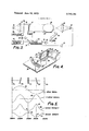
- FIG. 1 is a schematic view showing waves depicting the percentage of light transmission at different wavelengths by eggs having different overall densities.
- FIG. 2 is an enlarged view showing a curve representing a typical dip in the light transmission at different wavelengths due to absorption by blood within an egg.
- FIG. 3 is a schematic view of a system embodying a preferred form of the invention for rejecting blood eggs.
- FIG. 4 is a perspective view of the filter support and adjustment.
- FIG. 5 is a view illustrating the phase relationship of the filter drive signal and the output of the photosensitive device for blood eggs and clear eggs.
- FIG. 6 is a schematic view of a modified form of the invention employing a wedge type rotary dielectric or interference filter.
- FIG. 7 is a developed view illustrating the relative change in wavelength transmission and potentiometer voltage output around the rotary filter of FIG. 6.
- FIG. 8 is a schematic view of a modified form of the invention employing a tunable laser.
- FIG. 9 is a circuit diagram of the phase comparator.
- FIG. 10 shows the signal waveforms developed at different points in the phase comparator circuit.
- line 11 illustrates the percentage of light transmission for different wavelengths of light passed through a typical day-old egg having a relatively thin white shell and containing blood.
- Line 12 illustrates the percentage transmission for light passed through a typical older egg having a colored shell and also containing blood. It will be noted that the dip at 13, caused by the absorption of blood in the region of 578 nm, effects a much smaller change in light transmission than the variables resulting from shell thickness, shell color, age, etc.
- the wavelength of the light transmitted through the egg is oscillated between limits preferably representing essentially the shortest and the mid-length of wavelengths within the blood absorption band, i.e., between 578 nm and 573 nm.
- limits preferably representing essentially the shortest and the mid-length of wavelengths within the blood absorption band, i.e., between 578 nm and 573 nm.
- the apparatus disclosed therein comprises a light source 14 and a collimator lens 15 for projecting a continuous collimated beam of light 16.
- a dielectric or Fabry-Perot type interference filter 17 which passes a very narrow light band in the 578 nm region is located in the beam.
- Eggs, i.e., 18, to be tested are carried past the beam 16 on a suitable conveyor 19.
- a lens 20 focuses the transmitted light onto a suitable photodiode 21, the output of which is amplified by amplifier 22 and fed over line to the lower input of a phase comparator 23.
- the filter 17 is mounted in a frame 24, FIG. 4, supported by trunnion bearings 25 in a support 26 for movement about a horizontal axis 27 passing through the plane of the filter.
- the support 26 is pivotally supported by a bearing 28 on a base 30 for movement about a vertical axis 31 intersecting the axis 27.
- the support 26 may be locked in different adjusted positions about axis 31 by a lock screw 33 which extends through an arcuate slot 34 in the support and is threaded into the base 30.
- An arm 35 is attached to the frame 24 and is pivotally connected to the armature 36 of a solenoid 37 suitably mounted on the support 26.
- the solenoid 37 is driven by an oscillator 38, preferably at the rate of approximately 47 cycles per second so that the filter is oscillated a number of times while each egg intercepts the beam 16. Thus, a number of separate tests are made of each egg to further insure reliable results.
- each cycle involves an excursion of the filter 17 on opposite sides of a plane normal to the axis of beam 16 and that the transmitted wavelength decreases as the filter moves on either side of such normal plane so that the resulting optical frequency of the wavelength shift is twice that of the oscillation of the filter.
- the output signal of the oscillator 38 is fed through a frequency doubler circuit 41 of conventional construction and over line 71.
- the resulting signal is fed to the upper input of the comparator circuit 23.
- the output of the latter is fed through an amplifier 43 and over line 73 to the solenoid 44 of an egg rejector device 45.
- the latter is effective, upon energization of the solenoid 44, to eject an egg being tested off the conveyer l9 and into a suitable receptacle (not shown) for blood eggs.
- the filter 17 is first adjusted about its vertical axis 31 with the filter in a vertical plane as depicted at 17a, 17c, or 17e (FIG. 5) until it passes a wavelength of essentially 578 nm which represents the point of maximum absorption of oxidized blood hemoglobin.
- the amplitude of the drive signal developed by the oscillator 38 is preferably adjusted, as by a potentiometer 47, so that the filter, when at the limits of its excursion in either direction, as depicted at 17b and 17d, will pass a wavelength of essentially 573 nm which represents the point b at the lower end of the blood absorption curve of FIG. 2.
- the photodiode 21 will develop a signal represented by curve 48 of FIG. 5. That is, when the beam 16 constitutes light at essentially 578 nm, the signal developed by the photodiode 21 will be at a minimum, as indicated at 51, due to the maximum absorption by the blood at such wavelength. However, the developed signal will be at a maximum, as indicated at 52, when the beam 16 constitutes light at essentially 573 nm.
- the phase comparator circuit 23 will apply a drive signal through amplifier 43 to energize the solenoid 44 to eject the blood egg.
- the photodiode 21 when a clear egg intercepts the beam 16, the photodiode 21 will develop a signal represented by line 53 which is in direct phase relation to the shift in wavelength of the beam 16. That is, when the beam 16 constitutes light at 578 nm, the signal will be at a maximum, as indicated at 54. However, when the beam 16 shifts to the shorter wavelength of 573 nm, the signal will be at a minimum, as indicated at 55. In this case, the comparator circuit will not apply a drive signal to the ejecting means.
- the rejection signal is developed entirely independently of the overall density of the egg and of any measurement of the amount of light attenuated by blood present in the egg but, instead, is determined solely by whether the response of the photodiode 21 follows the gradient represented by the curve a-b of FIG. 2 or the gradient represented by the curve b-c.
- a light polarizing filter 56 may be inserted in the beam 16.
- FIG. 6 illustrates a modified form of the invention in which elements similar to those of FIG. 1 are identified by similar reference numerals.
- the oscillating filter 17 of FIG. 3 is replaced by a rotating filter disc 57 of the dielectric or Fabry-Perot interference type which is rotated at a constant speed by a motor 58.
- the disc has an interference coating which gradually changes through 360 in order to shift the wavelength of the narrow band beam passing therethrough from essentially 578 nm to 573 nm.
- the developed curve 60 of FIG. 7 illustrates the bandpass characteristic of the disc through 360 of rotation.
- the motor 58 is mounted on a bracket 61 which, in turn, is mounted on a base 62 for adjustment about a vertical axis 63.
- a lock screw 64 is effective to lock the motor in any adjusted position.
- the motor is adjusted about axis 63 until such wavelength is precisely 578 nm.
- a rotary potentiometer 64 is driven by the motor and its output is connected to the upper input of the phase comparator circuit 23.
- the output of the potentiometer is indicated by the curve 65 in relation to the wavelength curve 60.
- the system of FIG. 6 operates the same as that of FIG. 3.
- the motor 58- is preferably operated at a speed such that the light beam will be shifted between 578 nm and 573 nm a number of times while each egg intercepts such beam. Thus, a number of independent tests are made of each egg to further insure reliability.
- FIG. 8 illustrates a further modified form of the invention in which elements similar to those found in FIG. 1 are identified by the same reference numerals.
- the filter 17 of FIG. 1 is replaced by a tunable laser 66 which is capable of varying the wavelength of the emitted beam 67 from 578 nm to 573 nm under control of oscillator circuit 38.
- the circuit 38 is directly connected to the upper input of the phase comparator circuit 23.
- Tunable lasers of this type are commercially available, for example, from Synergistic s, Inc. of Princeton, NJ.
- a suitable diffuser 68 is located in the beam 67 to disperse the beam over the projected area of the egg 18.
- FIG. 8 operates the same as that of FIG. 3.
- the oscillator circuit 38 is preferably operated at such a rate that the light beam 67 will be shifted between 578 nm and 573 nm a number of times while each egg intercepts the dispersed component of such beam.
- FIGS. 9 and 10 illustrate a preferred form of the phase comparator circuit and the resulting signal waveform.
- the signal received over line 71 from the frequency doubler circuit 41 is squared by clipping diodes 73, 74 and shunted by diode 75 and amplifier 76 (see C). Such signal is inverted by inverter circuit 77 (see E) and the direct and inverted components of the signal are fed over lines 78 and 79 and through diodes 80 and 81, to control field effect transistors 82 and 83, respectively.
- the signal received over line 70 from the photodiode 21 is amplified by amplifier circuit 84 (see B). Part of such signal is controlled by transistor 83 and another part is inverted by amplifier circuit 85 and controlled by transistor 82.
- the resulting components of both the direct and inverted parts of the signal 8 are combined at point 86 (see D) and are fed through an integrator 87 to a voltage comparator circuit 88 resulting in a waveform (see E) which, if blood is present, becomes increasingly more positive potential until, at the end of the test period, the control threshold for the egg ejecting device is exceeded. If, on the other hand, blood is absent, the resulting waveform becomes of increasingly more negative potential and is therefore ineffective to control the ejecting device.
- the integrating comparator 90 across integrator 87 is shorted by a switch 91 between eggs and when no eggs are being tested.
- limiting wave lengths comprise substantially a mid-length wave length and a wave length within and adjacent one end of said particular band.
- the method of detecting eggs having blood therein comprising the steps of passing a light beam of a narrow band of wave lengths through an egg being tested,
- Apparatus for detecting the presence of an element in a substance wherein said element is effective to absorb radiant energy within a particular band of wave lengths comprising means for directing a beam of radiant energy of a narrow band of wave lengths within said particular band through said substance and for oscillating the wave lengths of said narrow band substantially between a mid-length wave length and a wave length within and adjacent one end of said particular band,
- photosensitive means for receiving that portion of said beam passing through said substance and for creating a first signal which varies with the intensity of the radiant energy contained in said portion of said beam
- limiting wavelengths comprise substantially the shortest and the mid-length wavelengths in said particular band.
- Apparatus for detecting eggs having blood therein comprising means for passing a light beam of a narrow band of wave lengths within a particular band of wave lengths absorbed by blood through an egg being tested and for oscillating the wave lengths of said narrow beam between substantially the shortest and the midlength wave length within said particular band,
- photosensitive means for receiving that portion of said beam passing through said egg and for creating a first signal which varies with the intensity of the light contained in said portion of said beam
- said first mentioned means comprises means including a light source
- Apparatus according to claim 8 comprising means supporting said filter for adjustment about a second axis normal to said first axis whereby to change the wave lengths passed by said filter at one end of the oscillation thereof.
- said means for creating said second signal comprises means controlled by said oscillating means for oscillating said second signal at twice the frequency of oscillation of said filter.
- said first mentioned means comprises means including a light source; and a rotatable dielectric band pass filter in said beam,
- said filter oscillating said wave lengths of said narrow band during rotation of said filter.
- Apparatus according to claim 7 comprising means for conveying said eggs past said beam and wherein said first mentioned means oscillates the lengths of said narrow band a plurality of times while each of said eggs is in said beam.
Abstract
A system for detecting blood in eggs in which a beam of substantially monochromatic light or at least light within a very narrow wavelength band in the region of 578 nanometers (nm) is passed through an egg to be tested. The band is continually shifted in wavelength a number of times per second between substantially the shortest and the mid-length wavelengths of the broader blood absorption band, i.e. 578 to 573 nm. In a preferred embodiment, this is effected by a Fabry-Perot type interference filter placed in a light beam and oscillated about an axis by an electromagnetic device. A photoelectric device senses the light transmitted by the egg and the output signal derived therefrom is compared with an oscillating signal transmitted in time with the oscillation of the filter. If one phase relation exists between such signals, the egg is rejected as having blood present therein and if an opposite phase relation exists, the egg is retained as clear.
Description
aac allm mi j if, KR EJ740910;
unuteu claws rawlll 1 Walker METHOD AND APPARATUS FOR OPTICALLY DETECTING THE PRESENCE OF AN ELEMENT IN A SUBSTANCE [76] Inventor: Winston G. Walker, 909 E. Balsam Ave., Apt. D, Anaheim, Calif. 92805 [22] Filed: Nov. 22, 1971 [21] App]. No.: 200,775
Primary ExaminerRonald L. Wibert Assistant Examiner-Paul K. Godwin Attorney-Fred N. Schwend .38 I OSCILLATOR I 47 5? 4! f 23 FREQUENCY PHASE DOUBLE? ECOMPAPATOP 1 June 19, 1973 [57] ABSTRACT A system for detecting blood in eggs in which a beam of substantially monochromatic light or at least light within a very narrow wavelength band in the region of 578 nanometers (nm) is passed through an egg to be tested. The band is continually shifted in wavelength a number of times per second between substantially the shortest and the mid-length wavelengths of the broader blood absorption band, i.e. 578 to 573 nm. ln a preferred embodiment, this is effected by a Fabry-Perot type interference filter placed in a light beam and oscillated about an axis by an electromagnetic device' A photoelectric device senses the light transmitted by the egg and the output signal derived therefrom is compared with an oscillating signal transmitted in time with the oscillation of the filter. If one phase relation exists between such signals, the egg is rejected as having blood present therein and if an opposite phase relation exists, the egg is retained as clear.
13 Claims, 10 Drawing Figures DRIVE .SIGNAL BIOOD PRESENT B1. 000 ABSE NT Patented June 19, 1973 4 Sheets-Sheet PHA SE d-v COMPAPA 70? F PEOUENC Y DOUBLE? ZDP/Vf SIGNAL BlwD PPE'SFNT NBA M 173 .55 awoo ABSENT I 53 578 573W Patented June 19, 1973 4 Sheets-Sheet 3 FIG. 6
CM MPATOR PHAJE f'iaa F METHOD AND APPARATUS FOR OPTICALLY DETECTING THE PRESENCE OF AN ELEMENT IN A SUBSTANCE BACKGROUND OF THE INVENTION 1. Field of the Invention This invention relates to a method and apparatus for optically detecting certain properties of a substance by detecting differences in color emitted by the substance without modifying or affecting the substance itself.
2. Description of the Prior Art Detecting devices of the above type have been used heretofore in which the optical characteristics of a substance have been analyzed photoelectrically in testing for a particular property or ingredient. One particularly difficult application of this type of analysis is the detection of small amounts of blood which are occasionally found in eggs.
Automatic apparatus have been developed for detecting blood in eggs by impinging on an egg a beam of colored light comprising a very narrow band of wavelengths within that portion of the spectrum which is absorbed by blood and employing a photosensitive device to measure the light transmitted by the egg. Since the light falling on the photo-sensitive device is attenuated appreciably when an egg having blood therein is tested, due to absorption by the blood, such measurement can be used to segregate blood eggs from clear eggs.
However, the density of eggs varies considerably due to several factors, such as the thickness of the shell, color of the shell, color of the yolk, and age of the egg which affects the density of the albumen in the egg. Because of such variations in density in different eggs it is not feasible to use a fixed reference of light values with which the amount of light transmitted by various eggs being tested can be compared to indicate the presence of blood. For example, the transmission of light in the 578 nm region through non-blood eggs of various shell thicknesses, colors, etc., has been found to vary from approximately 4 to 13 percent, whereas the attenuation due to absorption of such light by blood present within the egg may be less than 1 percent.
Accordingly, the most successful prior art devices generally provide a reference obtained by passing light of a wavelength which is not affected by the presence of blood, through the egg being tested. Such reference standard is then compared with light of a wavelength within the blood absorption band which has been transmitted through the same egg. If the ratio between such two different wavelengths is greater than a predetermined amount, the egg is rejected as having blood present therein. As noted above, only a small amount of available light is transmitted by an egg and, of that, less than 1 percent may be absorbed by blood so that the detecting device must be extremely sensitive and discriminating. Heretofore, this has resulted in relatively complex and expensive equipment which is not entirely reliable. For example, analysis of eggs tested by currently available automatic blood detecting equipment shows that at least 5 percent of all eggs having blood present therein are allowed to pass undetected. Also, blood detecting equipment commonly in use at present generally requires multiple optical systems which may include relatively expensive filters, lens systems, photosensitive devices and associated electronic equipment to establish, on one hand, a reference level for the average density of an egg being tested and, on the other hand, a level of light in the blood absorption band which is passed through the egg. Other equipment requires different filters to be sequentially positioned in a light beam passed through the egg to establish the reference and sample light values.
Another problem in presently available blood detecting equipment is that very narrow and, therefore, expensive band pass light filters are required in order to obtain sufficient sensitivity to detect small amounts of blood in eggs being tested. Also, such filters require collimated light. However, the diffused light transmitted by an egg can be collimated only by utilizing a small fraction of such light, thereby reducing the total amount of light available to the detecting device. Other systems using a prism or grating type monochrometer require a very narrow beam restricting slit for proper resolution of the blood absorption band and therefore the total available light is relatively small, thus reducing the sensitivity of the system.
SUMMARY OF THE INVENTION The present invention provides a simpler, less expensive and yet more reliable detecting apparatus. According to a preferred form of this invention, only a single optical system including a single narrow bandpass light filter is employed, in which the filter is continually oscillated in the light beam in a manner to shift the essential or peak wavelength a number of times a second between the shortest and mid-length wavelengths of the blood absorption band, such wavelengths normally being 578 nm and 573 nrn, respectively. The constantly changing filtered beam is passed through the egg and the light transmitted thereby is collected onto a photosensitive device. The output signal of the photosensitive device is compared with an oscillating signal derived from the filter oscillating means and, if blood is present, the signals will be found to be in a particular phase relationship. If no blood is present, an opposite phase relationship will exist. Phase comparing means is employed to reject blood eggs. Since the result is dependent upon the phase relationship of the signals and not upon the degree of sensitivity of any part of the system or upon any measurements of the amount of light transmitted by the egg being tested, the system becomes entirely reliable regardless of such variables as the quality of the light source or the quality of the components. Also, since the system employs collimated light to pass through the single filter onto the egg, all of the light passing through the egg may be collected for detection, thus increasing the sensitivity of the system far above the threshold of detection.
In the preferred embodiment of the invention, a collimated light beam passes through a narrow bandpass filter of the dielectric or Fabry-Perot interference type and the resulting essentially monochromatic light in the 578 nm region is then passed through the egg being tested and the transmitted light is focused onto a photoelectric device. The filter is continuously oscillated about an axis to vary the essential wavelength of the band between approximately the shortest and midlength wavelength in the blood absorption band. Means are provided to adjust the filter so that the highest wavelength limit may be precisely set. Therefore, relatively inexpensive filters having wide spectral tolerances may be employed since they can be readily adjusted to the desired wavelength.
Also, according to the invention, the filter is oscillated on opposite sides of its position of maximum wavelength transmission during each oscillation cycle so that the frequency of oscillation thereof is only onehalf the frequency of optical scanning, thereby reducing wear and vibration of the mechanical components and improving the speed of test by having a higher frequency electrical signal.
BRIEF DESCRIPTION OF THE DRAWINGS FIG. 1 is a schematic view showing waves depicting the percentage of light transmission at different wavelengths by eggs having different overall densities.
FIG. 2 is an enlarged view showing a curve representing a typical dip in the light transmission at different wavelengths due to absorption by blood within an egg.
FIG. 3 is a schematic view of a system embodying a preferred form of the invention for rejecting blood eggs.
FIG. 4 is a perspective view of the filter support and adjustment.
FIG. 5 is a view illustrating the phase relationship of the filter drive signal and the output of the photosensitive device for blood eggs and clear eggs.
FIG. 6 is a schematic view of a modified form of the invention employing a wedge type rotary dielectric or interference filter.
FIG. 7 is a developed view illustrating the relative change in wavelength transmission and potentiometer voltage output around the rotary filter of FIG. 6.
FIG. 8 is a schematic view of a modified form of the invention employing a tunable laser.
FIG. 9 is a circuit diagram of the phase comparator.
FIG. 10 shows the signal waveforms developed at different points in the phase comparator circuit.
DETAILED DESCRIPTION OF THE EMBODIMENTS Referring to FIG. 1, line 11 illustrates the percentage of light transmission for different wavelengths of light passed through a typical day-old egg having a relatively thin white shell and containing blood. Line 12 illustrates the percentage transmission for light passed through a typical older egg having a colored shell and also containing blood. It will be noted that the dip at 13, caused by the absorption of blood in the region of 578 nm, effects a much smaller change in light transmission than the variables resulting from shell thickness, shell color, age, etc.
According to the present invention, and as shown in the magnified curve of FIG. 2, the wavelength of the light transmitted through the egg is oscillated between limits preferably representing essentially the shortest and the mid-length of wavelengths within the blood absorption band, i.e., between 578 nm and 573 nm. Thus, if blood is present, the character of the light transmitted by the egg will essentially correspond to that portion of the transmission curve from a to b whereas if no blood is present, the character of the light transmitted will essentially correspond to that portion of the alternate transmission curve'from b to 0.
Referring to FIG. 3, the apparatus disclosed therein comprises a light source 14 and a collimator lens 15 for projecting a continuous collimated beam of light 16. A dielectric or Fabry-Perot type interference filter 17 which passes a very narrow light band in the 578 nm region is located in the beam.
Eggs, i.e., 18, to be tested are carried past the beam 16 on a suitable conveyor 19. As each egg passes through the beam 16, a lens 20 focuses the transmitted light onto a suitable photodiode 21, the output of which is amplified by amplifier 22 and fed over line to the lower input of a phase comparator 23. The filter 17 is mounted in a frame 24, FIG. 4, supported by trunnion bearings 25 in a support 26 for movement about a horizontal axis 27 passing through the plane of the filter. The support 26 is pivotally supported by a bearing 28 on a base 30 for movement about a vertical axis 31 intersecting the axis 27. The support 26 may be locked in different adjusted positions about axis 31 by a lock screw 33 which extends through an arcuate slot 34 in the support and is threaded into the base 30.
An arm 35 is attached to the frame 24 and is pivotally connected to the armature 36 of a solenoid 37 suitably mounted on the support 26. By adjusting the point 39 of pivotal connection along the arm 35 the amplitude of oscillation of the filter may be changed. The solenoid 37 is driven by an oscillator 38, preferably at the rate of approximately 47 cycles per second so that the filter is oscillated a number of times while each egg intercepts the beam 16. Thus, a number of separate tests are made of each egg to further insure reliable results. It should be noted that each cycle involves an excursion of the filter 17 on opposite sides of a plane normal to the axis of beam 16 and that the transmitted wavelength decreases as the filter moves on either side of such normal plane so that the resulting optical frequency of the wavelength shift is twice that of the oscillation of the filter.
The output signal of the oscillator 38, as indicated by line 40 in FIG. 5, is fed through a frequency doubler circuit 41 of conventional construction and over line 71. The resulting signal, as indicated by curve 42, is fed to the upper input of the comparator circuit 23. The output of the latter is fed through an amplifier 43 and over line 73 to the solenoid 44 of an egg rejector device 45. The latter is effective, upon energization of the solenoid 44, to eject an egg being tested off the conveyer l9 and into a suitable receptacle (not shown) for blood eggs.
In operating the apparatus, the filter 17 is first adjusted about its vertical axis 31 with the filter in a vertical plane as depicted at 17a, 17c, or 17e (FIG. 5) until it passes a wavelength of essentially 578 nm which represents the point of maximum absorption of oxidized blood hemoglobin. The amplitude of the drive signal developed by the oscillator 38 is preferably adjusted, as by a potentiometer 47, so that the filter, when at the limits of its excursion in either direction, as depicted at 17b and 17d, will pass a wavelength of essentially 573 nm which represents the point b at the lower end of the blood absorption curve of FIG. 2.
Now, when a blood egg intercepts the beam 16, the photodiode 21 will develop a signal represented by curve 48 of FIG. 5. That is, when the beam 16 constitutes light at essentially 578 nm, the signal developed by the photodiode 21 will be at a minimum, as indicated at 51, due to the maximum absorption by the blood at such wavelength. However, the developed signal will be at a maximum, as indicated at 52, when the beam 16 constitutes light at essentially 573 nm. Thus, when the signals from the photodiode 21 and from the frequency doubler circuit are in their relative positions shown by curves 42 and 48, the phase comparator circuit 23 will apply a drive signal through amplifier 43 to energize the solenoid 44 to eject the blood egg.
On the other hand, when a clear egg intercepts the beam 16, the photodiode 21 will develop a signal represented by line 53 which is in direct phase relation to the shift in wavelength of the beam 16. That is, when the beam 16 constitutes light at 578 nm, the signal will be at a maximum, as indicated at 54. However, when the beam 16 shifts to the shorter wavelength of 573 nm, the signal will be at a minimum, as indicated at 55. In this case, the comparator circuit will not apply a drive signal to the ejecting means.
It will be noted from the foregoing that the rejection signal is developed entirely independently of the overall density of the egg and of any measurement of the amount of light attenuated by blood present in the egg but, instead, is determined solely by whether the response of the photodiode 21 follows the gradient represented by the curve a-b of FIG. 2 or the gradient represented by the curve b-c.
In order to improve the sensitivity of the system, a light polarizing filter 56 may be inserted in the beam 16.
FIG. 6 illustrates a modified form of the invention in which elements similar to those of FIG. 1 are identified by similar reference numerals. In this case, the oscillating filter 17 of FIG. 3 is replaced by a rotating filter disc 57 of the dielectric or Fabry-Perot interference type which is rotated at a constant speed by a motor 58. The disc has an interference coating which gradually changes through 360 in order to shift the wavelength of the narrow band beam passing therethrough from essentially 578 nm to 573 nm. The developed curve 60 of FIG. 7 illustrates the bandpass characteristic of the disc through 360 of rotation.
The motor 58 is mounted on a bracket 61 which, in turn, is mounted on a base 62 for adjustment about a vertical axis 63. A lock screw 64 is effective to lock the motor in any adjusted position. Preferably, when the disc 57 is in a rotated position in which it passes the longest wavelength, the motor is adjusted about axis 63 until such wavelength is precisely 578 nm.
A rotary potentiometer 64 is driven by the motor and its output is connected to the upper input of the phase comparator circuit 23. The output of the potentiometer is indicated by the curve 65 in relation to the wavelength curve 60. In other respects, the system of FIG. 6 operates the same as that of FIG. 3.
The motor 58-is preferably operated at a speed such that the light beam will be shifted between 578 nm and 573 nm a number of times while each egg intercepts such beam. Thus, a number of independent tests are made of each egg to further insure reliability.
FIG. 8 illustrates a further modified form of the invention in which elements similar to those found in FIG. 1 are identified by the same reference numerals. Here, the filter 17 of FIG. 1 is replaced by a tunable laser 66 which is capable of varying the wavelength of the emitted beam 67 from 578 nm to 573 nm under control of oscillator circuit 38. In this case, the circuit 38 is directly connected to the upper input of the phase comparator circuit 23. Tunable lasers of this type are commercially available, for example, from Synergistic s, Inc. of Princeton, NJ.
A suitable diffuser 68 is located in the beam 67 to disperse the beam over the projected area of the egg 18.
In other respects, the system of FIG. 8 operates the same as that of FIG. 3.
The oscillator circuit 38 is preferably operated at such a rate that the light beam 67 will be shifted between 578 nm and 573 nm a number of times while each egg intercepts the dispersed component of such beam.
FIGS. 9 and 10 illustrate a preferred form of the phase comparator circuit and the resulting signal waveform.
The signal received over line 71 from the frequency doubler circuit 41 is squared by clipping diodes 73, 74 and shunted by diode 75 and amplifier 76 (see C). Such signal is inverted by inverter circuit 77 (see E) and the direct and inverted components of the signal are fed over lines 78 and 79 and through diodes 80 and 81, to control field effect transistors 82 and 83, respectively.
The signal received over line 70 from the photodiode 21 is amplified by amplifier circuit 84 (see B). Part of such signal is controlled by transistor 83 and another part is inverted by amplifier circuit 85 and controlled by transistor 82. The resulting components of both the direct and inverted parts of the signal 8 are combined at point 86 (see D) and are fed through an integrator 87 to a voltage comparator circuit 88 resulting in a waveform (see E) which, if blood is present, becomes increasingly more positive potential until, at the end of the test period, the control threshold for the egg ejecting device is exceeded. If, on the other hand, blood is absent, the resulting waveform becomes of increasingly more negative potential and is therefore ineffective to control the ejecting device.
The integrating comparator 90 across integrator 87 is shorted by a switch 91 between eggs and when no eggs are being tested.
What is claimed is:
l. The method of detecting the presence of an element in a substance wherein said element is effective to absorb radiant energy within a particular band of wave lengths, comprising the steps of passing a radiant energy beam of a narrow band of wave lengths within said particular band through said substance,
oscillating the wave lengths of said narrow band between predetermined limiting wave lengths within said particular band,
converting that portion if said beam which passes through said substance into a first signal which varies in accordance with the intensity of said portion of said beam, creating a second signal which varies in accordance with the wave lengths of said narrow band, and
creating a third signal indicative of the presence of said element in said substance when a predetermined phase relationship occurs between said first signal and said second signal. 2. The method accordingto claim 1 wherein said limiting wave lengths comprise substantially a mid-length wave length and a wave length within and adjacent one end of said particular band.
3. The method of detecting eggs having blood therein comprising the steps of passing a light beam of a narrow band of wave lengths through an egg being tested,
oscillating the lengths of said wave lengths in said narrow band at least substantially between 578nm and 573nm,
converting that portion of said beam which passes through said egg into a first signal which varies in accordance with the density of said portion of said beam,
creating a second signal which varies in accordance with the wave lengths of said narrow band, and creating a third signal only when said second signal varies substantially in phase with said first signal to indicate the presence of blood in said egg.
4. The method according to claim 3 which comprises conveying said eggs past said beam, and
oscillating said wave lengths of said narrow band a plurality of times while each of said eggs is in said beam.
5. Apparatus for detecting the presence of an element in a substance wherein said element is effective to absorb radiant energy within a particular band of wave lengths, comprising means for directing a beam of radiant energy of a narrow band of wave lengths within said particular band through said substance and for oscillating the wave lengths of said narrow band substantially between a mid-length wave length and a wave length within and adjacent one end of said particular band,
photosensitive means for receiving that portion of said beam passing through said substance and for creating a first signal which varies with the intensity of the radiant energy contained in said portion of said beam,
means controlled by said first mentioned means for creating a second signal which varies with the wave lengths of said narrow band,
a signal device for indicating the presence of said element in the said substance, and
means for comparing the phase relationship between said first and said second signals and for actuating said signal device when a predetermined phase relationship exists between said first and second signals.
6. Apparatus according to claim 5 wherein said limiting wavelengths comprise substantially the shortest and the mid-length wavelengths in said particular band.
7. Apparatus for detecting eggs having blood therein comprising means for passing a light beam of a narrow band of wave lengths within a particular band of wave lengths absorbed by blood through an egg being tested and for oscillating the wave lengths of said narrow beam between substantially the shortest and the midlength wave length within said particular band,
photosensitive means for receiving that portion of said beam passing through said egg and for creating a first signal which varies with the intensity of the light contained in said portion of said beam,
means controlled by said first mentioned means for creating a second signal which varies with the wave lengths of said narrow beam,
an egg ejecting device, and
means for comparing the phase relationship between said first and second signals and for causing operation of said ejecting device when said first and second signals are substantially in phase.
8. Apparatus according to claim 7 wherein said first mentioned means comprises means including a light source,
a dielectric band pass filter in said beam, and
means for oscillating said filter about an axis extending parallel to the plane of said filter whereby to oscillate the wave lengths of said narrow band.
9. Apparatus according to claim 8 comprising means supporting said filter for adjustment about a second axis normal to said first axis whereby to change the wave lengths passed by said filter at one end of the oscillation thereof.
10. Apparatus according to claim 8 wherein said oscillating means oscillates said filter equal amounts on opposite sides of a plane normal to the length of said beam, and
said means for creating said second signal comprises means controlled by said oscillating means for oscillating said second signal at twice the frequency of oscillation of said filter.
11. Apparatus according to claim 7 wherein said first mentioned means comprises means including a light source; and a rotatable dielectric band pass filter in said beam,
said filter oscillating said wave lengths of said narrow band during rotation of said filter.
12. Apparatus according to claim 7 wherein said first mentioned means comprises a tunable laser,
oscillating means, and
means controlled by said oscillating means for tuning said laser to change the wavelength of light emitted by said laser between substantially said shortest and said mid-length wavelength.
13. Apparatus according to claim 7 comprising means for conveying said eggs past said beam and wherein said first mentioned means oscillates the lengths of said narrow band a plurality of times while each of said eggs is in said beam.
Claims (13)
1. The method of detecting the presence of an element in a substance wherein said element is effective to absorb radiant energy within a particular band of wave lengths, comprising the steps of passing a radiant energy beam of a narrow band of wave lengths within said particular band through said substance, oscillating the wave lengths of said narrow band between predetermined limiting wave lengths within said particular band, converting that portion if said beam which passes through said substance into a first signal which varies in accordance with the intensity of said portion of said beam, creating a second signal which varies in accordance with the wave lengths of said narrow band, and creating a third signal indicative of the presence of said element in said substance when a predetermined phase relationship occurs between said first signal and said second signal.
2. The method according to claim 1 wherein said limiting wave lengths comprise substantially a mid-length wave length and a wave length within and adjacent one end of said particular band.
3. The method of detecting eggs having blood therein comprising the steps of passing a light beam of a narrow band of wave lengths through an egg being tested, oscillating the lengths of said wave lengths in said narrow band at least substantially between 578nm and 573nm, converting that portion of said beam which passes through said egg into a first signal which varies in accordance with the density of said portion of said beam, creating a second signal which varies in accordance with the wave lengths of said narrow band, and creating a third signal only when said second signal varies substantially in phase with said first signal to indicate the presence of blood in said egg.
4. The method according to claim 3 which comprises conveying said eggs past said beam, and oscillating said wave lengths of said narrow band a plurality of times while each of said eggs is in said beam.
5. Apparatus for detecting the presence of an element in a substance wherein said element is effective to absorb radiant energy within a particular band of wave lengths, comprising means for directing a beam of radiant energy of a narrow band of wave lengths within said particular band through said substance and for oscillating the wave lengths of said narrow band substantially between a mid-length wave length and a wave length within and adjacent one end of said particular band, photosensitive means for receiving that portion of said beam passing through said substance and for creating a first signal which varies with the intensity of the radiant energy contained in said portion of said beam, means controlled by said first mentioned means for creating a second signal which varies with the wave lengths of said narrow band, a signal device for indicating the presence of said element in the said substance, and means for comparing the phase relationship between said first and said second signals and for actuating said signal device when a predetermined phase relationship exists between said first and second signals.
6. Apparatus according to claim 5 wherein said limiting wavelengths comprise substantially the shortest and the mid-length wavelengths in said particular band.
7. Apparatus for detecting eggs having blood therein comprising means for pasSing a light beam of a narrow band of wave lengths within a particular band of wave lengths absorbed by blood through an egg being tested and for oscillating the wave lengths of said narrow beam between substantially the shortest and the midlength wave length within said particular band, photosensitive means for receiving that portion of said beam passing through said egg and for creating a first signal which varies with the intensity of the light contained in said portion of said beam, means controlled by said first mentioned means for creating a second signal which varies with the wave lengths of said narrow beam, an egg ejecting device, and means for comparing the phase relationship between said first and second signals and for causing operation of said ejecting device when said first and second signals are substantially in phase.
8. Apparatus according to claim 7 wherein said first mentioned means comprises means including a light source, a dielectric band pass filter in said beam, and means for oscillating said filter about an axis extending parallel to the plane of said filter whereby to oscillate the wave lengths of said narrow band.
9. Apparatus according to claim 8 comprising means supporting said filter for adjustment about a second axis normal to said first axis whereby to change the wave lengths passed by said filter at one end of the oscillation thereof.
10. Apparatus according to claim 8 wherein said oscillating means oscillates said filter equal amounts on opposite sides of a plane normal to the length of said beam, and said means for creating said second signal comprises means controlled by said oscillating means for oscillating said second signal at twice the frequency of oscillation of said filter.
11. Apparatus according to claim 7 wherein said first mentioned means comprises means including a light source; and a rotatable dielectric band pass filter in said beam, said filter oscillating said wave lengths of said narrow band during rotation of said filter.
12. Apparatus according to claim 7 wherein said first mentioned means comprises a tunable laser, oscillating means, and means controlled by said oscillating means for tuning said laser to change the wavelength of light emitted by said laser between substantially said shortest and said mid-length wavelength.
13. Apparatus according to claim 7 comprising means for conveying said eggs past said beam and wherein said first mentioned means oscillates the lengths of said narrow band a plurality of times while each of said eggs is in said beam.
Applications Claiming Priority (1)
| Application Number | Priority Date | Filing Date | Title |
|---|---|---|---|
| US20077571A | 1971-11-22 | 1971-11-22 |
Publications (1)
| Publication Number | Publication Date |
|---|---|
| US3740144A true US3740144A (en) | 1973-06-19 |
Family
ID=22743131
Family Applications (1)
| Application Number | Title | Priority Date | Filing Date |
|---|---|---|---|
| US00200775A Expired - Lifetime US3740144A (en) | 1971-11-22 | 1971-11-22 | Method and apparatus for optically detecting the presence of an element in a substance |
Country Status (1)
| Country | Link |
|---|---|
| US (1) | US3740144A (en) |
Cited By (20)
| Publication number | Priority date | Publication date | Assignee | Title |
|---|---|---|---|---|
| US3940623A (en) * | 1973-07-20 | 1976-02-24 | Uranit, Uran-Isotopentrennungs-Gesellschaft M.B.H. | Apparatus for measuring the proportion or quantity of a component in a radiation-transparent mixture |
| FR2317639A1 (en) * | 1975-07-09 | 1977-02-04 | Bayer Ag | SINGLE BEAM PHOTOMETER |
| US4017192A (en) * | 1975-02-06 | 1977-04-12 | Neotec Corporation | Optical analysis of biomedical specimens |
| WO1987000273A1 (en) * | 1985-07-04 | 1987-01-15 | Karl Cammann | Method for improving the selectivity of spectrometric measurements, as well as device for implementing such method |
| US4767717A (en) * | 1985-05-02 | 1988-08-30 | Baisden C Robert | Method of detecting and quantitating cell malignancy in biological tissue |
| US4914672A (en) * | 1988-07-14 | 1990-04-03 | Embrex, Inc. | Method and apparatus of distinguishing between live and dead poultry eggs |
| DE3904675A1 (en) * | 1989-02-16 | 1990-08-23 | Telefunken Electronic Gmbh | Use of an opto-electronic arrangement |
| US4955728A (en) * | 1990-01-23 | 1990-09-11 | Embrex, Inc. | Method and apparatus of distinguishing between live and dead poultry eggs |
| US5225888A (en) * | 1990-12-26 | 1993-07-06 | International Business Machines Corporation | Plasma constituent analysis by interferometric techniques |
| US5287214A (en) * | 1991-04-12 | 1994-02-15 | Northern Telecom Limited | Fabry-Perot optical filters |
| WO1996041151A1 (en) * | 1995-06-07 | 1996-12-19 | Masimo Corporation | Blood glucose monitoring system |
| US5684632A (en) * | 1993-12-28 | 1997-11-04 | Nec Corporation | Variable wavelength optical filter |
| US5781332A (en) * | 1995-09-04 | 1998-07-14 | Nec Corporation | Variable wavelength optical filter |
| US5781341A (en) * | 1995-06-30 | 1998-07-14 | Dicon Fiberoptics, Inc. | Motorized tunable filter and motorized variable attenuator |
| US5898488A (en) * | 1997-01-21 | 1999-04-27 | Kuhl; Jeffrey B. | Method and apparatus for candling eggs and filling trays with fertile eggs |
| US6285504B1 (en) * | 1999-04-30 | 2001-09-04 | Jds Uniphase Inc. | Variable optical filter |
| US6535277B2 (en) * | 2000-12-20 | 2003-03-18 | Embrex, Inc. | Methods and apparatus for non-invasively identifying conditions of eggs via multi-wavelength spectral comparison |
| US20030156273A1 (en) * | 2002-02-08 | 2003-08-21 | Kyowa Machinery Co., Ltd. | Method and apparatus for detecting blood in shell eggs |
| US20150136988A1 (en) * | 2013-11-18 | 2015-05-21 | Zoelis LLC | Non-contact egg identification system for determining egg viability, and associated method |
| US20180088036A1 (en) * | 2016-09-26 | 2018-03-29 | Berthold Technologies Gmbh & Co. Kg | Method and System for Spectroscopically Measuring Optical Properties of Samples |
Citations (2)
| Publication number | Priority date | Publication date | Assignee | Title |
|---|---|---|---|---|
| US3031077A (en) * | 1960-04-27 | 1962-04-24 | Fmc Corp | Method of and apparatus for detecting blood in eggs |
| US3482105A (en) * | 1965-09-27 | 1969-12-02 | Erich K Hutzler | Optical frequency modulator |
-
1971
- 1971-11-22 US US00200775A patent/US3740144A/en not_active Expired - Lifetime
Patent Citations (2)
| Publication number | Priority date | Publication date | Assignee | Title |
|---|---|---|---|---|
| US3031077A (en) * | 1960-04-27 | 1962-04-24 | Fmc Corp | Method of and apparatus for detecting blood in eggs |
| US3482105A (en) * | 1965-09-27 | 1969-12-02 | Erich K Hutzler | Optical frequency modulator |
Cited By (28)
| Publication number | Priority date | Publication date | Assignee | Title |
|---|---|---|---|---|
| US3940623A (en) * | 1973-07-20 | 1976-02-24 | Uranit, Uran-Isotopentrennungs-Gesellschaft M.B.H. | Apparatus for measuring the proportion or quantity of a component in a radiation-transparent mixture |
| US4017192A (en) * | 1975-02-06 | 1977-04-12 | Neotec Corporation | Optical analysis of biomedical specimens |
| FR2317639A1 (en) * | 1975-07-09 | 1977-02-04 | Bayer Ag | SINGLE BEAM PHOTOMETER |
| US4767717A (en) * | 1985-05-02 | 1988-08-30 | Baisden C Robert | Method of detecting and quantitating cell malignancy in biological tissue |
| US4804271A (en) * | 1985-07-04 | 1989-02-14 | Karl Cammann | Process for the improvement of selectivity of spectrometric measurements and an apparatus for the performance of the process |
| JPS63500267A (en) * | 1985-07-04 | 1988-01-28 | カマン カ−ル | Method and device for improving separation characteristics in spectroscopic measurements |
| WO1987000273A1 (en) * | 1985-07-04 | 1987-01-15 | Karl Cammann | Method for improving the selectivity of spectrometric measurements, as well as device for implementing such method |
| US4914672A (en) * | 1988-07-14 | 1990-04-03 | Embrex, Inc. | Method and apparatus of distinguishing between live and dead poultry eggs |
| DE3904675A1 (en) * | 1989-02-16 | 1990-08-23 | Telefunken Electronic Gmbh | Use of an opto-electronic arrangement |
| US4955728A (en) * | 1990-01-23 | 1990-09-11 | Embrex, Inc. | Method and apparatus of distinguishing between live and dead poultry eggs |
| US5225888A (en) * | 1990-12-26 | 1993-07-06 | International Business Machines Corporation | Plasma constituent analysis by interferometric techniques |
| US5287214A (en) * | 1991-04-12 | 1994-02-15 | Northern Telecom Limited | Fabry-Perot optical filters |
| US5684632A (en) * | 1993-12-28 | 1997-11-04 | Nec Corporation | Variable wavelength optical filter |
| US5743262A (en) * | 1995-06-07 | 1998-04-28 | Masimo Corporation | Blood glucose monitoring system |
| WO1996041151A1 (en) * | 1995-06-07 | 1996-12-19 | Masimo Corporation | Blood glucose monitoring system |
| US6110522A (en) * | 1995-06-07 | 2000-08-29 | Masimo Laboratories | Blood glucose monitoring system |
| US5781341A (en) * | 1995-06-30 | 1998-07-14 | Dicon Fiberoptics, Inc. | Motorized tunable filter and motorized variable attenuator |
| US5781332A (en) * | 1995-09-04 | 1998-07-14 | Nec Corporation | Variable wavelength optical filter |
| US5898488A (en) * | 1997-01-21 | 1999-04-27 | Kuhl; Jeffrey B. | Method and apparatus for candling eggs and filling trays with fertile eggs |
| US6285504B1 (en) * | 1999-04-30 | 2001-09-04 | Jds Uniphase Inc. | Variable optical filter |
| US6535277B2 (en) * | 2000-12-20 | 2003-03-18 | Embrex, Inc. | Methods and apparatus for non-invasively identifying conditions of eggs via multi-wavelength spectral comparison |
| US20030156273A1 (en) * | 2002-02-08 | 2003-08-21 | Kyowa Machinery Co., Ltd. | Method and apparatus for detecting blood in shell eggs |
| US7019821B2 (en) * | 2002-02-08 | 2006-03-28 | Kyowa Machinery Co., Ltd. | Method and apparatus for detecting blood in shell eggs |
| US20150136988A1 (en) * | 2013-11-18 | 2015-05-21 | Zoelis LLC | Non-contact egg identification system for determining egg viability, and associated method |
| US9395346B2 (en) * | 2013-11-18 | 2016-07-19 | Zoetis Services Llc | Non-contact egg identification system for determining egg viability, and associated method |
| US20160299112A1 (en) * | 2013-11-18 | 2016-10-13 | Zoetis Services Llc | Non-contact egg identification system for determining egg viability, and associated method |
| US9702859B2 (en) * | 2013-11-18 | 2017-07-11 | Zoetis Services Llc | Non-contact egg identification system for determining egg viability, and associated method |
| US20180088036A1 (en) * | 2016-09-26 | 2018-03-29 | Berthold Technologies Gmbh & Co. Kg | Method and System for Spectroscopically Measuring Optical Properties of Samples |
Similar Documents
| Publication | Publication Date | Title |
|---|---|---|
| US3740144A (en) | Method and apparatus for optically detecting the presence of an element in a substance | |
| US2393631A (en) | Testing of photographic films, plates, and papers | |
| US4302108A (en) | Detection of subsurface defects by reflection interference | |
| US4254337A (en) | Infrared interference type film thickness measuring method and instrument therefor | |
| EP0250070B1 (en) | Optical analysis method and apparatus having programmable rapid random wavelength access | |
| US4161366A (en) | Process and apparatus for the automatic examination of eggs for cracks or places of fracture in their shell | |
| US3940623A (en) | Apparatus for measuring the proportion or quantity of a component in a radiation-transparent mixture | |
| US5064280A (en) | Method of measuring the velocity and/or length of endless webs of textile material and apparatus for carrying out the method | |
| AU702176B2 (en) | A dual beam tunable spectrometer | |
| US4063822A (en) | System for detecting a first light transmissive substance, such as for instance blood, in a second light transmissive, different substance | |
| US3549263A (en) | Apparatus for detecting foreign matters mixed with powdered or granular materials | |
| US4090792A (en) | Single beam photometer for investigating a specimen | |
| JPH02266247A (en) | Web inspection method and apparatus | |
| US4522497A (en) | Web scanning apparatus | |
| JP3056037B2 (en) | Optical measurement method and device | |
| DE2303040A1 (en) | OPTICAL MEASURING DEVICE, IN PARTICULAR FOR SMOKE DENSITY OR VISIBILITY MEASUREMENT | |
| US3565567A (en) | Method of and apparatus for measuring the presence and/or concentration of an element in an atomic vapor | |
| US3761179A (en) | Mirror testing apparatus | |
| US2648249A (en) | Frequency modulated photometer | |
| US3663824A (en) | Lens apparatus for inspection system | |
| US3459951A (en) | Photometric analyzer for comparing absorption of wavelength of maximum absorption with wavelength of minimum absorption | |
| US4577105A (en) | Method of determining masses of absorbing components of a sample in a test volume and a device for implementation of this method | |
| US5373358A (en) | Excitation wavelength sweeping type raman spectroscopic apparatus | |
| JPH0587733A (en) | Instrument for measuring characteristic of sheetlike object | |
| US2328293A (en) | Spectrophotometer monochromator drive |