US3671908A - Circuit breaker - Google Patents
Circuit breaker Download PDFInfo
- Publication number
- US3671908A US3671908A US27395A US3671908DA US3671908A US 3671908 A US3671908 A US 3671908A US 27395 A US27395 A US 27395A US 3671908D A US3671908D A US 3671908DA US 3671908 A US3671908 A US 3671908A
- Authority
- US
- United States
- Prior art keywords
- latch
- trip arm
- housing
- contact
- contact carrier
- Prior art date
- Legal status (The legal status is an assumption and is not a legal conclusion. Google has not performed a legal analysis and makes no representation as to the accuracy of the status listed.)
- Expired - Lifetime
Links
Images

Classifications
-
- H—ELECTRICITY
- H01—ELECTRIC ELEMENTS
- H01H—ELECTRIC SWITCHES; RELAYS; SELECTORS; EMERGENCY PROTECTIVE DEVICES
- H01H71/00—Details of the protective switches or relays covered by groups H01H73/00 - H01H83/00
- H01H71/10—Operating or release mechanisms
- H01H71/50—Manual reset mechanisms which may be also used for manual release
- H01H71/505—Latching devices between operating and release mechanism
-
- H—ELECTRICITY
- H01—ELECTRIC ELEMENTS
- H01H—ELECTRIC SWITCHES; RELAYS; SELECTORS; EMERGENCY PROTECTIVE DEVICES
- H01H71/00—Details of the protective switches or relays covered by groups H01H73/00 - H01H83/00
- H01H71/10—Operating or release mechanisms
- H01H71/1009—Interconnected mechanisms
- H01H71/1027—Interconnected mechanisms comprising a bidirectional connecting member actuated by the opening movement of one pole to trip a neighbour pole
Definitions
- a particular object is to provide a circuit breaker switch with the thermally responsive member positioned between the fixed contact and the overload mechanism, thus providing an increased distance between the trip arm pivot point and the latching point of the trip arm thereby achieving the desired increase in contact force for a given latch load.
- a particular object is to provide such a switch with the latch and the common trip linkage having a common pivot axis and independent pivots with the latch moving a small distance relative to the common trip linkage for thermal or or magnetic tripping, and then moving a greater distance into engagement with the common tripping linkage to trip the adjacent switch, thereby introducing substantially no load at the latch point due to the common trip connection, while obtaining high trip torque for the second switch after the first switch is tripped.
- a specific object is to provide a plurality of generally M-shaped arc plates defining a central path for a moving contact and additional paths on opposite sides of the first path providing additional cooling surfaces and space for gas expansion and cooling.
- FIG. 1 is a top view showing two circuit breaker switches mounted together for common tripping
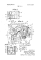
- FIG. 2 is an enlarged side view of one of the switchesof FIG. 1 with a portion of the housing broken away, showing the switch in the contact closed position;
- FIG. 3 is a view similar to that of FIG. 2 showing the switch in the tripped position
- FIG. 4 is a partial sectional view taken along the line 4-4 of FIG.'2;
- FIG. 5 is an enlarged partial sectional view taken along the line 5-5 of FIG. 4;
- Two or more identical switches l0, 10 may be assembled side by side, as by means of rivets or screws which pass through the housings of both switches.
- Each switch may have a housing comprising a plastic molded case 11 and a plastic molded cover 12.
- the elements are mounted in the case 11 and are maintained in place by the cover 12, with the case and cover held together by suitable rivets, fasteners, or screws.
- a fixed contact-13 is mounted on a clip 14 designed to engage a line bus when the switch is inserted into a distribution box.
- a moving contact 15 is mounted on a contact carrier 16.
- a handle 17 is pivotally mounted within the case 11 in a conventional manner, with a portion 18 projecting from the case for manual operation.
- the projection portions 18 of the adjacent switches l0, 10 may be joined by a channel shaped cap member '19 for manual operation of the switches in synchronism.
- a latch 30 is carried in a shaft 31 which pivots in aligned openings 32, 33 in the case 11 and cover 12, respectively.
- a preferred construction for the latch and shaft is illustrated in FIGS. 4 and 5.
- the latch 30 has a T-shaped upper end 36 which is positioned in a slot 37 of the shaft 31. As best seen in FIG. 5, the width of the slot 37 is greater than the thickness of the latch 30, permitting a predetermined amount of pivoting of the latch without producinga corresponding pivoting of the shaft.
- the latch 30 is a metal stamping with a flat surface 38
- the shaft is a plastic molding' with a concave surface at 39 so that the latch and shaft make contact along a line providing minimum resistance to pivoting of the latch.
- each shaft terminates inboard of the exterior of the housing, and a thin wall section 42 (FIG. 4) is provided in the case and in the cover at the shaft pivot opening.
- a link 43 is'positioned in radial slots 44 in the ends of the shafts, so that the shafts move in synchronism.
- the link 43 preferably is push fit into the slots 44 so that there is no play in the coupling.
- a load conductor 50 is positioned in the case 11, with a pressure wire conductor 51 and screw 52 carried at the outer end for clamping a wire to the conductor 50.
- An adjustment screw 53 passes through an opening in the case 11 and threadedly engages the load conductor 50.
- a thermally responsive element in the form of a thermostat metal member 54 is carried at the upper end of the load conductor 50.
- a rigid conductor 55 and a flexible cable 56 provide an electrical circuit between the thermal member 54 and the contact carrier 16.
- the load conductor 50, the latch 30 and the thermostat metal member 54 are generally flat strips and are disposed within the housing with the major portions thereof in parallel spaced relation, with the latch 30 between the load conductor 50 and the thermal member 54 and with the member 54 on the contact side of the group.
- a U-shaped magnet 58 is positioned around the load conductor 50, with the open end of the U adjacent the latch 30, which serves as an armature for the magnet.
- the screw 50 passes through an opening in the magnet 58 and a spring 59 is positioned about the screw between the case and the magnet urging the magnet against the load conductor.
- Another spring 60 is positioned between the latch 30 and load conductor 50 urging the latch to the left as seen in FIG. 2.
- a plurality of arc plates 62 may be mounted in corresponding slots in the case and cover, in spaced relation, three of the arc plates being shown in FIG. 2.
- the are plates have a generally M-shaped configuration (FIG. 7) with a central opening 65 and opposed side openings 66, 67.
- the central opening 65 of the plurality of arc plates define a path for the moving contact as it moves between contact open and contact closed positions.
- the unique shape of the arc plates provides passages and surfaces in close proximity on either side of the center passage defined by the openings 65, so that turbulent cool gas is intermixed with the hot gas comprising the arc plasma. The resulting mixture of gasses is impinged on a maximum of metallic cooling surface further cooling the arc.
- the outer openings 66, 67 in the plates provide uninterrupted vent passages for rapid expansion and expulsion of hot ionized gas from the central portion of the arc chamber to the exhaust vent passage.
- a flange 70 of the trip arm 23 engages a tongue 71 of the latch 30 (FIG. 6).
- the overload tripping mechanism produces tripping of the switch by moving the latch 30 to the right as seen in FIG. 6, so that the trip arm 23 may move downward as seen in FIG. 6.
- the amount of force required to produce tripping is a function of the friction force at the engagement of the flange 70 and tongue 71. This friction force should be low for a sensitive switch and should be uniform in a production run so that all switches will have the same sensitivity.
- One method of obtaining the low and uniform friction force is to perform some hardening and polishing or smoothing working on the parts after manufacture of the part and prior to assembly.
- the trip arm and the latch can be stamped from sheet metal, with the parts designed so' that specific surfaces and edges of the parts serve as the contacting surfaces. More specifically, in stamping a sheet metal part, the dies produce a plastically deformed edge at the surface of entry of the punch and produce a break edge at the surface of entry of the die. The plastically deformed edge is round and smooth while the break edge is sharp and jagged. As illustrated in FIG. 6, the trip am 23 and the latch 30 are stamped sheet metal parts with the plastically deformed edges 72, 73 in engagement and with the break edges 74, 75 spaced from each other. With this arrangement, the desirable low and uniform friction is achieved by having the smooth rounded plastically deformed edges in engagement, without requiring any polishing or working subsequent to the stamping operation.
- the switch operates in the customary manner for closing and opening the contacts.
- the switch is closed by rotating the handle 17 counterclockwise as viewed in FiG. 2, to the position of FIG. 2.
- the switch is opened by rotating the handle 17 clockwise, moving the pivot oint 80 to the left past the center position of the toggle mechanism.
- the spring 26 then completes the opening operation, pivoting the contact carrier 16 counterclockwise about the point 80 and moving the contact 15 away from the contact 13.
- the overload mechanism provides for opening the contacts under certain current conditions. With the contacts closed, the current in the thermal member 54 produces heating and causes the lower end of the member to move to the right. The amount of heating and therefore the amount of motion is a function of the magnitude of current in the member 54. As it moves to the right, the lower end of the thermal member 54 engages the lower end of the latch 30, pivoting the latch counterclockwise. This moves the tongue 71 of the latch away from the flange of the trip arm permitting clockwise motion of the trip arm 23. As the trip arm rotates clockwise, the upper end of the spring 26 moves to the right past the center line of the toggle mechanism and the contact carrier 16 is rotated counterclockwise to the tripped position of FIG. 3.
- the switch may be reset to open condition by rotating the handle 17 to the extreme clockwise position.
- a projection 81 of the handle 17 engages the trip arm 23 at the area 82, rotating the trip arm counterclockwise and lifting the flange 70 above the tongue 71, with the spring 60 urging the latch to the left.
- the switch may also be tripped by a high magnitude current in much less time than is required to heat and deflect the thermal member 54.
- a high intensity current in the load conductor 50 induces a magnetic field in the magnet 58 which attracts the armature latch 30, pivoting the latch counterclockwise and releasing the trip arm.
- the arrangement in the present switch with the thermal member 54 between the latch 30 and the contacts 13, 15 provides an increased distance between the pivot boss 24 of the trip arm 23 and the point of engagement of the trip arm with the latch 30 than would be possible if the positions of the latch and thermal member were reversed as is common practice in other breakers.
- the force holding the contacts 13, 15 together can be made greater while maintaining the desired force at the engagement of the trip arm and latch.
- the increase in contact loading provides an improvement in performance and currentcarrying capacity.
- the maintenance of the low force at the trip arm-latch engagement maintains the desired high sensitivity of the overload mechanism.
- the ratio of contact force to latch force in this type of mechanism is typically a function of distance between the trip arm pivot point and the point of latch and trip arm engagement, and the line of action of the main spring force.
- the magnitude of the contact force is related to the mainspring force.
- the latch force is related to contact force through the mainspring. Breaker performance and reliability are improved if the ratio of contact force to latch force is high.
- the latch 30 and the shaft 31 are dimensioned so that the latch 30 may pivot on the shaft a distance sufficient to permit tripping, before the latch engages the wall of the slot 37.
- the common trip linkage does not produce any loading on the overload mechanism until after the switch has been tripped.
- the continued movement of the trip arm 23 produced by the spring 26 drives the latch further counterclockwise and produces rotation of the shaft 31.
- Shaft rotation in one switch produces a corresponding shaft rotation in an adjacent switch, which in turn rotates the latch of the adjacent switch, releasing the switch arm and tripping the adjacent switch.
- the construction results in low loadings prior to tripping and high torques following tripping.
- An arm 85 may be provided on the trip arm 23 for engaging an arm 86 on the latch after tripping to provide additional force for the rotating torque for common tripping.
- a housing having opposing ends
- a manually movable handle mounted in said housing;
- a trip arm pivotally mounted in said housing adjacent said one end;
- a latch carried in said housing and engaging said trip arm maintaining said trip arm in a set position when said contacts are closed, with said spring urging said trip arm toward a tripped position;
- thermally responsive element connected in circuit between said load conductor and said contact carrier and positioned between said fixed contact and said latch for movement independent of said latch
- a switch as defined in claim 1 including a plurality of arc plates carried in said housing in spaced relation,
- each of said are plates having a generally M-configuration with two outer legs and two center legs defining a central opening between the center legs and spaced outer openings each between an outer leg and a center leg,
- a manually movable handle mounted in said housing;
- a latch carried in said shaft in driving relation, said latch engaging said trip arm maintaining said trip arm in a set position when said contacts are closed, with said spring urging said trip arm toward a tripped position;
- said shaft including means defining a slot for receiving said latch with the size of said slot greater than the size of said latch whereby said latch may move a small distance to release said trip arm without driving said shaft.
- a switch as defined in claim 10 including a plurality of arc plates carried in said housing in spaced relation,
- each of said are plates having a generally M-configuration with a central opening and spaced outer openings
- a switch as defined in claim 5 in which said latch has a first stamped metal plate supporting a secondstamped metal plate of said trip arm when in said set position,
- each of said plates having a plastically deformed edge and a break edge and with the plastically deformed edges contacting each other and with the break edges spaced from each other.
- a manually movable handle mounted in said housing;
- each of said arc plates having a generally M-configuration with two outer legs and two center legs defining a central opening between the center legs and spaced outer openings each between an outer leg and a center a with the central openings of said plurality of plates defining a first path for said moving contact during closing and opening, and with the outer openings defining second and third paths on opposite sides of said first path providing gas flow paths over the inner edge, sides and outer edge of each of said center legs.
- a manually movable handle mounted in said housing;
- a trip arm pivotally mounted in said housing; a spring connected between said contact carrier and said trip arm urging said contact carrier toward said handle; with said handle, contact carrier and spring forming an over center mechanism for closing and opening said contacts; a latch carried in said housing and engaging said trip arm maintaining said trip arm in a set position when said contacts are closed, with said spring urging said trip arm toward a tripped position;
- said latch having a first stamped metal plate supporting a second stamped metal plate of said trip arm when in said set position
- each of said plates having a plastically deformed edge and a break edge and with the plastically deformed edges contacting each other and with the break edges spaced from each other;
- a switch as defined in claim 11 including a plurality of arc plates carried in said housing in spaced relation,
- each of said are plates having a generally M-configuration with a central opening and spaced outer openings
- a housing having opposing ends
- a manually movable handle mounted in said housing;
- a trip arm pivotally mounted in said housing adjacent said one end;
- a latch carried in said housing and engaging said trip arm maintaining said trip arm in a set position when said contacts are closed, with said spring urging said trip arm toward a tripped position;
- thermally responsive element connected in circuit between said load conductor and said contact carrier and positioned between said fixed contact and said latch for movement independent of said latch
- said latch having a first stamped metal plate supporting a second stamped metal plate of said trip arm when in said set position, with each of said plates having a plastically deformed edge and a break edge and with the plastically deformed edges contacting each other and with the break edges spaced from each other.
Abstract
A circuit breaker switch with thermal and magnetic tripping, with the thermal element positioned between the tripping mechanism pivots permitting increased contact force for a given latch load. A common trip for multipole switches with the overload latch and the common trip linkage having a common pivot axis, but independent pivots, with the latch moving freely for a small tripping distance and on moving a greater distance, driving the common trip linkage. An open arc plate design and stamped latch and trip arm having engaging surfaces with smooth plastically deformed edges.
Description
United States Patent Belttary et al. 14 1 June 20, 1972 1541 CIRCUIT BREAKER 3,171,931 3/19'65 Powell ..337 3 [72] Inventors: Harold E. Belttary, West Covina; John G. gfii Palmer Pasadena both ofcalif 1s /l 3,218,418 11/1965 Dorfman etal ....200/l44R 73] i n 11 Electrical products, Los Angeles, 2,360,684 10/1944 Jennings ..335/43 Calif. Primary Evaminer-Bemard A. Gilheany [22] -F1led: April 10, 1970 Assistant Examiner-F. E. Bell [21] APPL NOJ 27,395 Attorney-Harris, Kiech, Russell &. Kern 37 3 6 [57] ABSTRACT 52 U.S.Cl ..3 54 37 4 ,337 71, I J l l 337/] 10 A circuit breaker switch w1th thermal and magnetic tripping, 511 1111. c1. ..H0lh 71/16 with the thermal ripping 58 Field oiSearch .337/54 46 47 48 110 43- "echanism Permmin! incremd a 3 5. 6 4 given latch load. A common trip for multipole switches with the overload latch and the common trip linkage having a com- 56] References Cited mon pivot axis, but independent pivots, with the latch moving freely for a small tripping distance and on moving a greater UNITED STATES NT distance, driving the common trip linkage. An open arc plate design and stamped latch and trip arm having engaging sur- 2,797,277 6/1957 Dorfman et al..... "337/48 faces with Smooth plasticany d f d edgs 2,719,203 9/1955 Geleheiser et a1. ..337/11O 2,81 1,607 10/ l 957 Dorfman et al ..337/48 13 Claims, 7 Drawing Figures maxi CIRCUIT BREAKER This invention relates to circuit breaker switches and certain improvements in the design and construction of such switches. A circuit breaker switch typically has a set of contacts, one fixed and one moving, and a toggle or over center mechanism which is manually operated to close and open the contact. A circuit breaker switch also includes an overload mechanism for tripping the switch and openingthe contacts when the electrical current in the switch exceeds certain conditions. Theswitch may include a thermally responsive element such as a bimetallic member whichfunctions to trip the switch when an overload current exists for a length of time. The switch may also include a magnet and armature arrangement for tripping the switch substantially instantly when a very high current exists.
A variety of circuit breaker switches of the general form described in the preceding paragraphare known in the prior art and many are in use today. Designers are always seeking higher current capacities, improved response to overload, smaller packages, greater reliability, and lower manufacturing cost, and these desirable characteristics present conflicting design problems.
It is an object of the present invention to provide a circuit breaker switch with a new and improved internal arrangement of components which will permit an increase in contact force for the same load at the latch thereby improving the current carrying capacity and performance of the switch. A particular object is to provide a circuit breaker switch with the thermally responsive member positioned between the fixed contact and the overload mechanism, thus providing an increased distance between the trip arm pivot point and the latching point of the trip arm thereby achieving the desired increase in contact force for a given latch load.
It is another object of the invention to provide a circuit breaker switch for common tripping with an adjacent circuit breaker switch incorporating a new improved latch mounting, reducing the number'of parts while maintaining the common tripping characteristic. A particular object is to provide such a switch with the latch and the common trip linkage having a common pivot axis and independent pivots with the latch moving a small distance relative to the common trip linkage for thermal or or magnetic tripping, and then moving a greater distance into engagement with the common tripping linkage to trip the adjacent switch, thereby introducing substantially no load at the latch point due to the common trip connection, while obtaining high trip torque for the second switch after the first switch is tripped.
It is a further object of the invention to provide a circuit breaker switch incorporating a new and improved arc plate construction permitting higher current ratings for a given housing size. A specific object is to provide a plurality of generally M-shaped arc plates defining a central path for a moving contact and additional paths on opposite sides of the first path providing additional cooling surfaces and space for gas expansion and cooling.
It is an additional object of the invention to provide a circuit breaker switch incorporating new and improved stamped metal parts for the engaging elements of the trip arm and latch, utilizing the smooth plastically deformed edges for the engaging surfaces thereby providing minimum latching friction without requiring polishing or other working of the surfaces.
Other objects, advantages, features, and results will more fully appear in the course of the following description. The drawings merely show and the description merely describes a preferred embodiment of the present invention which is given by way of illustration or example.
In the drawings:
FIG. 1 is a top view showing two circuit breaker switches mounted together for common tripping;
FIG. 2 is an enlarged side view of one of the switchesof FIG. 1 with a portion of the housing broken away, showing the switch in the contact closed position;
FIG. 3 is a view similar to that of FIG. 2 showing the switch in the tripped position;
FIG. 4 is a partial sectional view taken along the line 4-4 of FIG.'2;
FIG. 5 is an enlarged partial sectional view taken along the line 5-5 of FIG. 4;
FIG. 6 is an enlarged view of a portion of FIG. 2 showing the engagement of the trip arm and latch; and
FIG. 7 is a partial sectional view taken along the line 77 of FIG. 2.
Two or more identical switches l0, 10 may be assembled side by side, as by means of rivets or screws which pass through the housings of both switches. Each switch may have a housing comprising a plastic molded case 11 and a plastic molded cover 12. In a typical switch, the elements are mounted in the case 11 and are maintained in place by the cover 12, with the case and cover held together by suitable rivets, fasteners, or screws.
A fixed contact-13 is mounted on a clip 14 designed to engage a line bus when the switch is inserted into a distribution box. A moving contact 15 is mounted on a contact carrier 16. A handle 17 is pivotally mounted within the case 11 in a conventional manner, with a portion 18 projecting from the case for manual operation. The projection portions 18 of the adjacent switches l0, 10 may be joined by a channel shaped cap member '19 for manual operation of the switches in synchronism.
The upper. end of the contact carrier 16 is positioned in a slot 22 in the lower end of the handle 17. A trip arm 23 is mounted on a boss 24 in the case 11 for pivoting between the position of FIG. 2 and the position of FIG. 3. A spring 26 has its lower end positioned in an opening in the contact carrier 16 and its upper end positioned in an opening in an upward extension 27 of the trip arm 23.
A latch 30 is carried in a shaft 31 which pivots in aligned openings 32, 33 in the case 11 and cover 12, respectively. A preferred construction for the latch and shaft is illustrated in FIGS. 4 and 5. The latch 30 has a T-shaped upper end 36 which is positioned in a slot 37 of the shaft 31. As best seen in FIG. 5, the width of the slot 37 is greater than the thickness of the latch 30, permitting a predetermined amount of pivoting of the latch without producinga corresponding pivoting of the shaft. In the preferred construction, the latch 30 is a metal stamping with a flat surface 38, and the shaft is a plastic molding' with a concave surface at 39 so that the latch and shaft make contact along a line providing minimum resistance to pivoting of the latch.
Means are provided for coupling the shaft of one switch to the shaft of an adjacent switch. In the preferred embodiment illustrated, each shaft terminates inboard of the exterior of the housing, and a thin wall section 42 (FIG. 4) is provided in the case and in the cover at the shaft pivot opening. When two or more switches are to be mounted side by side, the interior wall sections 42 are removed and a link 43 is'positioned in radial slots 44 in the ends of the shafts, so that the shafts move in synchronism. The link 43 preferably is push fit into the slots 44 so that there is no play in the coupling.
A load conductor 50 is positioned in the case 11, with a pressure wire conductor 51 and screw 52 carried at the outer end for clamping a wire to the conductor 50. An adjustment screw 53 passes through an opening in the case 11 and threadedly engages the load conductor 50. A thermally responsive element in the form of a thermostat metal member 54, typically a bimetallic member, is carried at the upper end of the load conductor 50. A rigid conductor 55 and a flexible cable 56 provide an electrical circuit between the thermal member 54 and the contact carrier 16. The load conductor 50, the latch 30 and the thermostat metal member 54 are generally flat strips and are disposed within the housing with the major portions thereof in parallel spaced relation, with the latch 30 between the load conductor 50 and the thermal member 54 and with the member 54 on the contact side of the group.
A U-shaped magnet 58 is positioned around the load conductor 50, with the open end of the U adjacent the latch 30, which serves as an armature for the magnet. The screw 50 passes through an opening in the magnet 58 and a spring 59 is positioned about the screw between the case and the magnet urging the magnet against the load conductor. Another spring 60 is positioned between the latch 30 and load conductor 50 urging the latch to the left as seen in FIG. 2.
A plurality of arc plates 62 may be mounted in corresponding slots in the case and cover, in spaced relation, three of the arc plates being shown in FIG. 2. The are plates have a generally M-shaped configuration (FIG. 7) with a central opening 65 and opposed side openings 66, 67. The central opening 65 of the plurality of arc plates define a path for the moving contact as it moves between contact open and contact closed positions.
The unique shape of the arc plates provides passages and surfaces in close proximity on either side of the center passage defined by the openings 65, so that turbulent cool gas is intermixed with the hot gas comprising the arc plasma. The resulting mixture of gasses is impinged on a maximum of metallic cooling surface further cooling the arc. The outer openings 66, 67 in the plates provide uninterrupted vent passages for rapid expansion and expulsion of hot ionized gas from the central portion of the arc chamber to the exhaust vent passage.
When the switch is in the closed position, a flange 70 of the trip arm 23 engages a tongue 71 of the latch 30 (FIG. 6). The overload tripping mechanism produces tripping of the switch by moving the latch 30 to the right as seen in FIG. 6, so that the trip arm 23 may move downward as seen in FIG. 6. The amount of force required to produce tripping is a function of the friction force at the engagement of the flange 70 and tongue 71. This friction force should be low for a sensitive switch and should be uniform in a production run so that all switches will have the same sensitivity. One method of obtaining the low and uniform friction force is to perform some hardening and polishing or smoothing working on the parts after manufacture of the part and prior to assembly. The additional smoothing steps of course add to the cost of the finished switch. It has been found that the trip arm and the latch can be stamped from sheet metal, with the parts designed so' that specific surfaces and edges of the parts serve as the contacting surfaces. More specifically, in stamping a sheet metal part, the dies produce a plastically deformed edge at the surface of entry of the punch and produce a break edge at the surface of entry of the die. The plastically deformed edge is round and smooth while the break edge is sharp and jagged. As illustrated in FIG. 6, the trip am 23 and the latch 30 are stamped sheet metal parts with the plastically deformed edges 72, 73 in engagement and with the break edges 74, 75 spaced from each other. With this arrangement, the desirable low and uniform friction is achieved by having the smooth rounded plastically deformed edges in engagement, without requiring any polishing or working subsequent to the stamping operation.
The switch operates in the customary manner for closing and opening the contacts. The switch is closed by rotating the handle 17 counterclockwise as viewed in FiG. 2, to the position of FIG. 2. The switch is opened by rotating the handle 17 clockwise, moving the pivot oint 80 to the left past the center position of the toggle mechanism. The spring 26 then completes the opening operation, pivoting the contact carrier 16 counterclockwise about the point 80 and moving the contact 15 away from the contact 13.
The overload mechanism provides for opening the contacts under certain current conditions. With the contacts closed, the current in the thermal member 54 produces heating and causes the lower end of the member to move to the right. The amount of heating and therefore the amount of motion is a function of the magnitude of current in the member 54. As it moves to the right, the lower end of the thermal member 54 engages the lower end of the latch 30, pivoting the latch counterclockwise. This moves the tongue 71 of the latch away from the flange of the trip arm permitting clockwise motion of the trip arm 23. As the trip arm rotates clockwise, the upper end of the spring 26 moves to the right past the center line of the toggle mechanism and the contact carrier 16 is rotated counterclockwise to the tripped position of FIG. 3. After tripping, the switch may be reset to open condition by rotating the handle 17 to the extreme clockwise position. During resetting, a projection 81 of the handle 17 engages the trip arm 23 at the area 82, rotating the trip arm counterclockwise and lifting the flange 70 above the tongue 71, with the spring 60 urging the latch to the left.
The switch may also be tripped by a high magnitude current in much less time than is required to heat and deflect the thermal member 54. A high intensity current in the load conductor 50 induces a magnetic field in the magnet 58 which attracts the armature latch 30, pivoting the latch counterclockwise and releasing the trip arm.
The arrangement in the present switch with the thermal member 54 between the latch 30 and the contacts 13, 15 provides an increased distance between the pivot boss 24 of the trip arm 23 and the point of engagement of the trip arm with the latch 30 than would be possible if the positions of the latch and thermal member were reversed as is common practice in other breakers. With this configuration, with the thermal member 54 between the trip arm pivot boss 24 and the latch pivot shaft 31, the force holding the contacts 13, 15 together can be made greater while maintaining the desired force at the engagement of the trip arm and latch. The increase in contact loading provides an improvement in performance and currentcarrying capacity. The maintenance of the low force at the trip arm-latch engagement maintains the desired high sensitivity of the overload mechanism. The ratio of contact force to latch force in this type of mechanism is typically a function of distance between the trip arm pivot point and the point of latch and trip arm engagement, and the line of action of the main spring force. The magnitude of the contact force is related to the mainspring force. Thus, the latch force is related to contact force through the mainspring. Breaker performance and reliability are improved if the ratio of contact force to latch force is high.
In the preferred embodiment illustrated, the latch 30 and the shaft 31 are dimensioned so that the latch 30 may pivot on the shaft a distance sufficient to permit tripping, before the latch engages the wall of the slot 37. With this arrangement, the common trip linkage does not produce any loading on the overload mechanism until after the switch has been tripped. After the switch is tripped, the continued movement of the trip arm 23 produced by the spring 26 drives the latch further counterclockwise and produces rotation of the shaft 31. Shaft rotation in one switch produces a corresponding shaft rotation in an adjacent switch, which in turn rotates the latch of the adjacent switch, releasing the switch arm and tripping the adjacent switch. The construction results in low loadings prior to tripping and high torques following tripping.
An arm 85 may be provided on the trip arm 23 for engaging an arm 86 on the latch after tripping to provide additional force for the rotating torque for common tripping.
Although an exemplary embodiment of the invention has been disclosed and discussed, it will be understood that other applications of the invention are possible and that the embodiments disclosed may be subjected to various changes, modifications and substitutions without necessarily departing from the spirit of the invention.
We claim:
1. In a circuit breaker switch, the combination of:
a housing having opposing ends;
a fixed contact mounted in said housing adjacent one of said ends;
a manually movable handle mounted in said housing;
a contact carrier with a moving contact thereon and pivotally engaging said handle;
a trip arm pivotally mounted in said housing adjacent said one end;
a spring connected between said contact carrier and said trip arm urging said contact carrier toward said handle;
with said handle, contact carrier and spring forming an over center mechanism for closing and opening said contacts;
a latch carried in said housing and engaging said trip arm maintaining said trip arm in a set position when said contacts are closed, with said spring urging said trip arm toward a tripped position;
a load conductor mounted in said housing adjacent said other end;
a magnet disposed about said load conductor adjacent said latch;
a thermally responsive element connected in circuit between said load conductor and said contact carrier and positioned between said fixed contact and said latch for movement independent of said latch,
with said responsive element moving under a high current condition to move said latch and release said trip arm for movement to the tripped position opening said contacts, and
with said magnet moving said latch under a high current condition to release said trip arm for movement to the tripped position opening said contacts; and
a shaft pivotally mounted in said housing for driving a corresponding shaft in an adjacent switch, with said latch pivotally mounted in a slot in said shaft in driving relation, with the size of said slot greater than the size of said latch whereby said latch may move a small distance to release said trip arm without driving said shaft.
2. A switch as defined in claim 1 wherein said trip arm and said latch include cooperating members engageable after said latch releases said trip arm, for driving said latch a greater distance to drive said shaft.
3. A switch as defined in claim 1 in which said shaft includes means defining a radial slot in an end thereof, and including a link for positioning in said radial slot and in the radial slot of an adjacent switch for driving the shaft of the switches in synchronism.
4. A switch as defined in claim 1 including a plurality of arc plates carried in said housing in spaced relation,
each of said are plates having a generally M-configuration with two outer legs and two center legs defining a central opening between the center legs and spaced outer openings each between an outer leg and a center leg,
with the central openings of said plurality of plates defining a first path for said moving contact during closing and opening, and with the outer openings defining second and third paths on opposite sides of the first path providing gas flow paths over the inner edge, sides and outer edge of each of said center legs.
5. In a circuit breaker switch, the combination of:
a housing;
a fixed contact mounted in said housing;
a manually movable handle mounted in said housing;
a contact carrier with a moving contact thereon and pivotally engaging said handle;
a trip arm pivotally mounted in said housing;
a spring connected between said contact carrier and said trip arm urging said contact carrier toward said handle;
with said handle, contact carrier and spring forming an over center mechanism for closing and opening said contacts;
a shaft pivotally mounted in said housing for driving a corresponding shaft in an adjacent switch;
a latch carried in said shaft in driving relation, said latch engaging said trip arm maintaining said trip arm in a set position when said contacts are closed, with said spring urging said trip arm toward a tripped position;
a load conductor mounted in said housing;
a magnet disposed about said load conductor adjacent said latch; and
a thermally responsive element connected in circuit between said load conductor and said contact carrier,
with said responsive element moving under a high current condition to move said latch and release said trip arm for movement to the tripped position opening said contacts, and
with said magnet moving said latch under a high current condition to release said trip arm for movement to the tripped position opening said contacts, and
with said shaft including means defining a slot for receiving said latch with the size of said slot greater than the size of said latch whereby said latch may move a small distance to release said trip arm without driving said shaft.
6. A switch as defined in claim 5 wherein said trip arm and said latch include cooperating members engageable after said latch releases said trip arm, for driving said latch a greater distance to drive said shaft.
7. A switch as defined in claim 5 wherein said shalt includes a latch support surface and said latch includes a shaft contact surface, with said shaft supporting said latch at said surfaces and with at least one of said surfaces being convex defining a contact line.
8. A switch as defined in claim 10 includinga plurality of arc plates carried in said housing in spaced relation,
each of said are plates having a generally M-configuration with a central opening and spaced outer openings,
with the central openings of said plurality of plates defining a first path for said moving contact during closing and opening, and with the outer openings defining second and third paths on opposite sides of the first path. 1
9. A switch as defined in claim 5 in which said latch has a first stamped metal plate supporting a secondstamped metal plate of said trip arm when in said set position,
with each of said plates having a plastically deformed edge and a break edge and with the plastically deformed edges contacting each other and with the break edges spaced from each other.
10. In an electrical switch, the combination of:
a housing;
a fixed contact mounted in said housing;
a manually movable handle mounted in said housing;
a contact carrier with a moving contact therein and pivotally engaging said handle;
a trip arm pivotally mounted in said housing; a spring connected between said contact carrier and said trip arm urging said contact carrier toward said handle; with said handle, contact carrier and spring forming an over center mechanism for closing and opening said contacts; a plurality of arc plates carried in said housing in spaced relation, each of said arc plates having a generally M-configuration with two outer legs and two center legs defining a central opening between the center legs and spaced outer openings each between an outer leg and a center a with the central openings of said plurality of plates defining a first path for said moving contact during closing and opening, and with the outer openings defining second and third paths on opposite sides of said first path providing gas flow paths over the inner edge, sides and outer edge of each of said center legs.
11. In a circuit breaker switch, the combination of:
a housing;
a fixed contact mounted in said housing;
a manually movable handle mounted in said housing;
a contact carrier with a moving contact therein and pivotally engaging said handle;
a trip arm pivotally mounted in said housing; a spring connected between said contact carrier and said trip arm urging said contact carrier toward said handle; with said handle, contact carrier and spring forming an over center mechanism for closing and opening said contacts; a latch carried in said housing and engaging said trip arm maintaining said trip arm in a set position when said contacts are closed, with said spring urging said trip arm toward a tripped position;
said latch having a first stamped metal plate supporting a second stamped metal plate of said trip arm when in said set position,
with each of said plates having a plastically deformed edge and a break edge and with the plastically deformed edges contacting each other and with the break edges spaced from each other;
a load conductor mounted in said housing;
a magnet disposed about said load conductor adjacent said latch; and
a thermally responsive element connected in circuit between said load conductor and said contact carrier,
with said responsive element moving under a high current condition to move said latch and release said trip arm for movement to the tripped position opening said contacts, and
with said magnet moving said latch under a high current condition to release said trip arm for movement to the tripped position opening said contacts.
12. A switch as defined in claim 11 including a plurality of arc plates carried in said housing in spaced relation,
each of said are plates having a generally M-configuration with a central opening and spaced outer openings,
with the central openings of said plurality of plates defining a first path for said moving contact during closing and opening, and with the outer openings defining second and third paths on opposite sides of the first path.
13. In a circuit breaker switch, the combination of:
a housing having opposing ends;
a fixed contact mounted in said housing adjacent one of said ends;
a manually movable handle mounted in said housing;
a contact carrier with a moving contact thereon and pivotally engaging said handle;
a trip arm pivotally mounted in said housing adjacent said one end;
a spring connected contact said contact carrier and said trip arm urging said contact carrier toward said handle;
with said handle, contact carrier and spring forming an over center mechanism for closing and opening said contacts;
a latch carried in said housing and engaging said trip arm maintaining said trip arm in a set position when said contacts are closed, with said spring urging said trip arm toward a tripped position;
a load conductor mounted in said housing adjacent said latch;
a magnet disposed about said load conductor adjacent said latch;
a thermally responsive element connected in circuit between said load conductor and said contact carrier and positioned between said fixed contact and said latch for movement independent of said latch,
with said responsive element moving under a high current condition to move said latch and release said trip arm for movement to the tripped position opening said contacts,
and
with said magnet moving said latch under a high current condition to release said trip arm for movement to the tripped position opening said contacts,
with said latch having a first stamped metal plate supporting a second stamped metal plate of said trip arm when in said set position, with each of said plates having a plastically deformed edge and a break edge and with the plastically deformed edges contacting each other and with the break edges spaced from each other.
Claims (13)
1. In a circuit breaker switch, the combination of: a housing having opposing ends; a fixed contact mounted in said housing adjacent one of said ends; a manually movable handle mounted in said housing; a contact carrier with a moving contact thereon and pivotally engaging said handle; a trip arm pivotally mounted in said housing adjacent said one end; a spring connected between said contact carrier and said trip arm urging said contact carrier toward said handle; with said handle, contact carrier and spring forming an over center mechanism for closing and opening said contacts; a latch carried in said housing and engaging said trip arm maintaining said trip arm in a set position when said contacts are closed, with said spring urging said trip arm toward a tripped position; a load conductor mounted in said housing adjacent said other end; a magnet disposed about said load conductor adjacent said latch; a thermally responsive element connected in circuit between said load conductor and said contact carrier and positioned between said fixed contact and said latch for movement independent of said latch, with said responsive element moving under a high current condition to move said latch and release said trip arm for movement to the tripped position opening said contacts, and with said magnet moving said latch under a high current condition to release said trip arm for movement to the tripped position opening said contacts; and a shaft pivotally mounted in said housing for driving a corresponding shaft in an adjacent switch, with said latch pivotally mounted in a slot in said shaft in driving relation, with the size of said slot greater than the size of said latch whereby said latch may move a small distance to release said trip arm without driving said shaft.
2. A switch as defined in claim 1 wherein said trip arm and said latch include cooperating members engageable after said latch releases said trip arm, for driving said latch a greater distance to drive said shaft.
3. A switch as defined in claim 1 in which said shaft includes means defining a radial slot in an end thereof, and including a link for positioning in said radial slot and in the radial slot of an adjacent switch for driving the shaft of the switches in synchronism.
4. A switch as defined in claim 1 including a plurality of arc plates carried in said housing in spaced relation, each of said arc plates having a generally M-configuration with two outEr legs and two center legs defining a central opening between the center legs and spaced outer openings each between an outer leg and a center leg, with the central openings of said plurality of plates defining a first path for said moving contact during closing and opening, and with the outer openings defining second and third paths on opposite sides of the first path providing gas flow paths over the inner edge, sides and outer edge of each of said center legs.
5. In a circuit breaker switch, the combination of: a housing; a fixed contact mounted in said housing; a manually movable handle mounted in said housing; a contact carrier with a moving contact thereon and pivotally engaging said handle; a trip arm pivotally mounted in said housing; a spring connected between said contact carrier and said trip arm urging said contact carrier toward said handle; with said handle, contact carrier and spring forming an over center mechanism for closing and opening said contacts; a shaft pivotally mounted in said housing for driving a corresponding shaft in an adjacent switch; a latch carried in said shaft in driving relation, said latch engaging said trip arm maintaining said trip arm in a set position when said contacts are closed, with said spring urging said trip arm toward a tripped position; a load conductor mounted in said housing; a magnet disposed about said load conductor adjacent said latch; and a thermally responsive element connected in circuit between said load conductor and said contact carrier, with said responsive element moving under a high current condition to move said latch and release said trip arm for movement to the tripped position opening said contacts, and with said magnet moving said latch under a high current condition to release said trip arm for movement to the tripped position opening said contacts, and with said shaft including means defining a slot for receiving said latch with the size of said slot greater than the size of said latch whereby said latch may move a small distance to release said trip arm without driving said shaft.
6. A switch as defined in claim 5 wherein said trip arm and said latch include cooperating members engageable after said latch releases said trip arm, for driving said latch a greater distance to drive said shaft.
7. A switch as defined in claim 5 wherein said shaft includes a latch support surface and said latch includes a shaft contact surface, with said shaft supporting said latch at said surfaces and with at least one of said surfaces being convex defining a contact line.
8. A switch as defined in claim 10 including a plurality of arc plates carried in said housing in spaced relation, each of said arc plates having a generally M-configuration with a central opening and spaced outer openings, with the central openings of said plurality of plates defining a first path for said moving contact during closing and opening, and with the outer openings defining second and third paths on opposite sides of the first path.
9. A switch as defined in claim 5 in which said latch has a first stamped metal plate supporting a second stamped metal plate of said trip arm when in said set position, with each of said plates having a plastically deformed edge and a break edge and with the plastically deformed edges contacting each other and with the break edges spaced from each other.
10. In an electrical switch, the combination of: a housing; a fixed contact mounted in said housing; a manually movable handle mounted in said housing; a contact carrier with a moving contact therein and pivotally engaging said handle; a trip arm pivotally mounted in said housing; a spring connected between said contact carrier and said trip arm urging said contact carrier toward said handle; with said handle, contact carrier and spring forming an over center mechanism for closing and opening said conTacts; a plurality of arc plates carried in said housing in spaced relation, each of said arc plates having a generally M-configuration with two outer legs and two center legs defining a central opening between the center legs and spaced outer openings each between an outer leg and a center leg, with the central openings of said plurality of plates defining a first path for said moving contact during closing and opening, and with the outer openings defining second and third paths on opposite sides of said first path providing gas flow paths over the inner edge, sides and outer edge of each of said center legs.
11. In a circuit breaker switch, the combination of: a housing; a fixed contact mounted in said housing; a manually movable handle mounted in said housing; a contact carrier with a moving contact therein and pivotally engaging said handle; a trip arm pivotally mounted in said housing; a spring connected between said contact carrier and said trip arm urging said contact carrier toward said handle; with said handle, contact carrier and spring forming an over center mechanism for closing and opening said contacts; a latch carried in said housing and engaging said trip arm maintaining said trip arm in a set position when said contacts are closed, with said spring urging said trip arm toward a tripped position; said latch having a first stamped metal plate supporting a second stamped metal plate of said trip arm when in said set position, with each of said plates having a plastically deformed edge and a break edge and with the plastically deformed edges contacting each other and with the break edges spaced from each other; a load conductor mounted in said housing; a magnet disposed about said load conductor adjacent said latch; and a thermally responsive element connected in circuit between said load conductor and said contact carrier, with said responsive element moving under a high current condition to move said latch and release said trip arm for movement to the tripped position opening said contacts, and with said magnet moving said latch under a high current condition to release said trip arm for movement to the tripped position opening said contacts.
12. A switch as defined in claim 11 including a plurality of arc plates carried in said housing in spaced relation, each of said arc plates having a generally M-configuration with a central opening and spaced outer openings, with the central openings of said plurality of plates defining a first path for said moving contact during closing and opening, and with the outer openings defining second and third paths on opposite sides of the first path.
13. In a circuit breaker switch, the combination of: a housing having opposing ends; a fixed contact mounted in said housing adjacent one of said ends; a manually movable handle mounted in said housing; a contact carrier with a moving contact thereon and pivotally engaging said handle; a trip arm pivotally mounted in said housing adjacent said one end; a spring connected contact said contact carrier and said trip arm urging said contact carrier toward said handle; with said handle, contact carrier and spring forming an over center mechanism for closing and opening said contacts; a latch carried in said housing and engaging said trip arm maintaining said trip arm in a set position when said contacts are closed, with said spring urging said trip arm toward a tripped position; a load conductor mounted in said housing adjacent said latch; a magnet disposed about said load conductor adjacent said latch; a thermally responsive element connected in circuit between said load conductor and said contact carrier and positioned between said fixed contact and said latch for movement independent of said latch, with said responsive element moving under a high current condition to move said latch and release said trip arm foR movement to the tripped position opening said contacts, and with said magnet moving said latch under a high current condition to release said trip arm for movement to the tripped position opening said contacts, with said latch having a first stamped metal plate supporting a second stamped metal plate of said trip arm when in said set position, with each of said plates having a plastically deformed edge and a break edge and with the plastically deformed edges contacting each other and with the break edges spaced from each other.
Applications Claiming Priority (1)
| Application Number | Priority Date | Filing Date | Title |
|---|---|---|---|
| US2739570A | 1970-04-10 | 1970-04-10 |
Publications (1)
| Publication Number | Publication Date |
|---|---|
| US3671908A true US3671908A (en) | 1972-06-20 |
Family
ID=21837487
Family Applications (1)
| Application Number | Title | Priority Date | Filing Date |
|---|---|---|---|
| US27395A Expired - Lifetime US3671908A (en) | 1970-04-10 | 1970-04-10 | Circuit breaker |
Country Status (1)
| Country | Link |
|---|---|
| US (1) | US3671908A (en) |
Cited By (4)
| Publication number | Priority date | Publication date | Assignee | Title |
|---|---|---|---|---|
| EP0004508A2 (en) * | 1978-03-22 | 1979-10-03 | Legrand | Circuit breaker with a movable latching element urged by elastic return means |
| US4231006A (en) * | 1979-03-26 | 1980-10-28 | Sylvania Circuit Breaker Corporation | Circuit breaker having a thermally responsive latching member |
| GB2176056A (en) * | 1983-04-20 | 1986-12-10 | Airpax Corp | Circuit breaker |
| WO1998002897A1 (en) * | 1996-07-15 | 1998-01-22 | Gewiss S.P.A. | Kinematic device for actuating the moving contact, particularly for automatic electric breakers |
Citations (8)
| Publication number | Priority date | Publication date | Assignee | Title |
|---|---|---|---|---|
| US2360684A (en) * | 1941-10-30 | 1944-10-17 | Westinghouse Electric & Mfg Co | Circuit breaker |
| US2691711A (en) * | 1951-03-08 | 1954-10-12 | Westinghouse Electric Corp | Arc-quenching device for electric contactors |
| US2719203A (en) * | 1952-05-02 | 1955-09-27 | Westinghouse Electric Corp | Circuit breakers |
| US2797277A (en) * | 1954-09-24 | 1957-06-25 | Westinghouse Electric Corp | Circuit breaker |
| US2811607A (en) * | 1954-02-19 | 1957-10-29 | Westinghouse Electric Corp | Circuit breaker |
| US2962569A (en) * | 1954-10-28 | 1960-11-29 | Westinghouse Electric Corp | Circuit breaker |
| US3171931A (en) * | 1963-03-28 | 1965-03-02 | Gen Electric | Multiple electric circuit breaker with common trip bar |
| US3218418A (en) * | 1961-05-19 | 1965-11-16 | Westinghouse Electric Corp | Circuit breaker with arc-extinguishing means |
-
1970
- 1970-04-10 US US27395A patent/US3671908A/en not_active Expired - Lifetime
Patent Citations (8)
| Publication number | Priority date | Publication date | Assignee | Title |
|---|---|---|---|---|
| US2360684A (en) * | 1941-10-30 | 1944-10-17 | Westinghouse Electric & Mfg Co | Circuit breaker |
| US2691711A (en) * | 1951-03-08 | 1954-10-12 | Westinghouse Electric Corp | Arc-quenching device for electric contactors |
| US2719203A (en) * | 1952-05-02 | 1955-09-27 | Westinghouse Electric Corp | Circuit breakers |
| US2811607A (en) * | 1954-02-19 | 1957-10-29 | Westinghouse Electric Corp | Circuit breaker |
| US2797277A (en) * | 1954-09-24 | 1957-06-25 | Westinghouse Electric Corp | Circuit breaker |
| US2962569A (en) * | 1954-10-28 | 1960-11-29 | Westinghouse Electric Corp | Circuit breaker |
| US3218418A (en) * | 1961-05-19 | 1965-11-16 | Westinghouse Electric Corp | Circuit breaker with arc-extinguishing means |
| US3171931A (en) * | 1963-03-28 | 1965-03-02 | Gen Electric | Multiple electric circuit breaker with common trip bar |
Cited By (6)
| Publication number | Priority date | Publication date | Assignee | Title |
|---|---|---|---|---|
| EP0004508A2 (en) * | 1978-03-22 | 1979-10-03 | Legrand | Circuit breaker with a movable latching element urged by elastic return means |
| FR2420839A1 (en) * | 1978-03-22 | 1979-10-19 | Legrand Sa | CIRCUIT BREAKER, ITS TRIP MECHANISM |
| EP0004508A3 (en) * | 1978-03-22 | 1979-10-31 | Legrand Societe Anonyme | Circuit breaker with a movable latching element urged by elastic return means |
| US4231006A (en) * | 1979-03-26 | 1980-10-28 | Sylvania Circuit Breaker Corporation | Circuit breaker having a thermally responsive latching member |
| GB2176056A (en) * | 1983-04-20 | 1986-12-10 | Airpax Corp | Circuit breaker |
| WO1998002897A1 (en) * | 1996-07-15 | 1998-01-22 | Gewiss S.P.A. | Kinematic device for actuating the moving contact, particularly for automatic electric breakers |
Similar Documents
| Publication | Publication Date | Title |
|---|---|---|
| US3950714A (en) | Self-adjusting circuit breaker with rotating trip assembly | |
| US2214695A (en) | Circuit breaker | |
| US4516098A (en) | Overcurrent protection switch | |
| US3408466A (en) | Circuit interrupter with locking provision | |
| US2692926A (en) | Multipole circuit breaker | |
| US2293179A (en) | Circuit breaker | |
| US3200217A (en) | Circuit breaker with thermal and magnetic trip means | |
| US3671908A (en) | Circuit breaker | |
| US2875289A (en) | Two pole circuit breaker | |
| US2300530A (en) | Circuit breaker | |
| US3317867A (en) | Electric circuit breaker with thermalmagnetic tripping allowing for overtravel of the thermal means | |
| US2462244A (en) | Circuit breaker | |
| US4092623A (en) | Circuit breaker | |
| US3305806A (en) | Automatically resettable circuit breaker having two serially connected toggles | |
| GB1407067A (en) | Circuit breakers | |
| US2325650A (en) | Circuit breaker | |
| US3088008A (en) | Circuit breaker | |
| US3005066A (en) | Circuit breaker | |
| US2813946A (en) | Circuit breakers | |
| US2806103A (en) | Circuit breaker | |
| US4047134A (en) | Circuit breaker | |
| US2660643A (en) | Circuit breaker | |
| US3467920A (en) | Molded case circuit breaker with sensitive thermal and magnetic trip mechanism | |
| US2321603A (en) | Circuit breaker | |
| US3211861A (en) | Circuit interrupter having an improved tripping mechanism with an adjusting structure that cooperates with a bimetal to enhance tripping movement |
Legal Events
| Date | Code | Title | Description |
|---|---|---|---|
| AS | Assignment |
Owner name: COMMANDER ELECTRICAL EQUIPMENT, INC., 950 WARDEN A Free format text: ASSIGNMENT OF ASSIGNORS INTEREST.;ASSIGNOR:GTE PRODUCTS CORPORATION;REEL/FRAME:004211/0085 Effective date: 19831130 Owner name: CHALLENGER CARIBBEAN CORPORATION, P.O. BOX AF, CAN Free format text: ASSIGNMENT OF ASSIGNORS INTEREST.;ASSIGNOR:GTE PRODUCTS CORPORATION;REEL/FRAME:004211/0085 Effective date: 19831130 |