US3649829A - Laminar flow cell - Google Patents
Laminar flow cell Download PDFInfo
- Publication number
- US3649829A US3649829A US78427A US3649829DA US3649829A US 3649829 A US3649829 A US 3649829A US 78427 A US78427 A US 78427A US 3649829D A US3649829D A US 3649829DA US 3649829 A US3649829 A US 3649829A
- Authority
- US
- United States
- Prior art keywords
- laminar flow
- conduit
- fluid
- sample
- section
- Prior art date
- Legal status (The legal status is an assumption and is not a legal conclusion. Google has not performed a legal analysis and makes no representation as to the accuracy of the status listed.)
- Expired - Lifetime
Links
- 239000012530 fluid Substances 0.000 claims abstract description 104
- 230000005855 radiation Effects 0.000 claims abstract description 14
- 238000012544 monitoring process Methods 0.000 claims description 35
- 239000007788 liquid Substances 0.000 claims description 12
- 238000000034 method Methods 0.000 claims description 12
- 230000002285 radioactive effect Effects 0.000 claims description 9
- 230000035945 sensitivity Effects 0.000 claims description 8
- 238000011109 contamination Methods 0.000 abstract description 9
- 239000012857 radioactive material Substances 0.000 abstract description 2
- 239000000523 sample Substances 0.000 description 55
- 230000000694 effects Effects 0.000 description 5
- 239000007789 gas Substances 0.000 description 5
- GRYLNZFGIOXLOG-UHFFFAOYSA-N Nitric acid Chemical compound O[N+]([O-])=O GRYLNZFGIOXLOG-UHFFFAOYSA-N 0.000 description 4
- 239000000463 material Substances 0.000 description 4
- 239000000975 dye Substances 0.000 description 3
- 229910017604 nitric acid Inorganic materials 0.000 description 3
- XLYOFNOQVPJJNP-UHFFFAOYSA-N water Chemical compound O XLYOFNOQVPJJNP-UHFFFAOYSA-N 0.000 description 3
- 230000001276 controlling effect Effects 0.000 description 2
- 238000002347 injection Methods 0.000 description 2
- 239000007924 injection Substances 0.000 description 2
- 238000010926 purge Methods 0.000 description 2
- 230000001105 regulatory effect Effects 0.000 description 2
- 239000012780 transparent material Substances 0.000 description 2
- 229910052778 Plutonium Inorganic materials 0.000 description 1
- KJTLSVCANCCWHF-UHFFFAOYSA-N Ruthenium Chemical compound [Ru] KJTLSVCANCCWHF-UHFFFAOYSA-N 0.000 description 1
- 230000004913 activation Effects 0.000 description 1
- 238000006243 chemical reaction Methods 0.000 description 1
- 238000004140 cleaning Methods 0.000 description 1
- 238000010276 construction Methods 0.000 description 1
- 238000010586 diagram Methods 0.000 description 1
- 239000012153 distilled water Substances 0.000 description 1
- 239000011521 glass Substances 0.000 description 1
- 230000002452 interceptive effect Effects 0.000 description 1
- 238000005259 measurement Methods 0.000 description 1
- 238000000465 moulding Methods 0.000 description 1
- GFUGMBIZUXZOAF-UHFFFAOYSA-N niobium zirconium Chemical compound [Zr].[Nb] GFUGMBIZUXZOAF-UHFFFAOYSA-N 0.000 description 1
- 239000002245 particle Substances 0.000 description 1
- OYEHPCDNVJXUIW-UHFFFAOYSA-N plutonium atom Chemical compound [Pu] OYEHPCDNVJXUIW-UHFFFAOYSA-N 0.000 description 1
- 238000011084 recovery Methods 0.000 description 1
- 229910052707 ruthenium Inorganic materials 0.000 description 1
- 239000012488 sample solution Substances 0.000 description 1
- 238000000926 separation method Methods 0.000 description 1
- 239000000243 solution Substances 0.000 description 1
- 239000000126 substance Substances 0.000 description 1
- 238000013022 venting Methods 0.000 description 1
Images
Classifications
-
- G—PHYSICS
- G01—MEASURING; TESTING
- G01T—MEASUREMENT OF NUCLEAR OR X-RADIATION
- G01T7/00—Details of radiation-measuring instruments
- G01T7/02—Collecting means for receiving or storing samples to be investigated and possibly directly transporting the samples to the measuring arrangement; particularly for investigating radioactive fluids
-
- F—MECHANICAL ENGINEERING; LIGHTING; HEATING; WEAPONS; BLASTING
- F16—ENGINEERING ELEMENTS AND UNITS; GENERAL MEASURES FOR PRODUCING AND MAINTAINING EFFECTIVE FUNCTIONING OF MACHINES OR INSTALLATIONS; THERMAL INSULATION IN GENERAL
- F16L—PIPES; JOINTS OR FITTINGS FOR PIPES; SUPPORTS FOR PIPES, CABLES OR PROTECTIVE TUBING; MEANS FOR THERMAL INSULATION IN GENERAL
- F16L58/00—Protection of pipes or pipe fittings against corrosion or incrustation
-
- G—PHYSICS
- G01—MEASURING; TESTING
- G01N—INVESTIGATING OR ANALYSING MATERIALS BY DETERMINING THEIR CHEMICAL OR PHYSICAL PROPERTIES
- G01N21/00—Investigating or analysing materials by the use of optical means, i.e. using sub-millimetre waves, infrared, visible or ultraviolet light
- G01N21/01—Arrangements or apparatus for facilitating the optical investigation
- G01N21/03—Cuvette constructions
- G01N21/05—Flow-through cuvettes
-
- G—PHYSICS
- G01—MEASURING; TESTING
- G01N—INVESTIGATING OR ANALYSING MATERIALS BY DETERMINING THEIR CHEMICAL OR PHYSICAL PROPERTIES
- G01N35/00—Automatic analysis not limited to methods or materials provided for in any single one of groups G01N1/00 - G01N33/00; Handling materials therefor
- G01N35/10—Devices for transferring samples or any liquids to, in, or from, the analysis apparatus, e.g. suction devices, injection devices
- G01N35/1095—Devices for transferring samples or any liquids to, in, or from, the analysis apparatus, e.g. suction devices, injection devices for supplying the samples to flow-through analysers
Definitions
- sample fluid containing. for example, oa e a i 250/31 1" is made to flow as an integral core within a column of inert 511 Int. Cl. ..G0ln 23/12 fluid thmngh the sensitive zone of a monitor such as a radia- [58 1 Field of Search ..250/43.5 FC, 43.5 MR, 43.5 R, non detector-
- the inert fluid acts as a sheath to Prevent tamination of stationary surfaces within the sensitive zone.
- Sample fluid is injected into the flow of inert fluid with a minimum of turbulence and mixing.
- the present invention relates to the monitoring of a flowing sample fluid where it is desirable to prevent contamination of surfaces within a sensitive zone by the sample.
- radioactive fluid samples that are passed through or near a radiation detector can deposit radioactive material on surfaces within the sensitive zone of the detector. This radioactive contamination if not removed can result in erroneous subsequent readings. Also in the colorimetric examination of fluid dyes passing through a portion of transparent conduit, contamination of the conduit surfaces can prevent determination ofthe actual color oflater dye samples.
- the invention is particularly applicable to the monitoring of liquid samples, but may also be used for gas sample monitoring.
- One application related to the principles of the present invention in respect to gases is disclosed in the assignees copending US Pat. application Ser. No. 78,538, filed Oct. 6, 1970.
- a flow of sample fluid is entrained as a parallel flowing integral core within a flowing column of buffer or inert fluid. Both fluids are maintained at laminar flow rates to prevent mixing while passing through the sensitive zone of a monitoring instrument such as a radiation detector or colorimeter.
- a laminar flow cell including an outer conduit for the inert fluid flow.
- An inner conduit is disposed within the outer conduit for injecting the sample fluid flow into a flowing column of inert fluid.
- the outer conduit includes an initial straight section followed by a converging section, and an elongated section of reduced diameter.
- the inner conduit includes an initial straight section and terminates with a converging section within the converging section of the outer conduit without entering the elongated section.
- a monitoring instrument is disposed with its sensitive zone encompassing the elongated section of the outer conduit. The sample fluid is accelerated within the inner conduit converging section with inwardly directed velocity and is thereby maintained as an integral core surrounded by inert fluid through the elongated section. Since the sample fluid does not contact any stationary surfaces within the sensitive zone of the monitoring instrument, the possibility of contaminating sample material adhering and remaining within the sensitive zone is minimized. Consequently, the monitoring instrument can accurately detect the characteristics, such as radioactivity or color of the sample fluid.
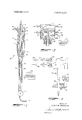
- FIG. 1 is a view in cross section of a preferred embodiment of a laminar flow cell.
- FIG. 2 is a fragmentary view partially in cross section of another embodiment of a laminar flow cell.
- FIG. 3 is a schematic diagram of a continuous gamma activity monitor employing a laminar flow cell of the present invention.
- a laminar flow cell 10 having an outer conduit 11 with an inlet 13 for introducing a bufler or inert fluid 15.
- An inner conduit 17 with sample inlet 19 for admitting a sample fluid 21 is shown coaxially disposed within conduit 11.
- Both outer conduit 11 and inner conduit 17 have sufficiently long straight sections 12 and 18 respectively following their inlets 13 and 19 to allow initial inlet turbulence to subside.
- a nozzle or converging section 23 is provided in the outer conduit 11 following straight section 12 for molding the flow of inert fluid 15 into a fluid sheath 29.
- Inner conduit 17 is terminated with a nozzle or converging section 25, concentrically disposed within converging section 23.
- Converging section 25 inwardly directs the sample fluid flow into an integral core 27 within fluid sheath 29.
- An elongated outer conduit section 31 of reduced diameter is coupled to the smaller or reduced diameter of converging section 23 to contain the flowing inert fluid sheath 29 with the enclosed integral sample core 27 flowing parallel to sheath 29.
- a flow control valve 33 is installed at the end of elongated conduit section 31 opposite converging section 23 for regulating the flow at laminar rates.
- a suitable monitoring instrument 35 is disposed adjacent or proximate to elongated section 31 such that the sensitive zone of instrument 35 does not encompass any sections of the laminar flow cell other than the elongated section 31.
- Monitoring instrument 35 can be any of various radiation detectors or colorimetric instruments well known in the art depending on the specific application of the laminar flow cell.
- laminar flow cell I0 Although the flow of fluids within laminar flow cell I0 are shown entering at the top and leaving from the bottom, the orientation of the cell can be reversed with inlets l3 and 19 disposed at the bottom and elongated section 31 towards the top to provide an upward flow through the cell. An upward flow would more readily remove entrained gases from elongated section 31.
- the materials used in constructing the flow cell 10 depend on the particular fluids and monitoring techniques employed. For instance a transparent material such as glass is required especially in elongated section 31 for colorimetric determinations. In like manner, it may be desirable to add dye to a radioactive sample fluid to ascertain whether or not the sample remains as an integral core, and in this respect transparent materials could be of value in constructing a laminar flow cell for radiation monitoring. Equally important in the construc tion of a cell used in radiation monitoring, is the selection of materials that will not be activated by decay particles from the sample to produce interfering radiation. Such materials can be selected using known principles of nuclear activation reactions.
- inert fluid 15 A number of substances can be selected for use as inert fluid 15.
- the density and viscosity should be matched as close as possible to the sample fluid. If both the sample and inert fluids are liquid rather than gases, density and viscosity variations with temperature will not be as great and better performance can be expected from he laminar flow cell.
- the inert fluids forming sheath 29 should be transparent. For radiation measurements a nonradioactive or radio-inert fluid is preferred. Distilled water might often be chosen for use in either of these type monitoring systems.
- the Reynolds number of both fluids should be between 100 to 1,000 within elongated section 31.
- the optimum range of Reynolds numbers is between 400 and 500 since higher numbers may result in some turbulence and lower velocities or numbers may permit density and temperature disturbances to reach the conduit walls.
- turbulence Another possible source of turbulence is from the injection of the sample fluid into the inert fluid flow. If the density and viscosity of the two fluids are nearly the same the turbulence at the point of injection is not so great. However, if the densities and viscosities are not matched within about 1 percent, the streamlined nozzles or converging sections 23 and 25 have increased relevance in preventing instability. Converging sections 23 and 25 that have a reduction to about one-half their original or maximum inside diameters along a length of one to three maximum inside diameters have performed satisfactorily with fluids having densities and viscosities matched within about 1 to 10 percent. Where the fluids are matched to within about 1 percent in respect to density and viscosity, straight concentric tubes without converging sections can be used to inject an integral core of one fluid into another.
- the overall length of laminar flow cell 10 should be at least about 20 times the maximum inside diameter of the outer conduit lI.
- Elongated section 3l should be about one-third to one-half the length of the laminar flow cell.
- satisfactory laminar flow cells can have maximum inside diameters of about 0.4 to 5 centimeters and lengths of about to 200 centimeters.
- Cells of the type shown and described in conjunction with FIG. 1 have been found to be stable over a 10 to 1 range of flow rates when the sample and inert fluids are closely matched in density and viscosity. Through use of different size cells, integral cores of sample fluid with diameters of about 0.2 centimeters to 1.5 centimeters have been obtained over lengths of5 to 100 centimeters.
- FIG. 2 Another embodiment of the present invention is shown in FIG. 2.
- Sample liquid 40 is shown entering a vent chamber 41 having an overflow outlet 43. Entrained gases which might otherwise interfere with monitoring of a liquid sample can be removed through outlet 43.
- vent chamber 45 receives inert liquid 46 and permits venting and overflow through outlet 47.
- Conductivity probes 49 sense the level of liquid in chamber 45 and can be used to control the flow of the sample or the inert liquid with fluid flow controller 51 and suitable valves (not shown in FIG. 2) within the liquid feedlines.
- Chambers 41 and 45 are connected to inner conduit 53 and outer conduit 55 respectively to pass the contained liquids through converging sections similar to those at 23 and 25 shown in FIG. 1. By maintaining a constant small head of liquid in chambers 41 and 45, laminar flow is obtained through an elongated section similar to that shown at 31 in FIG. 1 for monitoring the sample fluid.
- a scintillation probe 59 used as a radiation monitor is disposed within a housing of shielding material 61 adjacent the elongated section 63 of laminar flow cell 57.
- a count rate meter 60 receives and counts the output from probe 59.
- a solenoid valve 65 admits a sample of radioactive fluid to a pressure regulating valve 67 and a flow meter 69 for controlling and monitoring the sample flow. The sample flow is introduced into the laminar flow cell 57 through a chamber 58.
- the inert fluid flow is similarly admitted through valve 66 and controlled with pressure regulator 71 and flow meter 73 before entering the laminar flow cell 57 by way of chamber 75.
- Overflow lines 77 and 79 vent chambers 58 and 75 respectively to remove entrained air and provide overflow if either fluid is introduced at too great a rate.
- Conductivity probes as shown in FIG. 2 at 49 can be used to control solenoid valve 65 to shut off sample flow if the inert fluid flow rate moves above or below a safe operating range.
- the continuous gamma activity monitor of FIG. 3 can be operated with a sample flow of about 70 cubic centimeters per minute of radioactive nitric acid solution used in a plutonium separation process.
- a water flow of about 900 cubic centimeters per minute serves as a buffer or radio-inert fluid to isolate the contaminated nitric acid within the laminar flow cell.
- Pressure regulator 67 and 71 maintain constant flow of nitric acid and water to within about 5 percent under varying supply pressures.
- Nitric acid sample solutions of zirconium niobium -95 and ruthenium -l03 with activities of up to 10 disintergrations per minute per milliliter have been passed through the laminar flow cell with recovery to normal background count level after about 10 minutes.
- This invention provides a method of monitoring a sample fluid with such as a radiation detector while preventing sample material from contaminating surfaces within range of the detector. Also a laminar flow cell is provided for maintaining a sample fluid flow apart from conduit walls by enclosing the sample within a sheath of inert fluid flow.
- the invention is applicable, not only to radiation monitoring but also to colorimetric or other monitoring where residual sample within range of the monitoring instrument could give misleading results.
- Method of monitoring a flowing sample fluid with a monitoring instrument having a zone ofsensitivity comprising:
- a laminar flow cell for use in combination with a monitoring instrument that includes a zone of sensitivity comprismg:
- an outer conduit having 1. a converging section including an initial and a reduced diameter disposed outside said zone of sensitivity,
- said introducing means includes a pressure regulator and flow meter for maintaining laminar flow rates in both said sample and inert fluid flow.
- monitoring 5 instrument comprises a radiation detector for monitoring a radioactive sample fluid within a sheath of radio-inert fluid.
Abstract
A sample fluid, containing, for example, radioactive material, is made to flow as an integral core within a column of inert fluid through the sensitive zone of a monitor such as a radiation detector. The inert fluid acts as a sheath to prevent contamination of stationary surfaces within the sensitive zone. Sample fluid is injected into the flow of inert fluid with a minimum of turbulence and mixing.
Description
Elited States Patent Randolph 5] Mar. M, 1972 [54] LAMINAR FLOW CELL [56] References Cited [72] Inventor: Henry W. Randolph, Belvedere, S.C. UNITED STATES PATENTS [73] Assignee: The United States of America as 3,238,367 3/1966 Stemberg et al ..250/43.5 represented by the United States Atomic 3,444,722 5/1969 Roof ..73/23.l Energy Commission Primary ExaminerArchie R. Borchelt [22] Wed. Oct. 6, 1970 Anomey ROland AiAndemn [2]] Appl. No.: 78,427
['52] [1.5. CI. ..2s0/43.5 FC, 73/231, 250/435 MR, A sample fluid, containing. for example, oa e a i 250/31 1" is made to flow as an integral core within a column of inert 511 Int. Cl. ..G0ln 23/12 fluid thmngh the sensitive zone of a monitor such as a radia- [58 1 Field of Search ..250/43.5 FC, 43.5 MR, 43.5 R, non detector- The inert fluid acts as a sheath to Prevent tamination of stationary surfaces within the sensitive zone. Sample fluid is injected into the flow of inert fluid with a minimum of turbulence and mixing.
10 Claims, 3 Drawing Figures MONITORING INSTRUMENT PAIENTEBMAR 14 I912 FLUID FLOW CONTROLLER coum RATE METER MONITORING INSTRUMENT INVENTOR. HE/V/PV W. RANDOLPH ATTORNEY:
This invention was made in the course of or under a contract with the United States Atomic Energy Commission.
1. Field of the Invention The present invention relates to the monitoring of a flowing sample fluid where it is desirable to prevent contamination of surfaces within a sensitive zone by the sample. For instance, radioactive fluid samples that are passed through or near a radiation detector can deposit radioactive material on surfaces within the sensitive zone of the detector. This radioactive contamination if not removed can result in erroneous subsequent readings. Also in the colorimetric examination of fluid dyes passing through a portion of transparent conduit, contamination of the conduit surfaces can prevent determination ofthe actual color oflater dye samples.
The invention is particularly applicable to the monitoring of liquid samples, but may also be used for gas sample monitoring. One application related to the principles of the present invention in respect to gases is disclosed in the assignees copending US Pat. application Ser. No. 78,538, filed Oct. 6, 1970.
2. Description of Prior Art Previous techniques for continuous examination of sample fluids have failed to completely overcome the effects of residual contamination on surfaces within the examination zone. Purge flows with inert or cleaning fluids are time consuming and wasteful and may not remove all contamination. Continuous purging with inert carrier fluids merely dilutes the sample and will not prevent some sample material from reaching and contaminating surfaces in the vicinity of the monitor.
SUMMARY OF INVENTION Therefore it is an object of the present invention to provide an accurate method for monitoring a flowing sample fluid without interference from contamination by earlier flow.
It is also an object to provide a laminar flow cell for maintaining a sample fluid flow apart from stationary surfaces within the sensitive zone ofa monitoring instrument.
It is a further object to prevent the radioactive contamination of conduit and other surfaces in the vicinity ofa radiation detector monitoring a radioactive fluid.
In accordance with the present invention a flow of sample fluid is entrained as a parallel flowing integral core within a flowing column of buffer or inert fluid. Both fluids are maintained at laminar flow rates to prevent mixing while passing through the sensitive zone of a monitoring instrument such as a radiation detector or colorimeter.
A laminar flow cell is provided including an outer conduit for the inert fluid flow. An inner conduit is disposed within the outer conduit for injecting the sample fluid flow into a flowing column of inert fluid. The outer conduit includes an initial straight section followed by a converging section, and an elongated section of reduced diameter. The inner conduit includes an initial straight section and terminates with a converging section within the converging section of the outer conduit without entering the elongated section. A monitoring instrument is disposed with its sensitive zone encompassing the elongated section of the outer conduit. The sample fluid is accelerated within the inner conduit converging section with inwardly directed velocity and is thereby maintained as an integral core surrounded by inert fluid through the elongated section. Since the sample fluid does not contact any stationary surfaces within the sensitive zone of the monitoring instrument, the possibility of contaminating sample material adhering and remaining within the sensitive zone is minimized. Consequently, the monitoring instrument can accurately detect the characteristics, such as radioactivity or color of the sample fluid.
DESCRIPTION OF THE DRAWINGS The present invention is illustrated in he drawings wherein:
FIG. 1 is a view in cross section of a preferred embodiment of a laminar flow cell.
FIG. 2 is a fragmentary view partially in cross section of another embodiment of a laminar flow cell.
FIG. 3 is a schematic diagram of a continuous gamma activity monitor employing a laminar flow cell of the present invention.
accompanying DETAILED DESCRIPTION OF THE PREFERRED EMBODIMENT Referring now to FIG. 1, a laminar flow cell 10 is illustrated having an outer conduit 11 with an inlet 13 for introducing a bufler or inert fluid 15. An inner conduit 17 with sample inlet 19 for admitting a sample fluid 21 is shown coaxially disposed within conduit 11. Both outer conduit 11 and inner conduit 17 have sufficiently long straight sections 12 and 18 respectively following their inlets 13 and 19 to allow initial inlet turbulence to subside. A nozzle or converging section 23 is provided in the outer conduit 11 following straight section 12 for molding the flow of inert fluid 15 into a fluid sheath 29. Inner conduit 17 is terminated with a nozzle or converging section 25, concentrically disposed within converging section 23. Converging section 25 inwardly directs the sample fluid flow into an integral core 27 within fluid sheath 29. An elongated outer conduit section 31 of reduced diameter is coupled to the smaller or reduced diameter of converging section 23 to contain the flowing inert fluid sheath 29 with the enclosed integral sample core 27 flowing parallel to sheath 29. A flow control valve 33 is installed at the end of elongated conduit section 31 opposite converging section 23 for regulating the flow at laminar rates.
A suitable monitoring instrument 35 is disposed adjacent or proximate to elongated section 31 such that the sensitive zone of instrument 35 does not encompass any sections of the laminar flow cell other than the elongated section 31. Monitoring instrument 35 can be any of various radiation detectors or colorimetric instruments well known in the art depending on the specific application of the laminar flow cell.
Although the flow of fluids within laminar flow cell I0 are shown entering at the top and leaving from the bottom, the orientation of the cell can be reversed with inlets l3 and 19 disposed at the bottom and elongated section 31 towards the top to provide an upward flow through the cell. An upward flow would more readily remove entrained gases from elongated section 31.
The materials used in constructing the flow cell 10 depend on the particular fluids and monitoring techniques employed. For instance a transparent material such as glass is required especially in elongated section 31 for colorimetric determinations. In like manner, it may be desirable to add dye to a radioactive sample fluid to ascertain whether or not the sample remains as an integral core, and in this respect transparent materials could be of value in constructing a laminar flow cell for radiation monitoring. Equally important in the construc tion of a cell used in radiation monitoring, is the selection of materials that will not be activated by decay particles from the sample to produce interfering radiation. Such materials can be selected using known principles of nuclear activation reactions.
A number of substances can be selected for use as inert fluid 15. The density and viscosity should be matched as close as possible to the sample fluid. If both the sample and inert fluids are liquid rather than gases, density and viscosity variations with temperature will not be as great and better performance can be expected from he laminar flow cell. In colorimetric determinations the inert fluids forming sheath 29 should be transparent. For radiation measurements a nonradioactive or radio-inert fluid is preferred. Distilled water might often be chosen for use in either of these type monitoring systems.
To retain the sample fluid as an integral core 27 within the inert fluid sheath 29 and away from the walls of elongated section 31, turbulence within the fluids should be avoided. The Reynolds number of both fluids (flow diameter X fluid velocity X fluid density/fluid viscosity) should be between 100 to 1,000 within elongated section 31. The optimum range of Reynolds numbers is between 400 and 500 since higher numbers may result in some turbulence and lower velocities or numbers may permit density and temperature disturbances to reach the conduit walls.
Another possible source of turbulence is from the injection of the sample fluid into the inert fluid flow. If the density and viscosity of the two fluids are nearly the same the turbulence at the point of injection is not so great. However, if the densities and viscosities are not matched within about 1 percent, the streamlined nozzles or converging sections 23 and 25 have increased relevance in preventing instability. Converging sections 23 and 25 that have a reduction to about one-half their original or maximum inside diameters along a length of one to three maximum inside diameters have performed satisfactorily with fluids having densities and viscosities matched within about 1 to 10 percent. Where the fluids are matched to within about 1 percent in respect to density and viscosity, straight concentric tubes without converging sections can be used to inject an integral core of one fluid into another.
The overall length of laminar flow cell 10 should be at least about 20 times the maximum inside diameter of the outer conduit lI. Elongated section 3l should be about one-third to one-half the length of the laminar flow cell. As an example, satisfactory laminar flow cells can have maximum inside diameters of about 0.4 to 5 centimeters and lengths of about to 200 centimeters.
Cells of the type shown and described in conjunction with FIG. 1 have been found to be stable over a 10 to 1 range of flow rates when the sample and inert fluids are closely matched in density and viscosity. Through use of different size cells, integral cores of sample fluid with diameters of about 0.2 centimeters to 1.5 centimeters have been obtained over lengths of5 to 100 centimeters.
Another embodiment of the present invention is shown in FIG. 2. Sample liquid 40 is shown entering a vent chamber 41 having an overflow outlet 43. Entrained gases which might otherwise interfere with monitoring of a liquid sample can be removed through outlet 43. Similarly vent chamber 45 receives inert liquid 46 and permits venting and overflow through outlet 47. Conductivity probes 49 sense the level of liquid in chamber 45 and can be used to control the flow of the sample or the inert liquid with fluid flow controller 51 and suitable valves (not shown in FIG. 2) within the liquid feedlines.
Referring to FIG. 3, one manner of employing a laminar flow cell 57 with a continuous gamma activity monitor is shown. A scintillation probe 59 used as a radiation monitor is disposed within a housing of shielding material 61 adjacent the elongated section 63 of laminar flow cell 57. A count rate meter 60 receives and counts the output from probe 59. A solenoid valve 65 admits a sample of radioactive fluid to a pressure regulating valve 67 and a flow meter 69 for controlling and monitoring the sample flow. The sample flow is introduced into the laminar flow cell 57 through a chamber 58. The inert fluid flow is similarly admitted through valve 66 and controlled with pressure regulator 71 and flow meter 73 before entering the laminar flow cell 57 by way of chamber 75. Overflow lines 77 and 79 vent chambers 58 and 75 respectively to remove entrained air and provide overflow if either fluid is introduced at too great a rate. Conductivity probes as shown in FIG. 2 at 49 can be used to control solenoid valve 65 to shut off sample flow if the inert fluid flow rate moves above or below a safe operating range.
The continuous gamma activity monitor of FIG. 3 can be operated with a sample flow of about 70 cubic centimeters per minute of radioactive nitric acid solution used in a plutonium separation process. A water flow of about 900 cubic centimeters per minute serves as a buffer or radio-inert fluid to isolate the contaminated nitric acid within the laminar flow cell. Pressure regulator 67 and 71 maintain constant flow of nitric acid and water to within about 5 percent under varying supply pressures.
Gamma monitors of this type have been used without con tamination of the laminar flow cell. Nitric acid sample solutions of zirconium niobium -95 and ruthenium -l03 with activities of up to 10 disintergrations per minute per milliliter have been passed through the laminar flow cell with recovery to normal background count level after about 10 minutes.
This invention provides a method of monitoring a sample fluid with such as a radiation detector while preventing sample material from contaminating surfaces within range of the detector. Also a laminar flow cell is provided for maintaining a sample fluid flow apart from conduit walls by enclosing the sample within a sheath of inert fluid flow. The invention is applicable, not only to radiation monitoring but also to colorimetric or other monitoring where residual sample within range of the monitoring instrument could give misleading results.
What is claimed is:
1. Method of monitoring a flowing sample fluid with a monitoring instrument having a zone ofsensitivity comprising:
a. entraining said sample fluid as an integral core, flowing parallel, within a flowing column of inert fluid,
b. maintaining said fluids in laminar flow, and
c. passing said fluids in parallel laminar flow through said zone of sensitivity.
2. The method of claim 1 wherein said fluids in laminar flow are maintained at Reynolds numbers of about to 1,000.
3. The method of claim 1 wherein said fluids are liquids.
4. The method of claim 1 wherein said integral core of sample fluid is injected through a converging conduit section into coaxial alignment with said flowing column ofinert fluid.
5. A laminar flow cell for use in combination with a monitoring instrument that includes a zone of sensitivity comprismg:
a. an outer conduit having 1. a converging section including an initial and a reduced diameter disposed outside said zone of sensitivity,
2. an elongated section coupled to said converging section at said reduced diameter and disposed within said zone of sensitivity,
b. an inner conduit disposed within said outer conduit and outside said zone of sensivity, said inner conduit tenninating with a converging section within said converging sec tion of said outer conduit; and
c. means for introducing in laminar flow an inert fluid into said outer conduit and a sample fluid into said inner conduit, and means for maintaining said sample fluid as an integral core at a laminar flow rate within said inert fluid through said elongated outer conduit section.
6. The laminar flow cell of claim 5 wherein a flow control valve is connected at the end of said elongated conduit section opposite said converging conduit section for controlling the flow rates of said sample and inert fluids.
7. The laminar flow cell of claim 5 wherein said outer conduit length is more than about 20 times its maximum inside diameter.
8. The laminar flow cell of claim 5 wherein said converging sections in said outer and said inner conduits have a length of about one to three times the maximum inside diameter of the respective conduit and a reduction to about one-half the maximum inside diameter of the respective conduit.
9. The laminar flow cell of claim 5 wherein said introducing means includes a pressure regulator and flow meter for maintaining laminar flow rates in both said sample and inert fluid flow.
10. The laminar flow cell ofclaim 5 wherein said monitoring 5 instrument comprises a radiation detector for monitoring a radioactive sample fluid within a sheath of radio-inert fluid.
Claims (11)
1. Method of monitoring a flowing sample fluid with a monitoring instrument having a zone of sensitivity comprising: a. entraining said sample fluid as an integral core, flowing parallel, within a flowing column of inert fluid, b. maintaining said fluids in laminar flow, and c. passing said fluids in parallel laminar flow through said zone of sensitivity.
2. The method of claim 1 wherein said fluids in laminar flow are maintained at Reynolds numbers of about 100 to 1,000.
2. an elongated section coupled to said converging section at said reduced diameter and disposed within said zone of sensitivity, b. an inner conduit disposed within said outer conduit and outside said zoNe of sensivity, said inner conduit terminating with a converging section within said converging section of said outer conduit; and c. means for introducing in laminar flow an inert fluid into said outer conduit and a sample fluid into said inner conduit, and means for maintaining said sample fluid as an integral core at a laminar flow rate within said inert fluid through said elongated outer conduit section.
3. The method of claim 1 wherein said fluids are liquids.
4. The method of claim 1 wherein said integral core of sample fluid is injected through a converging conduit section into coaxial alignment with said flowing column of inert fluid.
5. A laminar flow cell for use in combination with a monitoring instrument that includes a zone of sensitivity comprising: a. an outer conduit having
6. The laminar flow cell of claim 5 wherein a flow control valve is connected at the end of said elongated conduit section opposite said converging conduit section for controlling the flow rates of said sample and inert fluids.
7. The laminar flow cell of claim 5 wherein said outer conduit length is more than about 20 times its maximum inside diameter.
8. The laminar flow cell of claim 5 wherein said converging sections in said outer and said inner conduits have a length of about one to three times the maximum inside diameter of the respective conduit and a reduction to about one-half the maximum inside diameter of the respective conduit.
9. The laminar flow cell of claim 5 wherein said introducing means includes a pressure regulator and flow meter for maintaining laminar flow rates in both said sample and inert fluid flow.
10. The laminar flow cell of claim 5 wherein said monitoring instrument comprises a radiation detector for monitoring a radioactive sample fluid within a sheath of radio-inert fluid.
Applications Claiming Priority (1)
| Application Number | Priority Date | Filing Date | Title |
|---|---|---|---|
| US7842770A | 1970-10-06 | 1970-10-06 |
Publications (1)
| Publication Number | Publication Date |
|---|---|
| US3649829A true US3649829A (en) | 1972-03-14 |
Family
ID=22143955
Family Applications (1)
| Application Number | Title | Priority Date | Filing Date |
|---|---|---|---|
| US78427A Expired - Lifetime US3649829A (en) | 1970-10-06 | 1970-10-06 | Laminar flow cell |
Country Status (5)
| Country | Link |
|---|---|
| US (1) | US3649829A (en) |
| CA (1) | CA927981A (en) |
| DE (1) | DE2149490A1 (en) |
| FR (1) | FR2109959A5 (en) |
| GB (1) | GB1360806A (en) |
Cited By (46)
| Publication number | Priority date | Publication date | Assignee | Title |
|---|---|---|---|---|
| US3826918A (en) * | 1970-09-10 | 1974-07-30 | Reactor Ct | Radiation-measuring instrument with surfaces shielded against contamination |
| US4279509A (en) * | 1979-12-05 | 1981-07-21 | Syva Company | Zero volume flow cell |
| US4440013A (en) * | 1982-03-03 | 1984-04-03 | International Business Machines Corp. | Gas chromatograph, Fourier transform, infrared spectroscopy system |
| EP0107333A2 (en) * | 1982-09-30 | 1984-05-02 | TECHNICON INSTRUMENTS CORPORATION (a New York corporation) | Apparatus and method for supply of sample and sheath liquids to analytical flow cell |
| EP0195488A2 (en) * | 1985-03-22 | 1986-09-24 | Koninklijke Philips Electronics N.V. | Spectrometer |
| US5007732A (en) * | 1987-04-20 | 1991-04-16 | Hitachi, Ltd. | Flow-cell device |
| US5179025A (en) * | 1988-12-02 | 1993-01-12 | The United States Of America As Represented By The United States National Aeronautics And Space Administration | Atmospheric pressure flow reactor: gas phase chemical kinetics under tropospheric conditions without wall effects |
| WO1995034005A1 (en) * | 1994-06-06 | 1995-12-14 | Siemens Aktiengesellschaft | Device for guiding a fluid sample and method of operating the device |
| US6365106B1 (en) * | 1999-01-21 | 2002-04-02 | Sysmex Corporation | Sheath flow cell and blood analyzer using the same |
| US20060170912A1 (en) * | 2005-02-01 | 2006-08-03 | Daniel Mueth | Method and apparatus for sorting cells |
| US20070029257A1 (en) * | 2003-09-04 | 2007-02-08 | Arryx, Inc. | Multiple laminar flow-based particle and cellular separation with laser steering |
| US20070077185A1 (en) * | 2005-09-30 | 2007-04-05 | Fujifilm Corporation | Method for operating fluids of chemical apparatus |
| US7241988B2 (en) | 2002-07-31 | 2007-07-10 | Arryx, Inc. | System and method of sorting materials using holographic laser steering |
| US20080166188A1 (en) * | 2003-10-30 | 2008-07-10 | Cytonome, Inc. | Multilayer hydrodynamic sheath flow structure |
| US20090283148A1 (en) * | 2008-05-13 | 2009-11-19 | Sony Corporation | Microchip and channel structure for the same |
| US7699767B2 (en) | 2002-07-31 | 2010-04-20 | Arryx, Inc. | Multiple laminar flow-based particle and cellular separation with laser steering |
| US20100177305A1 (en) * | 2009-01-13 | 2010-07-15 | Becton, Dickinson And Company | Cuvette for flow-type particle analyzer |
| US9527056B2 (en) | 2014-05-27 | 2016-12-27 | Palo Alto Research Center Incorporated | Methods and systems for creating aerosols |
| US9543495B2 (en) | 2014-12-23 | 2017-01-10 | Palo Alto Research Center Incorporated | Method for roll-to-roll production of flexible, stretchy objects with integrated thermoelectric modules, electronics and heat dissipation |
| US9707577B2 (en) | 2015-07-29 | 2017-07-18 | Palo Alto Research Center Incorporated | Filament extension atomizers |
| US9707588B2 (en) | 2014-05-27 | 2017-07-18 | Palo Alto Research Center Incorporated | Methods and systems for creating aerosols |
| US20170248515A1 (en) * | 2014-11-17 | 2017-08-31 | Becton, Dickinson And Company | Flow Cell Cuvettes Having a Narrowing Region, and Flow Cytometer Systems Comprising the Same |
| US9757747B2 (en) | 2014-05-27 | 2017-09-12 | Palo Alto Research Center Incorporated | Methods and systems for creating aerosols |
| US9782790B2 (en) | 2014-12-18 | 2017-10-10 | Palo Alto Research Center Incorporated | Devices and methods for the controlled formation and dispension of small drops of highly viscous and/or non-newtonian liquids |
| US9789499B2 (en) | 2015-07-29 | 2017-10-17 | Palo Alto Research Center Incorporated | Filament extension atomizers |
| US9878493B2 (en) | 2014-12-17 | 2018-01-30 | Palo Alto Research Center Incorporated | Spray charging and discharging system for polymer spray deposition device |
| US9962673B2 (en) | 2013-10-29 | 2018-05-08 | Palo Alto Research Center Incorporated | Methods and systems for creating aerosols |
| US9988720B2 (en) | 2016-10-13 | 2018-06-05 | Palo Alto Research Center Incorporated | Charge transfer roller for use in an additive deposition system and process |
| US9993839B2 (en) | 2016-01-18 | 2018-06-12 | Palo Alto Research Center Incorporated | System and method for coating a substrate |
| US10016777B2 (en) | 2013-10-29 | 2018-07-10 | Palo Alto Research Center Incorporated | Methods and systems for creating aerosols |
| US10029416B2 (en) | 2014-01-28 | 2018-07-24 | Palo Alto Research Center Incorporated | Polymer spray deposition methods and systems |
| US10393414B2 (en) | 2014-12-19 | 2019-08-27 | Palo Alto Research Center Incorporated | Flexible thermal regulation device |
| US10434703B2 (en) | 2016-01-20 | 2019-10-08 | Palo Alto Research Center Incorporated | Additive deposition system and method |
| US10464094B2 (en) | 2017-07-31 | 2019-11-05 | Palo Alto Research Center Incorporated | Pressure induced surface wetting for enhanced spreading and controlled filament size |
| US10493483B2 (en) | 2017-07-17 | 2019-12-03 | Palo Alto Research Center Incorporated | Central fed roller for filament extension atomizer |
| US10500784B2 (en) | 2016-01-20 | 2019-12-10 | Palo Alto Research Center Incorporated | Additive deposition system and method |
| US10583439B2 (en) | 2013-03-14 | 2020-03-10 | Cytonome/St, Llc | Hydrodynamic focusing apparatus and methods |
| US10919215B2 (en) | 2017-08-22 | 2021-02-16 | Palo Alto Research Center Incorporated | Electrostatic polymer aerosol deposition and fusing of solid particles for three-dimensional printing |
| US11187224B2 (en) | 2013-07-16 | 2021-11-30 | Abs Global, Inc. | Microfluidic chip |
| US11193879B2 (en) | 2010-11-16 | 2021-12-07 | 1087 Systems, Inc. | Use of vibrational spectroscopy for microfluidic liquid measurement |
| US11243494B2 (en) | 2002-07-31 | 2022-02-08 | Abs Global, Inc. | Multiple laminar flow-based particle and cellular separation with laser steering |
| US11320361B2 (en) | 2015-02-19 | 2022-05-03 | 1087 Systems, Inc. | Scanning infrared measurement system |
| US11331670B2 (en) | 2018-05-23 | 2022-05-17 | Abs Global, Inc. | Systems and methods for particle focusing in microchannels |
| US11415503B2 (en) | 2013-10-30 | 2022-08-16 | Abs Global, Inc. | Microfluidic system and method with focused energy apparatus |
| US11628439B2 (en) | 2020-01-13 | 2023-04-18 | Abs Global, Inc. | Single-sheath microfluidic chip |
| US11889830B2 (en) | 2019-04-18 | 2024-02-06 | Abs Global, Inc. | System and process for continuous addition of cryoprotectant |
Families Citing this family (5)
| Publication number | Priority date | Publication date | Assignee | Title |
|---|---|---|---|---|
| JPS5793272A (en) * | 1980-12-01 | 1982-06-10 | Hitachi Ltd | Radioactivity monitor |
| AU563260B2 (en) * | 1984-11-29 | 1987-07-02 | International Remote Imaging Systems Inc. | Method of operating a microscopic instrument |
| FR2617983B1 (en) * | 1987-07-08 | 1991-10-25 | Electricite De France | DEVICE FOR MEASURING THE GAMMA ACTIVITY OF A RADIOACTIVE LIQUID |
| AT391763B (en) * | 1988-09-13 | 1990-11-26 | Bender & Co Gmbh | DEVICE FOR MEASURING THE ACTIVITY AND VOLUME OF RADIOACTIVE LIQUIDS |
| DE10028067C1 (en) | 2000-04-14 | 2001-08-23 | Danfoss As | Method for the optical analysis of a fluid |
Citations (2)
| Publication number | Priority date | Publication date | Assignee | Title |
|---|---|---|---|---|
| US3238367A (en) * | 1963-02-20 | 1966-03-01 | Beckman Instruments Inc | Device for the analysis of a fluent material by bombarding the same with photoelectrons |
| US3444722A (en) * | 1966-09-09 | 1969-05-20 | Phillips Petroleum Co | Device for supplying carrier gas to transport eluted portion of sample and to backflush chromatographic column |
-
1970
- 1970-10-06 US US78427A patent/US3649829A/en not_active Expired - Lifetime
-
1971
- 1971-09-13 CA CA122684A patent/CA927981A/en not_active Expired
- 1971-09-13 GB GB4252971A patent/GB1360806A/en not_active Expired
- 1971-10-04 DE DE19712149490 patent/DE2149490A1/en active Pending
- 1971-10-06 FR FR7136016A patent/FR2109959A5/fr not_active Expired
Patent Citations (2)
| Publication number | Priority date | Publication date | Assignee | Title |
|---|---|---|---|---|
| US3238367A (en) * | 1963-02-20 | 1966-03-01 | Beckman Instruments Inc | Device for the analysis of a fluent material by bombarding the same with photoelectrons |
| US3444722A (en) * | 1966-09-09 | 1969-05-20 | Phillips Petroleum Co | Device for supplying carrier gas to transport eluted portion of sample and to backflush chromatographic column |
Cited By (93)
| Publication number | Priority date | Publication date | Assignee | Title |
|---|---|---|---|---|
| US3826918A (en) * | 1970-09-10 | 1974-07-30 | Reactor Ct | Radiation-measuring instrument with surfaces shielded against contamination |
| US4279509A (en) * | 1979-12-05 | 1981-07-21 | Syva Company | Zero volume flow cell |
| US4440013A (en) * | 1982-03-03 | 1984-04-03 | International Business Machines Corp. | Gas chromatograph, Fourier transform, infrared spectroscopy system |
| EP0107333A2 (en) * | 1982-09-30 | 1984-05-02 | TECHNICON INSTRUMENTS CORPORATION (a New York corporation) | Apparatus and method for supply of sample and sheath liquids to analytical flow cell |
| EP0107333A3 (en) * | 1982-09-30 | 1985-01-23 | Technicon Instruments Corporation | Apparatus and method for supply of sample and sheath liquids to analytical flow cell |
| EP0195488A2 (en) * | 1985-03-22 | 1986-09-24 | Koninklijke Philips Electronics N.V. | Spectrometer |
| EP0195488A3 (en) * | 1985-03-22 | 1987-09-02 | Koninklijke Philips Electronics N.V. | Spectrometer |
| US5007732A (en) * | 1987-04-20 | 1991-04-16 | Hitachi, Ltd. | Flow-cell device |
| US5179025A (en) * | 1988-12-02 | 1993-01-12 | The United States Of America As Represented By The United States National Aeronautics And Space Administration | Atmospheric pressure flow reactor: gas phase chemical kinetics under tropospheric conditions without wall effects |
| WO1995034005A1 (en) * | 1994-06-06 | 1995-12-14 | Siemens Aktiengesellschaft | Device for guiding a fluid sample and method of operating the device |
| US6365106B1 (en) * | 1999-01-21 | 2002-04-02 | Sysmex Corporation | Sheath flow cell and blood analyzer using the same |
| US7241988B2 (en) | 2002-07-31 | 2007-07-10 | Arryx, Inc. | System and method of sorting materials using holographic laser steering |
| US7482577B2 (en) | 2002-07-31 | 2009-01-27 | Arryx, Inc. | System and method of sorting materials using holographic laser steering |
| US10216144B2 (en) | 2002-07-31 | 2019-02-26 | Premium Genetics (Uk) Ltd | Multiple laminar flow-based particle and cellular separation with laser steering |
| US8158927B2 (en) | 2002-07-31 | 2012-04-17 | Arryx, Inc. | Multiple laminar flow-based particle and cellular separation with laser steering |
| US20070235640A1 (en) * | 2002-07-31 | 2007-10-11 | Arryx, Inc. | Systems and method of sorting materials using holographic laser steering |
| US11243494B2 (en) | 2002-07-31 | 2022-02-08 | Abs Global, Inc. | Multiple laminar flow-based particle and cellular separation with laser steering |
| US11415936B2 (en) | 2002-07-31 | 2022-08-16 | Abs Global, Inc. | Multiple laminar flow-based particle and cellular separation with laser steering |
| US11422504B2 (en) | 2002-07-31 | 2022-08-23 | Abs Global, Inc. | Multiple laminar flow-based particle and cellular separation with laser steering |
| US20100216208A1 (en) * | 2002-07-31 | 2010-08-26 | Arryx, Inc. | Multiple laminar flow-based particle and cellular separation with laser steering |
| US8653442B2 (en) | 2002-07-31 | 2014-02-18 | Premium Genetics (Uk) Limited | Multiple laminar flow-based particle and cellular separation with laser steering |
| US9140690B2 (en) | 2002-07-31 | 2015-09-22 | Premium Genetics (Uk) Ltd. | Method of identifying components in a fluid mixture |
| US9000357B2 (en) | 2002-07-31 | 2015-04-07 | Premium Genetics (Uk) Ltd. | Multiple laminar flow-based particle and cellular identification |
| US8933395B2 (en) | 2002-07-31 | 2015-01-13 | Premium Genetics (Uk) Ltd. | Multiple laminar flow-based particle and cellular identification |
| US7699767B2 (en) | 2002-07-31 | 2010-04-20 | Arryx, Inc. | Multiple laminar flow-based particle and cellular separation with laser steering |
| US9977401B2 (en) | 2002-07-31 | 2018-05-22 | Premium Genetics (Uk) Ltd. | Multiple laminar flow-based particle and cellular separation with laser steering |
| US20070029257A1 (en) * | 2003-09-04 | 2007-02-08 | Arryx, Inc. | Multiple laminar flow-based particle and cellular separation with laser steering |
| US7402131B2 (en) | 2003-09-04 | 2008-07-22 | Arryx, Inc. | Multiple laminar flow-based particle and cellular separation with laser steering |
| US20100111616A1 (en) * | 2003-10-30 | 2010-05-06 | Cytonome, Inc. | Multilayer Hydrodynamic Sheath Flow Structure |
| US20080166188A1 (en) * | 2003-10-30 | 2008-07-10 | Cytonome, Inc. | Multilayer hydrodynamic sheath flow structure |
| US7997831B2 (en) * | 2003-10-30 | 2011-08-16 | Cytonome/St, Llc | Multilayer hydrodynamic sheath flow structure |
| US10689210B2 (en) | 2003-10-30 | 2020-06-23 | Cytonome/St, Llc | Multilayer hydrodynamic sheath flow structure |
| US8529161B2 (en) * | 2003-10-30 | 2013-09-10 | Cytonome/St, Llc | Multilayer hydrodynamic sheath flow structure |
| US9802767B2 (en) | 2003-10-30 | 2017-10-31 | Cytonome/St, Llc | Multilayer hydrodynamic sheath flow structure |
| US20120009025A1 (en) * | 2003-10-30 | 2012-01-12 | Cytonome/St, Llc | Multilayer Hydrodynamic Sheath Flow Structure |
| US7611309B2 (en) * | 2003-10-30 | 2009-11-03 | Cytonome/St, Llc | Multilayer hydrodynamic sheath flow structure |
| US11634286B2 (en) | 2003-10-30 | 2023-04-25 | Cytonome/St, Llc | Multilayer hydrodynamic sheath flow structure |
| US10543992B2 (en) | 2003-10-30 | 2020-01-28 | Cytonome/St, Llc | Multilayer hydrodynamic sheath flow structure |
| US9446912B2 (en) | 2003-10-30 | 2016-09-20 | Cytonome/St, Llc | Multilayer hydrodynamic sheath flow structure |
| US11873173B2 (en) | 2003-10-30 | 2024-01-16 | Cytonome/St, Llc | Multilayer hydrodynamic sheath flow structure |
| US7545491B2 (en) | 2005-02-01 | 2009-06-09 | Arryx, Inc. | Method and apparatus for sorting cells |
| US20080144037A1 (en) * | 2005-02-01 | 2008-06-19 | Arryx, Inc. | Method and apparatus for sorting cells |
| US7355696B2 (en) * | 2005-02-01 | 2008-04-08 | Arryx, Inc | Method and apparatus for sorting cells |
| US20060170912A1 (en) * | 2005-02-01 | 2006-08-03 | Daniel Mueth | Method and apparatus for sorting cells |
| USRE46992E1 (en) | 2005-02-01 | 2018-08-14 | Premium Genetics (Uk) Ltd | Method and apparatus for sorting cells |
| US20070077185A1 (en) * | 2005-09-30 | 2007-04-05 | Fujifilm Corporation | Method for operating fluids of chemical apparatus |
| US20090283148A1 (en) * | 2008-05-13 | 2009-11-19 | Sony Corporation | Microchip and channel structure for the same |
| US9861984B2 (en) | 2008-05-13 | 2018-01-09 | Sony Corporation | Microchip and channel structure for the same |
| US9409172B2 (en) | 2008-05-13 | 2016-08-09 | Sony Corporation | Microchip and channel structure for the same |
| US20100177305A1 (en) * | 2009-01-13 | 2010-07-15 | Becton, Dickinson And Company | Cuvette for flow-type particle analyzer |
| US8233146B2 (en) | 2009-01-13 | 2012-07-31 | Becton, Dickinson And Company | Cuvette for flow-type particle analyzer |
| US11193879B2 (en) | 2010-11-16 | 2021-12-07 | 1087 Systems, Inc. | Use of vibrational spectroscopy for microfluidic liquid measurement |
| US10583439B2 (en) | 2013-03-14 | 2020-03-10 | Cytonome/St, Llc | Hydrodynamic focusing apparatus and methods |
| US11446665B2 (en) | 2013-03-14 | 2022-09-20 | Cytonome/St, Llc | Hydrodynamic focusing apparatus and methods |
| US11512691B2 (en) | 2013-07-16 | 2022-11-29 | Abs Global, Inc. | Microfluidic chip |
| US11187224B2 (en) | 2013-07-16 | 2021-11-30 | Abs Global, Inc. | Microfluidic chip |
| US11311900B2 (en) | 2013-10-29 | 2022-04-26 | Palo Alto Research Center Incorporated | Methods and systems for creating aerosols |
| US10016777B2 (en) | 2013-10-29 | 2018-07-10 | Palo Alto Research Center Incorporated | Methods and systems for creating aerosols |
| US9962673B2 (en) | 2013-10-29 | 2018-05-08 | Palo Alto Research Center Incorporated | Methods and systems for creating aerosols |
| US11639888B2 (en) | 2013-10-30 | 2023-05-02 | Abs Global, Inc. | Microfluidic system and method with focused energy apparatus |
| US11796449B2 (en) | 2013-10-30 | 2023-10-24 | Abs Global, Inc. | Microfluidic system and method with focused energy apparatus |
| US11415503B2 (en) | 2013-10-30 | 2022-08-16 | Abs Global, Inc. | Microfluidic system and method with focused energy apparatus |
| US10391706B2 (en) | 2014-01-28 | 2019-08-27 | Palo Alto Research Center Incorporated | Polymer spray deposition methods and systems |
| US10029416B2 (en) | 2014-01-28 | 2018-07-24 | Palo Alto Research Center Incorporated | Polymer spray deposition methods and systems |
| US10173233B2 (en) | 2014-05-27 | 2019-01-08 | Palo Alto Research Center Incorporated | Methods and systems for creating aerosols |
| US9757747B2 (en) | 2014-05-27 | 2017-09-12 | Palo Alto Research Center Incorporated | Methods and systems for creating aerosols |
| US9707588B2 (en) | 2014-05-27 | 2017-07-18 | Palo Alto Research Center Incorporated | Methods and systems for creating aerosols |
| US9527056B2 (en) | 2014-05-27 | 2016-12-27 | Palo Alto Research Center Incorporated | Methods and systems for creating aerosols |
| US10898914B2 (en) | 2014-05-27 | 2021-01-26 | Palo Alto Research Center Incorporated | Methods and systems for creating aerosols |
| US20170248515A1 (en) * | 2014-11-17 | 2017-08-31 | Becton, Dickinson And Company | Flow Cell Cuvettes Having a Narrowing Region, and Flow Cytometer Systems Comprising the Same |
| US10173365B2 (en) | 2014-12-17 | 2019-01-08 | Palo Alto Research Center Incorporated | Spray charging and discharging system for polymer spray deposition device |
| US9878493B2 (en) | 2014-12-17 | 2018-01-30 | Palo Alto Research Center Incorporated | Spray charging and discharging system for polymer spray deposition device |
| US9782790B2 (en) | 2014-12-18 | 2017-10-10 | Palo Alto Research Center Incorporated | Devices and methods for the controlled formation and dispension of small drops of highly viscous and/or non-newtonian liquids |
| US10562059B2 (en) | 2014-12-18 | 2020-02-18 | Palo Alto Research Center Incorporated | Devices and methods for the controlled formation and dispension of small drops of highly viscous and/or non-newtonian liquids |
| US10393414B2 (en) | 2014-12-19 | 2019-08-27 | Palo Alto Research Center Incorporated | Flexible thermal regulation device |
| US9543495B2 (en) | 2014-12-23 | 2017-01-10 | Palo Alto Research Center Incorporated | Method for roll-to-roll production of flexible, stretchy objects with integrated thermoelectric modules, electronics and heat dissipation |
| US11674882B2 (en) | 2015-02-19 | 2023-06-13 | 1087 Systems, Inc. | Scanning infrared measurement system |
| US11320361B2 (en) | 2015-02-19 | 2022-05-03 | 1087 Systems, Inc. | Scanning infrared measurement system |
| US9707577B2 (en) | 2015-07-29 | 2017-07-18 | Palo Alto Research Center Incorporated | Filament extension atomizers |
| US9789499B2 (en) | 2015-07-29 | 2017-10-17 | Palo Alto Research Center Incorporated | Filament extension atomizers |
| US9873131B2 (en) | 2015-07-29 | 2018-01-23 | Palo Alto Research Center Incorporated | Filament extension atomizers |
| US9993839B2 (en) | 2016-01-18 | 2018-06-12 | Palo Alto Research Center Incorporated | System and method for coating a substrate |
| US10112213B2 (en) | 2016-01-18 | 2018-10-30 | Palo Alto Research Center Incorporated | System and method for coating a substrate |
| US10500784B2 (en) | 2016-01-20 | 2019-12-10 | Palo Alto Research Center Incorporated | Additive deposition system and method |
| US10434703B2 (en) | 2016-01-20 | 2019-10-08 | Palo Alto Research Center Incorporated | Additive deposition system and method |
| US9988720B2 (en) | 2016-10-13 | 2018-06-05 | Palo Alto Research Center Incorporated | Charge transfer roller for use in an additive deposition system and process |
| US10493483B2 (en) | 2017-07-17 | 2019-12-03 | Palo Alto Research Center Incorporated | Central fed roller for filament extension atomizer |
| US10464094B2 (en) | 2017-07-31 | 2019-11-05 | Palo Alto Research Center Incorporated | Pressure induced surface wetting for enhanced spreading and controlled filament size |
| US11413813B2 (en) | 2017-08-22 | 2022-08-16 | Palo Alto Research Center Incorporated | Electrostatic polymer aerosol deposition and fusing of solid particles for three-dimensional printing |
| US10919215B2 (en) | 2017-08-22 | 2021-02-16 | Palo Alto Research Center Incorporated | Electrostatic polymer aerosol deposition and fusing of solid particles for three-dimensional printing |
| US11331670B2 (en) | 2018-05-23 | 2022-05-17 | Abs Global, Inc. | Systems and methods for particle focusing in microchannels |
| US11889830B2 (en) | 2019-04-18 | 2024-02-06 | Abs Global, Inc. | System and process for continuous addition of cryoprotectant |
| US11628439B2 (en) | 2020-01-13 | 2023-04-18 | Abs Global, Inc. | Single-sheath microfluidic chip |
Also Published As
| Publication number | Publication date |
|---|---|
| DE2149490A1 (en) | 1972-04-13 |
| GB1360806A (en) | 1974-07-24 |
| FR2109959A5 (en) | 1972-05-26 |
| CA927981A (en) | 1973-06-05 |
Similar Documents
| Publication | Publication Date | Title |
|---|---|---|
| US3649829A (en) | Laminar flow cell | |
| Gibson | [6] Rapid mixing: Stopped flow | |
| US4112301A (en) | Moving particles suspended in a carrier fluid through a flow channel having an input end under gas pressure | |
| US3926800A (en) | Temperature stabilized water jacket chromatographic column | |
| US4032395A (en) | Fuel leak detection apparatus for gas cooled nuclear reactors | |
| US4553034A (en) | Ion exchange resin intrusion monitor | |
| US3528279A (en) | Device for sampling aerosols | |
| US5783828A (en) | Apparatus and method for tritium measurement by gas scintillation | |
| Randolph | Laminar flow cell | |
| US3783268A (en) | Device for measuring activity concentration in primary circulation systems of nuclear reactors | |
| US3826918A (en) | Radiation-measuring instrument with surfaces shielded against contamination | |
| US3811838A (en) | Method and apparatus for measuring radioactivity of organic substance | |
| US3797299A (en) | Method of measuring the tritium concentration in a high-temperature environment | |
| Carroll et al. | Techniques for In-Pile Measurements of Fission-Gas Release | |
| Randolph | Sampling by laminar flow entrainment to prevent wall effects | |
| Huntley et al. | Gas Residence Time in Fluidized Beds | |
| US3230368A (en) | Atmospheric chemical sensory systems | |
| US3370173A (en) | Method of detecting and/or measuring internal leakage in a process stream | |
| Lascola et al. | Online spectrophotometric measurements of uranium and nitrate concentrations of process solutions for Savannah River Site’s H-Canyon | |
| Wingfield | A beta-gamma monitor for liquid streams | |
| JPH06201677A (en) | Device and method for obtaining content of no | |
| US3904296A (en) | Apparatus for deriving oxygen association rate curves for blood samples | |
| Chabert | In-Line Alpha Counters | |
| SU813213A1 (en) | Method of determination of boron concentration | |
| US4081683A (en) | Measuring the concentration of boron in water |