US3609300A - Automatic fare charging device - Google Patents
Automatic fare charging device Download PDFInfo
- Publication number
- US3609300A US3609300A US827095A US3609300DA US3609300A US 3609300 A US3609300 A US 3609300A US 827095 A US827095 A US 827095A US 3609300D A US3609300D A US 3609300DA US 3609300 A US3609300 A US 3609300A
- Authority
- US
- United States
- Prior art keywords
- fare
- ticket
- token
- charging device
- carrier
- Prior art date
- Legal status (The legal status is an assumption and is not a legal conclusion. Google has not performed a legal analysis and makes no representation as to the accuracy of the status listed.)
- Expired - Lifetime
Links
Images


Classifications
-
- G—PHYSICS
- G07—CHECKING-DEVICES
- G07B—TICKET-ISSUING APPARATUS; FARE-REGISTERING APPARATUS; FRANKING APPARATUS
- G07B15/00—Arrangements or apparatus for collecting fares, tolls or entrance fees at one or more control points
- G07B15/02—Arrangements or apparatus for collecting fares, tolls or entrance fees at one or more control points taking into account a variable factor such as distance or time, e.g. for passenger transport, parking systems or car rental systems
-
- G—PHYSICS
- G06—COMPUTING; CALCULATING OR COUNTING
- G06K—GRAPHICAL DATA READING; PRESENTATION OF DATA; RECORD CARRIERS; HANDLING RECORD CARRIERS
- G06K17/00—Methods or arrangements for effecting co-operative working between equipments covered by two or more of main groups G06K1/00 - G06K15/00, e.g. automatic card files incorporating conveying and reading operations
Definitions
- This invention relates to record controlled data handling and computer devices and particularly to methods and means for calculating and recording fares in public transit systems.
- the main object of the present invention is to provide a record controlled data handling system on vehicles or at stations by means of which it should become possible drastically to reduce all money handling operations on vehicles or at stations.
- Another object of the invention is to provide means on vehicles or at stations for generating the data which in cooperation with a record bearer will compute fares in accordance with some equitable principle, and use the computed fare value for making a new record on a record bearer.
- a subsidiary object of the invention is to provide commuteroperated equipment by which a passenger can without the attendance of a conductor ascertain the fare chargeable or have it automatically charged at the end of a journey.
- An important object of the invention is to specify a method for making it recognizable on a record bearer if a passenger has failed to procure a record of the fare payable, and thus to make physical constraints (turnstiles etc.) unnecessary.
- a subsidiary object of the invention is also to procure means by which a passenger who has failed to procure a record of the fare payable at an exit point should be charged a penalty when he next uses a public transport vehicle.
- the present invention comprises apparatus for introducing a record bearer into a record sensing system, apparatus for storing the sensed information and for comparing it with information derived from a data generator, other data generators for producing data significant for the points of entry and exit respectively, means for changing said significant data and means for recording computer output data on a record bearer.
- the invention provides record controlled input and output systems for data relevant to consumption estimation in public servicing places, and more particularly for fare estimation in passenger transit systems in which the record bearer include magnetic material for recording on it initial data significant of any prepaid aggregate fare value, and having first record checking means operative at a point of passenger entry, for recording on a record bearer data significant of the point of entry, and second record bearer checking means operative at a passenger's destination for comparing said firstmentioned information and said second-mentioned information with information produced by said second checking means significant of a point of passenger exit from a vehicle or from a station, and for recording on said record bearer data indicative of the prepaid value minus all fares including the last one.
- the said record bearer is intended to be used by passengers in a manner similar to a prepaid season ticket, however with the difference that unlike a season ticket its use is limited not by a fixed period of validity but by a ceiling of aggregate travelled fare units, or in some cases also a ceiling of aggregate travel time units.
- Another feature of the present invention also relates to the use of several recording tracks having different functions, and of the use of data which are characterized by the number of oscillations per time unit, or by a combination of such oscillations.
- Another feature of the invention is the use of several recording tracks having different functions, and the use of data characterized by the number of pulse bits or pulse configurations recorded or recordable on a record bearer.
- Still another feature of the invention is the provision of a computer controlled means for admitting at any one time only a predeterminable maximum number of passengers into the vehicle for entry registration of record bearers.
- Still another feature relates to methods of guarding against misuse of the system by providing circuits which at an entry point apply to a record bearer a signal devised to identify a particular vehicle or a particular route, and further by provid ing at exit points of said vehicles circuits which compare the identity of the recorded vehicle signal with the said vehicle signal.
- One of the features of the invention is a circuit by means of which a group of passengers collectively travelling a certain number of fare stages may be charged against the record of a single record bearer.
- Still another feature of the invention are circuit means by which traffic authorities may flexibly apply discounts to different travelled fare stage distances to encourage travel during certain hours of the day or on certain days of a week, etc.
- FIG. 1 illustrates diagrammatically the record tracks on a ticket or token having different functions, and which functions are to be provided for single journeys only.
- FIG. 2 illustrates the record tracks having different functions, and to be provided when each individual ticket or token entitles to a multiplicity of journeys up to a predetermined and prepaid maximum of aggregate fare stage distances.
- FIG. 3 shows a similar track pattern with additional tracks to be provided when several persons use a single ticket or token as a joint ticket (group ticket).
- FIG. 4 is a block diagram of a circuit capable of recording on a ticket or token instruction references concerning the number of times a travelled fare charge at an exit point must be multiplied with in order to enable a group of persons to record their joint fare charge on a ticket or token.
- FIG. 5 shows a diagrammatic scheme of a machine and associated devices for checking tickets at the starting point of a journey.
- FIG. 6 shows a diagrammatic scheme of a machine and associated devices for checking tickets at the finishing point of a journey.
- FIG. 7 shows in part an exit and entry door of a road vehicle equipped with the electrical and mechanical facilities of the system of this invention.
- FIG. 8 is a top plan view of FIG. 7.
- FIG. 9 is a perspective view of an exemplary form of ticket for use with the system of the invention.
- FIG. 10 is a longitudinal section of the ticket of FIG. 9.
- FIG. 11 shows in plan view part of the ticket of FIG. 9 with numerals imprinted or engraved on it which are progressively deleted or over printed as the initial value of the ticket decreases.
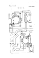
- FIGS. 12 and 13 shows respectively a diagrammatic plan view and side view of a modified form of a machine for checking tickets at the starting point of a journey.
- FIG. 14 shows the chief elements of a frequency-sensitive detector for signals containing one or more frequency com ponents picked up from a ticket by a reading head and fed into the input side of the detector, the output exciting a thyratron or similar power amplifier.
- FIG. 15 shows of storing a ticket derived signal characteristic for the entry point together with a method of deducting from the residual value of the ticket the last travelled fare value, all on the understanding that the signals used are oscillations of different frequencies;
- FIG. 160 shows a ticket with recessed grooves used as channels for magnetic records and it also indicates the purpose and the space reserved on the ticket for different kind of signals, on the understanding that said signals consist of pulses.
- FIG. 1611 shows a side view of such ticket with recessed grooves.
- FIG. 17 gives a fundamental logical diagram for the function of the ticket system at the entry side, to facilitate the explanation of the application of pulse technique to the invention.
- FIG. 18 shows the reading heads and their positions respectively opposite the ticket grooves, in the entry registration unit.
- FIG. 19 shows the connection of said reading heads to checking and entry number recording units in the entry registration apparatus.
- FIG. 20 shows the reading heads used in the Exit Registration Apparatus and respectively their positions opposite the ticket grooves
- FIG. 21 shows the connection of said reading and recording heads with checking the fare value calculating and final ticket value recording units in the Exit Registration Apparatus.
- FIGS. 22 and 23 are schematic diagrams modifying FIGS. 20 and 21 for use in the Entry Registration Apparatus.
- FIG. 24 illustrates a fare device which could be used in a time-lapse and zonal system combination.
- the tickets may be strong plastic tapes combined with such substances as would be receptive to electrical or magnetic field variations, as explained above.
- a passenger may buy a ticket for a definite interzone distance and be able to use it on any route to cover the prescribed number of zone stages. This would lead to a simplification of the ticket systems as known today.
- Passengers may supply themselves in advance with books of preferred zone tickets, and these would be applicable anywhere within the transport system.
- the specialization of a ticket would begin at the moment of entering a bus, railway station or tram, etc. This is, according to the invention, to be achieved by recording on the ticket" a series of pulses the frequency of which would be different or the pulse order of which would be different, for different fare stage zone distances.
- a ticket holder upon entering a vehicle or station platform would place his ticket into a slot from which the ticket is guided into a machine where another series of pulses is magnetically or otherwise imprinted, and immediately afterwards, the ticket is reoffered to the ticket holder.
- This second signal is now to be characteristic for the starting station, or the zone in which the journey was started.
- the passenger leaves the vehicle, he places the ticket into another slot from which the ticket is passed on to a reading head reading the frequency or pulse number of the oscillations present on the ticket.
- Each station within a given traffic route would be allocated a definite pulse combination or pulse frequency.
- a bus driving through different zones of a town would generate in the ticket control machine signals which would alter according to a preset plan, either continuously. or at each point of transit from one zone into another.
- the idea of the invention is further to let the three informing elementsthe zone distance frequency prerecorded on the ticket and symbolizing the ticket value, the zone starting frequency recorded only at the moment the passenger registers his ticket when mounting the vehicle, and the zone exit frequency, generated by the ticket machine at the moment the vehicle halts at a given stop, act together by electronic means, and to show up by visual indicators, or also by mechanical means, whether the prepaid fare was fully paid, underpaid, or overpaid.
- the said oscillations may also be carried by subsonic pulses to render imitation more difficult. Also combination of audiofrequencies may be used to represent a signal.
- FIG. I indicates the signal elements on an individual value token or ticket.
- a magnetic track A along which magnetic pulses may be recorded representing the value of the ticket.
- a separate but closely adjacent checking line C is provided, for example detectable by photoelectric polarized or nonpolarized light sensitive means, and the like.
- zone entry signals are electronically compared with the specific zone pulses of the exit station, and the result of this comparison is then further compared with the signal on the token which defines the price paid for the ticket, i.e., the signal on recording track A.
- the machine will tell the ticket holder whether he has paid the right amount, or too much when the machine would refund the balance, say in the form of another ticket of the described type, or whether he has paid too little for the journey when the machine would demand the balance.
- FIG. 2 indicates the functional buildup of a ticket which has a record of the progressive devaluation of the ticket as a consequence of multiple use.
- such ticket would permit its holder to make many minor purchases with such ticket, up to a prepaid value before the ticket becomes finally exhausted or invalid.
- a passenger holding such ticket may make a number of individual journeys at any intervals of time, up to a total mileage, or up to a total number of travel zones.
- the pulse tracks B--B would register the oscillation or number of pulses allocated to a particular point of passenger entry into the vehicle. This is however not necessarily a record of the value of the ticket if we assume that all tickets have one cumulative value, say equivalent to 30 average journeys, or 50 miles, or fares for zones.
- a ticket would be issued which would have a cumulative value.
- automatic sensing and control circuitry would be responsive to insert this expended usage onto the ticket.
- the time when information indicative of 75 zones of expended travel had been read onto the ticket automatic circuitry would be responsive to determine this occurrence.
- the ticket when the ticket is initially issued, it would contain or have recorded thereon actual information which is equivalent to a specified prepaid number of journeys, or miles, or fares. In this instance, as the ticket is successively used in a transportation system the expended journey, or miles, or fares zones would be subtracted from the balance or residual resulting from the original recordation of information on the ticket.
- the token or ticket may be imprinted or punched with a devaluating mark and then reissued so that it may be used as a receipt.
- the use time of the ticket its holder may be informed by the machine when registering how much of the ticket value is left, say by means of luminous digits, or by issuing a receipt. Still other methods aiming at the production of current information will be described later.
- aggregate value tickets may be allowed in all forms of transport permitting free changeover without regard to the factor time. That is, the person utilizing the ticket would not be limited to any particular interval of time in which he must transfer from transport vehicle to another.
- FIG. 5 shows an Entry registration machine mounted in a vehicle, say a bus
- FIG. 6 shows an Exit registration machine also mounted in the same vehicle.
- Numeral 1 signifies the hull of the checking near the entry door
- 2 is a slot for inserting the ticket
- 3 is a delivery platform on which the ticket is reoffered by the machine.
- the conveyor belts must be so thin that the magnetic induction obtained in the reading heads from the pulse record on the ticket would not be materially attenuated.
- the arrangement may be so that the endless sections of the belt are narrowed and several such are arranged along the whole path with free spacings between them where the magnetic heads may directly touch the passing ticket.
- the ticket finally emerges at the lower slot and platform 3.
- the drawing shows at the upper part of the belt 4 three rectangular figures marked [3,, 01,, [3 These represent three reading heads which are so placed in relation to the feed system of the ticket that they come to face the recording tracks B-A-B, see FIGS. 1 and 2.
- the reading head in the middle is connected to an amplifier and checking unit 16 which checks the control frequency recorded on lines C," see FIG. 2 or 3.
- the set would strike a thyratron whose output would be passed through the solenoid 17 geared to a flaplike extension 19 in the lower face of the ejection platform 20.
- the ticket emerges from the conveyor belts, it will drop into the retaining box 21.
- the unit would cause another thyratron or the like to strike whose output would pass through, for example, an electric door lock attached to the gate mechanism for the passenger, for example such system as illustrated by FIGS. 7 and 8.
- the arrangement may be slightly modified in that the flaplike extension 19, FIG. 5, by means of spring tension would be retained in the ticket reject position (interrupted line), that is, in a position through which the ticket is guided into the retention basket 21 instead of being returned to the ticket holder. Only if the electromagnetical actuator 17 is energized, the extension 19 is withdrawn. The condition for this to happen is, as already explained, that the detector and thyratron stage 16, FIG. 18 is excited by the correct genuity checking signal on the ticket when passing through the entry registration unit.
- the output signal from unit 16, alone or in combination with said selective ticket returning function may be used also for operating electropneumatic doors or arresting latches for entry gates and the like, for example, such as illustrated in FIGS. 7 and 8.
- the presence of the genuity checking frequency on the ticket at the entry point of a journey proves that the passenger had paid for his preceding journey which he made with the same ticket. If he had avoided exit registration, this is discovered in the entry registration machine and according to one alternative of the invention the ticket would be withdrawn and the ticket holder would be prevented from passing through the entry gate of the vehicle.
- the genuity checking signal on the ticket or rather its absence, causes a signal to be recorded on the ticket but the passenger is admitted into the vehicle; the mentioned signal is detected in the exit registration unit there causing a penalty deduction from the ticket value in addition to the normal fare value deduction.
- the heads [3, and [3 have no other purpose than either to check that there is no remnant signal on recording tracks B- B, or alternatively, to apply an erasing signal to these tracks so as to ensure that no such spurious record may be present on them, such as may produce faulty results in the latter phases of the registration cycle.
- the ticket In its further progress the ticket would pass recording heads v B and B and these impress upon tracks BB a specific signal to signify a specific point of entry along the route of the vehicle concerned.
- the zone frequency may be a continuous train of oscillation, or a chain of pulses.
- unit 23 emits a constant number of pulses per second, whenever the vehicle stops within a definite fare zone, but changes when the vehicle passes into a new fare zone.
- the adjustment of the frequency is obtained by means of a switch 24, say near the drivers seat. It would be the duty of the driver to advance the switch by one step each time he is about to enter a new zone.
- the switch arm 24 may be geared to the wheels of the vehicle and may be advanced continuously, in small steps representing subdivisions of zones.
- the block marked (1' does not signify the use of a magnetic head but only the relative position of the middle track and the [3 tracks.
- the magnetic head marked 0: serves to check another genuity signal, namely that optionally recorded alongside tracks B, on track D, FIG. 2.
- the magnetic head 0:" erases the genuity checking signals on track C and/or D respectively.
- An oscillator generating a high-frequency signal in w" is not shown in the diagram.-
- the two outer playback elements [3 and ,3 feed into unit 35 storing there a memory of the pulse number recorded on the ticket on tracks B"-B.”
- the pulse number thereby stored in unit 35 is now compared with the pulse number stored in a unit 36 connected to 23, and the comparison takes place in the unit marked COM-," 37, where these numbers are subtracted, or divided if a geometrical system is used, and stored.
- lts (COM-) contents is then added to the content of 35A, and then passed to the transfer unit 38 which in turn, responsive to an order obtained from the travelling ticket itself, is fed into the head 01,.
- a mechanical function may also be attached to the transfer unit 38 in that it would give free a gate on the condition that the number of aggregate consumed values as signalled from recording line A" on the ticket plus the last travelled fare value is not larger than that paid for.
- From the COM+ unit, 35A may be derived information concerning the number of zones consumed, or how many are still available for use on the ticket.
- Another set of heads, [3 a [3,, is interposed between the group 01 B 3,, and head :1 Their purpose is to erase all signal records on the ticket. The erasing is done in the way known for electroacoustical magnetic recording apparatus,
- the oscillator required for generating the erasing signal is not indicated in FIG. 6.
- the heads (1 B B are not required at all if the system is worked by pulse coding techniques since these usually operate with synchronizing clock pulses so that a new pulse automatically overrides an old one.
- Derived from unit 35A or 38 may be an alarm signal which comes in operation as soon as the chosen value limit is reached and the same may, for example, energize a magnet 40 actuating a diverting flap 42 causing the ticket to drop into the retaining box 41. Simultaneously a receipt may be issued by the machine stating the amount by which the paid ticket value was higher than the actually travelled value. The idea of such arrangement would be to refund the passenger either in case or when the next ticket is bought. Such information may be marked on the ticket by indelible processes, and be controlled from units 35A or 38, with or without digital conversion devices.
- the checking system may consist, for example, of tuned filters with associated amplifiers and relay stages and variable combination of such tuned stages may be combined at will, so as to make the unit responsive to a definite combination of input signals.
- a zero signal would be transmitted to the comparing or checking units I6.
- Checking units 16 would be effective to determine that the ticket has not been expended. This can be considered a positive or specific validity signal which would then be passed to the output acceptor or dispensing unit 211. A positive validity signal in this instance would close the flaplike extension W and allow the ticket to be subsequently dispensed to the user.
- a negative validity signal would be generated by the checking unit 16 which would in turn move the fiaplike extension 19 to prevent the first exit fare device acceptor or dispensing means from selectively dispensing the fare device or ticket to the user.
- the ticket would then proceed along the conveyor system and be carried to the writing or recording transducer heads [3 and [3,.
- the data generator or pulse unit 23 would write or record on the tracks B information indicative of the point of entry.
- the reading or transducing head generally shown as m would be effective to transmit information from any one of the other genuity or validity tracks previously mentioned with reference to FIGS. I through 3.
- These other validity tracks could be utilized for a variety of purposes, such as the prevention of counterfeiting, or, to be more fully explained, for assuring that the user register his ticket when entering the entry machine.
- This signal is also passed to checking unit I6 which will operate to selectively retain or dispense the ticket at the first fare device acceptor means 21, previously discussed.
- the data generator or unit 23 is responsive to simultaneously generate information which is indicative of a point of entry for use at the first fare device receiving means or entry machine shown in FIG. 5, and also effective to selectively pass this information to the fare device receiving means shown in FIG. 6.
- data generator means 23 produces changeable fare information which can be simultaneously utilized to energize the entry receiving machine and the exit receiving machine.
- Transducer or reading heads [3,, and B will read the information originally imparted on tracks B by the writing heads 8; and 8., at the point of entry. Substantially current with this operation, reading or transducer head a is effective to read the aggregate value in track A, in this particular example it being zero.
- the arithmetic unit is shown generally by the continuation of registers, comparators and transfer registers.
- the comparator 37 is responsive to the information imparted on tracks B at the original point of entry and the new fare information produced by data generator 23 which is indicative of exit fare information.
- the comparator 37 will produce an output of IS units.
- This information will then be added in 35A to the amount read by the transducer 0: in this instance or example zero.
- a total arithmetic output signal of 15 is generated by data or comparator plus 35A.
- a total of 15 units will then be imparted or recorded on the A-track of the fare device or magnetic ticket by transducing head 01,.
- This value presently recorded on track A will be same value that will subsequently be read by a similar entry machine transducing head a, when the customer reuses his ticket.
- the output signal from unit 35A can also be used to selectively energize the second fare device acceptor or dispenser 41. in a manner similar to that described with reference to unit 21 in the entry machine.
- the fare device or ticket will be dispensed back to the customer at point 41 until such time as the total value of the ticket has been expended. In this example this would occur when the output of adder or comparator 35A reaches a value of 75 units.
- the fare device or ticket now contains a genuity signal or validity signal and a signal indicative of its reduced value.
- the ticket may be reused again since it contains its validity signal and also contains a usable balance.
- the ticket could originally contain 75 units of new worth, and the expendable units would be subtracted from the original total value.
- the ticket would be retained by the unit 41 when the output of comparator 35A reaches a value of 75 units. Again, it is to be emphasized that the 75 units was merely taken for purposes of illustration.
- the validity signal of genuitys signal generator 39 is used to record or write a validity signal onto the ticket, such validity signal capable of taking various shapes or forms.
- Numerous output devices are responsive to the validity signal from checking unit 16. These output devices could be utilized for a multitude of functions. For example the unit could be used to unlock a gate mechanism which allows the passenger to enter the system. Visual or audible alarms could also be connected to the output signal 16f.
- output signal 351' is connected to a visual fare device printing system (not shown).
- the printing system would give a running account of the units remaining on the ticket, in this manner, the customer would not have to rely entirely on the nonvisual magnetic information, indicative of the remaining fare available, not FIG. 11.
- the transducer or erasing head 3, are utilized to erase the information previously used by the arithmetic unit to compute a total balance. After the total balance or fare value or units remaining are calculated this information is erased to prepare the ticket for subsequent use and for the final writing operation of transducer writing head 01,.
- transducer heads [3' and [3" are merely representative of the fact that other operations could be incorporated into the system. The only limiting factor would be the number of tracks which are contained on the fare or ticket device.
- FIG. I4 shows a reading head 82 feeding into an amplifier 83.
- FIG. 14 shows furthermore five band-pass filters 84', 84, 84 84 and 84 the primary or input windings of which are series-connected to the output of amplifier 83. Only band-pass filter 84 is shown in full detail. The number of filters needed depends of the number of different frequencies in the genuity checking signal. Each filter is connected to a relay stage essentially consisting of some kind of detector and DC amplifier 85 a, b, and a final thyratron stage 86 feeding into a load 87.
- FIG. 14 The circuit, FIG. 14 is not new. In all essential parts it was published in the periodical, Elektronische Rundschau", No. 5, 1956, under the title Einselektiver Verstarker mit I Hertz Bandbreite", by W. Nonnenmacher.
- the reading head 82a is another head similar to the reading head 82 in FIG. 14.
- the amplifier block 83a in FIG. 15 in another amplifier of like design to the amplifier 83 in FIG. 14.
- reading head 82a should be considered identical .with the reading head 5,, in FIG. 6 and its duplicate fi,,, FIG. 6 illustrates the principle of the exit registration unit.
- the amplifier 83a and the electrical filters 9I' through 91 together with the relays 92, 93, 94 and so on, represent the signalling store 35 in FIG. 6,
- the said relays are self-holding and once energized by a signal then retain the selected associated circuit.
- the handle 98 is identical with the handle 24, FIG. 5, which in a preceding portion of the disclosure was described to be operated by the driver of a vehicle who sets it to different positions which correspond to fare stage positions of the vehicle within its route.
- the multicontactors on the relays 92, 93, a.s.o. and the connections between them and the contactors on the multithrow switch 97-97 correspond to the block diagram 37 in FIG. 6, as previously explained.
- this comparison is performed by the simple means of combining contactors of the relays which provide the information concerning the zonal position of the vehicle at the entry point, with contactors of the multithrow switch which at any moment represent the zone in which the vehicle happens to be.
- the combination of said two contact groups produces in each instance a definite value step, the zonal value of the distance travelled. For this reason, the function which was previously described to be associated with circuit element block 37, is now according to FIG. 15 performed by the multithrow switch 97 with its combination contactors ll, 12, I3, 14 and so on.
- the reading head 99 corresponds to the reading head at; in FIG. 6.
- Block 102 is an amplifier of similar design as indicated in FIG. 14 and block 103 with time-delay sections A, B, C H is again a series-connected multiple band-pass filter as described for FIG. 14.
- Block I05 contains the relays associated with the output stages of the filters. These relays are again self-holding and therefore play the part of storing the effect of the input signals coming from reading head 99. This role coincides with the function ascribed to block 34, FIG. 6 in accordance with the original specification.
- FIG. 15 the block corresponds to block 35A in FIG. 6. It is here that a comparison between the residual ticket value and the fare value of the journey at the moment of alighting is compared. In the instance of FIG. 15 this is achieved by a network of diode lines, but without detriment to the principle also other comparators such as coordinate selector relays or ferrite networks may be used. The principle would remain in agreement with FIG. 6.
- the block diagram 108 corresponds to the transfer unit 38 in FIG. 6 and in which according to the example the new ticket value (expressed as a debit total consumed fares, or also as a credit remaining residual fare value) is translated into a suitable combination of two out of eight recording frequencies.
- the driving stage for these oscillations is symbolized by block 108 and 109, FIG. 15.
- the recording head 100 corresponds to the recording head a, in FIG. 6.
- the oscillator 113 corresponds to the genuity checking signal generator 39 in FIG. 6. Any of the oscillator circuits for the generation of electrical wave trains, as have become known in the literature of electrical engineering, may be used for latter 1 13.
- the recording head 101 corresponds to the recording head Q in FIG. 6.
- FIG. 15 no erasing heads are shown such as would correspond to the heads 01 B B
- the gating arrangement 111, 112, and 114 corresponds to the indication of the auxiliary order line 38-i in FIG. 6 hereinafter described.
- the reading head 82 faces the genuity checking signal on the ticket when the same passes through the entry registration unit. After amplification in unit 83, the signal passes through one or more band-pass filters, the number of them depending on the number of frequencies contaiped in the checking signal. The buildup of a filter is illustrated only for the second one of the series.
- Each filter unit feeds into the high input impedance of a cathode follower circuit having a double triode 85a85b, and a thyratron or output tube 86.
- the cathode follower amplifier supplies a part of the signal energy across the cathode resistance back into the band-pass filter at the midpoint of the tuning condensers 2C2C, and by means of the variable potentiometer 88 the Q-factor of the filter may thus be set to a desired value.
- Positive feedback can be driven far because of the stabilizing effect of the cathode follower as generally known.
- the output is applied to the grid of 85b via a coupling condenser and a diode 90.
- the signal causes the grid to go negative, the plate current stops which causes the grid of the thyratron 86 to receive a large positive voltage so that the tube becomes conductive.
- a bias voltage opposing smaller values of the signal may be applied to the diode or crystal 90 from the potentiometer 89, thereby further improving the selectivity of the arrangement.
- 87 are the windings of a relay or of an elec tromagnet actuating the ticket gate 19, FIG. 5. The latter is normally spring-loaded and would cause a ticket arriving at 3 to be diverted into the receptacle 21.
- the ticket gate or flap 19 is drawn into the retracted (shown) position and the ticket will be reoffered to the passenger on the tray or platform 10.
- the same output impulse may be used for releasing the latch of an electric door lock or for actuating an hydraulic cylinder for opening the entry door of a vehicle.
- the circuitry of the ticket registration machines contain varying features through the general operation principles may be the same.
- FIG. 15 a detail survey is given of an exit registration machine where the criterion of a signal is its frequency content.
- the reading head 88a faces that track of a ticket passing through the exit machine which is supposed to contain a record of the code frequency for the entry zone or entry station. Therefore the head 82a is identical with head 3,, (or its duplicate B, in FIG. 6.
- the block 83a signifies an amplifier for 82.
- the blocks marked 1, 2, are band-pass filters, for example of the type shown in FIG. 14 and detailed inside the block 84", whereas the blocks 91 each contain a cathode follower amplified as shown in FIG. 14.
- the output relay 87 in FIG. 14 recurs in FIG. as relays 92, 93, 94, 95 and 96 each having multiple banks of contacts. Each of these are connected to contacts of a multithrow switch 97 with operating handle 98 which is identical with the selector switch 24 near the drivers seat, in FIG. 5.
- the five selective relay stages respond to five different signals symbolizing five different zone stages within a given traffic route.
- Any combination of a zone position of the entry station with the zone position of the exit station can be derived from the contacts 11, l2, l3, 14, 15 of the multiswitch, as these signify the zone distances which can he travelled on the considered traffic route.
- Resonance circuit 1 responds, relay 92 and its uppermost contact pair become operative since also the multithrow switch 97 is set to position 1. Plus voltage is put on contact 1 1. This means the passenger has to pay the basic fare for any journey between stops within a zone.
- Block 102 signifies a compression amplifier such as used in amplifiers for loudspeakers in public address systems. which produce an undistorted voice output at fairly even pitch in spite of widely varying input energies at the microphone.
- the tuned filters A -H each are connected to a cathode follower amplifier which, via rectifiers 104, are fed into a translator 105 which resolves the combinations into individual lines.
- the translator may be a diode matrix network (see Engineering Electronics", page 320, John Ryder).
- Another such diode matrix network is block I15 in which both said individual output lines and the output lines from the multiswitch 97 meet. The combination points between them signify the complete register of possible combinations of residual ticket values with last-travelled zone distances and therefore also represent the complete register of all possible new residual ticket values. Individual cable connections to the diode bus lines are taken out in the leads contained in cable 107.
- the leads of I07 are connected to combinations of eight output lines each feeding an oscillator driving stage (the eight driving stages symbolized by block 108).
- the oscillators may be of the transistor type such as published in Engineering Electronics," page 340, or in the chapter, common Schwingshalet Institute, Transistor Kir, by Heinz Richter,
- Block 112 is a gating circuit for the recording of the genuity checking frequency which is allowed to pass the gate and to reach the recording head 101, since a part of the output from the driving oscillator I09 is passed via a rectifier 111 to the grid of the gate tube I14 which thereby is charged positive. However, if there is no output from an oscillator I09, the grid remains in the negative range and tube I14 is nonconductive.
- a few selective reject filters may be placed which may be interposed at choice by means of a switch. so that the value levels above zero at which the ticket shall be invalidated may be fixed.
- the idea for this arrangement would be that passengers though prevented from using the ticket until complete value exhaustion, may obtain refund for the nonused part of the ticket when renewing a ticket at a ticket purchase counter, post office, tobacco shop, or other licensed ticket selling place.
- the unit 115 in FIG. corresponds to the unit 35A in FIG. 6 as far as its function is concerned. It has, therefore, to be shown that also the auxiliary operations which have been claimed to be perforrnable or controllable by unit 35A or unit 38 respectively, FIG. 6, may be controlled by said unit 115.
- the individual output lines 107 coming from the diode matrix network carry when selected a DC voltage and it is obvious that this makes it rather easy to utilize such signal to the lighting of lamps marking the residual value or for the printing of receipt papers.
- the simplest form of a permanent receipt would consist of a strip of paper with 27 squares (if applied to the example FIG. 15) numbered l-27. The strip would pass through a punching machine having 27 hole punching rods facing the named squares on the ticket. The prolonged parts of each rod constitute the plunger of a small solenoid with its coils connected to the said 27 different output lines 107. Any of these leads when singled out by the diode matrix network 115 would energize one of the 27 solenoids and thus punch a hole in the corresponding value square of the receipt.
- the same principle may be applied in conjunction with the switch output lines 11, 12, hereby so that the receipt may also contain a record of the fare paid for the last journey.
- the ticket holder would drop his ticket into the entry registration machine as many times as there are members to the party. Again, when the party alights, he would insert his ticket into the slot of the exit machine as many times.
- the'ticket machines as already described should contain a multiplier element responsive to signals from a separate recording track on the ticket.
- a multiplier track On this multiplier track "a first pulse element would be recorded after the first entry registration of the ticket, the second pulse after the second registration of the same ticket, in short, as many pulses would appear on the multiplier track of the ticket as passengers should be registered for entry into the vehicle.
- the ticket structure in terms of recording tracks having functions, is exemplified in F IG. 3. it resembles the structure illustrated in FIG. 2, namely, tracks 8-8 which receive recordings of the signal marking a definite entry point on the traffic route concerned.
- Track D-D contains either a genuity testing signal, or a signal signifying a limitation of use, such as validity for a limited period of time, hours of the day or the night, or validity within only one part of a city, and so on. it may also combine both functions, that of use limitation definition, and that of genuity definition in general.
- Track CC is again a genuity and protection track mainly for protecting against interference by the track "A" on which a record is made of the cumulative value consumption.
- EE are the signal tracks which as just explained for the contain the information as to how many times a travelled distance should be multiplied in the exit registration machine so as to produce a record on the ticket of the true total consumed fare value.
- FIG. 4 shows a block diagram indicating the function of that part of the entry registration unit which cooperates with the multiplier track" EE which contains the record, for example, of pulses the number of which are proportional to the number of passengers to be covered by the ticket.
- e is the playback head for the tracks "E”
- w is an erasing head
- tr is a trigger
- e" is a recording head.
- the ticket holder when leaving the vehicle, will have to register his ticket again as many times as there are members to his party, including himself. After each registration the multiplier points on track E are diminished by one.
- the arrangement should be so that the rerecording of the said genuity testing signal upon the ticket which according to the general scheme had' been erased after the entry registration, also called checking frequency, should be postponed until the last multiplier pulse has disappeared from the ticket.
- the circuit technique for unfolding such performance need not be exemplified here in detail, but it is obviously easy to employia signal such as derived from a pulse on tracks E" to produce in an amplifier a masking effect, or to produce a suppressor bias on one or more of the values of the amplifier unit amplifying the genuity testing signal to produce a recordon the ticket.
- the said bias would have delayed recovery after the passing of the multiplier pulse read into an associated electronic circuit, thereby obtaining the required prevention of the genuity signal or the like from being recorded on the ticket.
- the amplified incoming genuity checking signal and the internally generated train of pulses would be electronically confronted with each other.
- Each pulse would meet a corresponding pulse, each interval would meet a corresponding interval; if the pulse sequence configuration played back from the ticket, and that generated in the checking unit is the same, a state of balance may be achieved in relation to a third electric or electronic element, say akin to an electric bridge, so that no output signal is obtained from a given section of the circuit.
- the mentioned part of the circuit would produce an output signal, in correspondence to the demand that a ticket should be marked invalid or be retained by the machine, and admission into the vehicle should be refused.
- Some such validity checking system may be used also for purchase tokens in general.
- FIGS. 16a and 16b show the shape of a ticket with its recording tracks placed at the bottom of grooves B,, A, and B Track B, contains clock pulses for synchronizing reading and recording operations on tracks A and B Track A consists of two half record sections, the left half reserved for memorizing a signal applied to the ticket at the entry station, henceforth called entry-station number or zone number, and the right half reserved for recording on the ticket the vehicle check number or vehicle route checking number.
- Track B contains the aggregate still unused, value number of the ticket, also expressed in binary coded form. What had been called the genuity checking signal is to be recorded on track A when the ticket passes through the exit registration machine, by filling up the whole of this track with a continuous train of clock pulses.
- Block 115 means IN- SERT TICKET.
- Block 116 means a testing operation: WAS LAST JOURNEY PAID? The YES answer goes to block 117 symbolizing the stage when TOUR-CHECKING and STA- TION NUMBERS are recorded on ticket.
- FIG. 18 shows how a ticket in the entry machine passes the various reading and writing heads.
- BI/a, Bl/b, a/a are reading heads
- a/b is a recording head.
- the ticket passes Bl/a from which comes the clock pulses recorded on the ticket. From a/a come also clock signals (if the ticket is valid) or station numbers and tour checking numbers (if the ticket is invalid, or respectively releases a penalty charge operation).
- FIG. 19 gives a block diagram of the circuit used.
- Each head is associated with an amplifier 123, 127, 132 and respectively; 123 and 127 feed into a pulse shaper circuits 124 and 128 such as described in A digital Electronic Correlator, page 9, by Henry E. Singleton (Research Laboratories of Electronics Massachusetts Institute of Technology).
- a stroboscopy 125 diminishes the width of the square wave to avoid overlap phenomena in the AND circuit 126 which is a coincidence circuit checking that for every clock pulse coming from 31/11 is there also one coming from a/a.
- a pulse width control circuit is shown on page 296, Engineering Electronics," John D. Ryder.
- a half-adder, block 129 compares the pulse signals coming from ticket track I, and 2 and if any of the pulses are missing on track 2, the bistable flip-flop F, would change over and hold until the next zero reset impulse (NP) comes. Thereafter the ticket passes a contactor OP. By closing OP either the flip-flop F or F is set, depending on whether F, was set or not. This means, either the door opening impulse line 131 is energized if F: is set,-or the penalty request is put to the passenger via information line 130, or the automatic penalty process comes into operation, if F is set.
- a number recording register is set to the number code which corresponds to the station number just applicable and to the route checking number just applicable.
- a switch for adjusting these numbers is not shown in FIG. 19 but is essentially identical with the switches 24 in FIG. 5 and 97, 98 in FIG. 15. These switches may be mounted upon a control board next to the driver's seat, so that the zone numbers may be readily adjusted all transit points from one fare stage to another.
- the tour checking numbers are adjusted only once for every tour, namely, at the terminal stations of the route.
- FIG. 20 is shown how the ticket plate passes the various magnetic heads in the exit registration machine.
- 116 is again the ticket, the same as described in FIG. 160, 12.
- This contactor may of course be also a photoelectric switch. It resets to zero all flip-flop stages (F, F at the same time causing the code positions as preset by means of the switch (24 in FIG. 5) for the now applicable station number. and the tour checking number, to be applied to the shifting re gister I24.
- the ticket passes the pair of heads Bl/a. a/a.
- the flip-flop F coresponsive to the actuating of the contactor 0P sets to the alternative position with output line 120 and prohibits further operation with the ticket.
- ticket invalid On the information panel a notice would appear, ticket invalid. While the contents of the upper part of the shift register become zero as a rule, the lower part contains the difference between the entry and exit station numbers, that is, the value which must be deducted from the credit amount still left on the ticket.
- a selector switch DC may alternatively connect to some of the counting positions of the shift register 124.
- a ticket operated contactor DP positioned prior to contactor OP, applies voltage of such sign to the switch DC and respectively to the selected position of the shift register, that any count of the number of travelled zones reaching that position would be deleted.
- Two or more of such switches DC may be provided, each capable of deleting a different number of count pulses on application of the deleting voltage via DP.
- the next operation is the deduction of the travelled zone value from the ticket value. This subtraction is done when the ticket passes the heads Bl/b and B2/b.
- the head 31/! feeds clock pulses into the terminal 118 of the shift register, in such a way that one bit after the other goes to the subtractor unit 122, together with the signal played back from the reading head BZ/b representing the still unused value of fare stages on the ticket.
- the subtraction result is fed back into the shift register even this time, and stored there for a short period of time. If now the fare stage credit number on the ticket prior to the subtracting operation had been smaller than the number of fare stages just travellede.g., if the subtraction result is negative;-this can be detected by the sign of the numeral or digit.
- the ticket is valid, the remnant value of the ticket is recorded on trackB by means of the recording head 82/0, the information coming from the shift register via the AND circuit with its 0P switch. Also, the tour checking and the station numbers on track A of the ticket are now eliminated by being changed into clock pulses with the aid of the recording head a/c. For this operation, the clock pulses come from head 51/0.
- the code system is of such a nature that it is unnecessary to use erasing operations in order to delete information from a track.
- One of the possibilities offered by the invention is a flexible adaptability to fare fixing policies. Sometimes it is desirable to offer passengers a discount on fares for longer travel distances, perhaps to encourage them to live further away from a town center. It is now within the scope of the proposed electronic zone accounting system to reduce fares for long trips, as compared with short ones. It would be done by loos ing zone representing pulses, say, one in every five, from a certain minimum travelled zone number onwards, as stored in the element COM-" unit 37, FIG. 6. Generally, speaking. the electronic calculation of the fare paid may be so arranged that a certain discount is automatically granted if the values exceed one or more prearranged levels.
- switches may be provided by means of which certain counting elements would be short-circuited or earthed when they are reached in the course of the internal counting process, or, a condenser capacity may be increased so that a larger charge is required to produce a glow discharge thus causing two or three pulses to be counted as one.
- Other examples may be given when magnetic cores are used as memory elements.
- tokens or tickets which are plates having shaped cross sections.
- An example of such a token is shown in FIG. 9 and the longitudinal cross section H0. 10.
- the active recording tracks are placed into the recessed grooves 767676.
- the material of this token may be brass electroplated with a magnetically coercive substance, or it may be made of a plastic compound.
- the active layer may cover only the grooves if desired.
Abstract
A token having electrically operable storage means is accepted and stored data is read from the token, data compared, and passenger fare computed.
Description
United States Patent John Woligang l-lalpern 2 Field Court, London, W.C.1, England 827,095
May 13, 1969 Sept. 28, 1971 Continuation of application Ser. No. 629,046, Feb. 10, 1967, now abandoned which is a continuation-in-part of application Ser. No. 261,529, Feb. 27, 1963, now abandoned and a continuationin-part of 659,196, Feb. 16, 1967, now abandoned.
[72] Inventor App]. No. Filed Patented [54] AUTOMATIC FARE CHARGING DEVICE 21 Claims, 25 Drawing Figs.
521 U.s. c1 235/6117'1'1, 235/61.8 A [51] lnt.C1 ..G06k2l/00 [50] Field of Search 235/99, 61.114, 6| .6. 6117; 194/4; 340/51 [56] References Cited UNITED STATES PATENTS 2,906,505 9/1959 Orr et a1. .1 235/99 X 2,907,521 10/1959 Cunningham 235/99 Primary Examiner- Daryl W. Cook ABSTRACT: A token having electrically operable storage means is accepted and stored data is read from the token, data compared, and passenger fare computed.
PATEHTEDSEP28I97 SHEET 01mm 3009,1300
' A {A B A a so cc DB aoc c o s 53 age k? 5551535 z;
PATEiJTEUSEPmIaY: 3 609 300 SHEET 02 0F 10 PATENTED SEP28 19.
SHEET 03 [1F 10 PATEHHZU swam/1 3609 300 sum 'nu 0F 10 FIG. 13
000mm SEP28 :97: 3,609,300
AUTOMATIC FARE CHARGING DEVICE This application is a continuation of application Ser. No. 629,046,- filed Feb. 10, 1967, which in turn was a continuation-in-part of application Ser. No. 261,529, filed Feb. 27, I963 and Ser. No. 659,196, filed Feb. 16, 1967, these applications now being abandoned.
This invention relates to record controlled data handling and computer devices and particularly to methods and means for calculating and recording fares in public transit systems.
The need for devising improved methods for charging passengers has been recognized by experts and laymen alike as a part of making commuter services in towns and cities more attractive. It is becoming more and more desirable to find such improvements. Traffic congestion in many places reduces speed to such an extent that both public and private vehicles users are severely hampered.
The main object of the present invention is to provide a record controlled data handling system on vehicles or at stations by means of which it should become possible drastically to reduce all money handling operations on vehicles or at stations.
Another object of the invention is to provide means on vehicles or at stations for generating the data which in cooperation with a record bearer will compute fares in accordance with some equitable principle, and use the computed fare value for making a new record on a record bearer.
A subsidiary object of the invention is to provide commuteroperated equipment by which a passenger can without the attendance of a conductor ascertain the fare chargeable or have it automatically charged at the end of a journey.
An important object of the invention is to specify a method for making it recognizable on a record bearer if a passenger has failed to procure a record of the fare payable, and thus to make physical constraints (turnstiles etc.) unnecessary.
A subsidiary object of the invention is also to procure means by which a passenger who has failed to procure a record of the fare payable at an exit point should be charged a penalty when he next uses a public transport vehicle.
These and other objects will become apparent by the subsequent description. Many of the circuits however are also conceived to be usable with advantage in other types of cnsumption or service places.
The present invention comprises apparatus for introducing a record bearer into a record sensing system, apparatus for storing the sensed information and for comparing it with information derived from a data generator, other data generators for producing data significant for the points of entry and exit respectively, means for changing said significant data and means for recording computer output data on a record bearer.
Broadly the invention provides record controlled input and output systems for data relevant to consumption estimation in public servicing places, and more particularly for fare estimation in passenger transit systems in which the record bearer include magnetic material for recording on it initial data significant of any prepaid aggregate fare value, and having first record checking means operative at a point of passenger entry, for recording on a record bearer data significant of the point of entry, and second record bearer checking means operative at a passenger's destination for comparing said firstmentioned information and said second-mentioned information with information produced by said second checking means significant of a point of passenger exit from a vehicle or from a station, and for recording on said record bearer data indicative of the prepaid value minus all fares including the last one.
One feature of the invention is that the said record bearer is intended to be used by passengers in a manner similar to a prepaid season ticket, however with the difference that unlike a season ticket its use is limited not by a fixed period of validity but by a ceiling of aggregate travelled fare units, or in some cases also a ceiling of aggregate travel time units.
Another feature of the present invention also relates to the use of several recording tracks having different functions, and of the use of data which are characterized by the number of oscillations per time unit, or by a combination of such oscillations.
Another feature of the invention is the use of several recording tracks having different functions, and the use of data characterized by the number of pulse bits or pulse configurations recorded or recordable on a record bearer.
Still another feature of the invention is the provision of a computer controlled means for admitting at any one time only a predeterminable maximum number of passengers into the vehicle for entry registration of record bearers.
Still another feature relates to methods of guarding against misuse of the system by providing circuits which at an entry point apply to a record bearer a signal devised to identify a particular vehicle or a particular route, and further by provid ing at exit points of said vehicles circuits which compare the identity of the recorded vehicle signal with the said vehicle signal.
One of the features of the invention is a circuit by means of which a group of passengers collectively travelling a certain number of fare stages may be charged against the record of a single record bearer.
Still another feature of the invention are circuit means by which traffic authorities may flexibly apply discounts to different travelled fare stage distances to encourage travel during certain hours of the day or on certain days of a week, etc.
The invention will now-be described by way of an example in which the invention is applied to a transport system and in which the record bearer is a ticket or token. This example is described with reference to the accompanying drawings in which:
FIG. 1 illustrates diagrammatically the record tracks on a ticket or token having different functions, and which functions are to be provided for single journeys only.
FIG. 2 illustrates the record tracks having different functions, and to be provided when each individual ticket or token entitles to a multiplicity of journeys up to a predetermined and prepaid maximum of aggregate fare stage distances.
FIG. 3 shows a similar track pattern with additional tracks to be provided when several persons use a single ticket or token as a joint ticket (group ticket).
FIG. 4 is a block diagram of a circuit capable of recording on a ticket or token instruction references concerning the number of times a travelled fare charge at an exit point must be multiplied with in order to enable a group of persons to record their joint fare charge on a ticket or token.
FIG. 5 shows a diagrammatic scheme of a machine and associated devices for checking tickets at the starting point of a journey.
FIG. 6 shows a diagrammatic scheme of a machine and associated devices for checking tickets at the finishing point of a journey.
FIG. 7 shows in part an exit and entry door of a road vehicle equipped with the electrical and mechanical facilities of the system of this invention.
FIG. 8 is a top plan view of FIG. 7.
FIG. 9 is a perspective view of an exemplary form of ticket for use with the system of the invention.
I FIG. 10 is a longitudinal section of the ticket of FIG. 9.
FIG. 11 shows in plan view part of the ticket of FIG. 9 with numerals imprinted or engraved on it which are progressively deleted or over printed as the initial value of the ticket decreases.
FIGS. 12 and 13 shows respectively a diagrammatic plan view and side view of a modified form of a machine for checking tickets at the starting point of a journey.
FIG. 14 shows the chief elements of a frequency-sensitive detector for signals containing one or more frequency com ponents picked up from a ticket by a reading head and fed into the input side of the detector, the output exciting a thyratron or similar power amplifier.
FIG. 15 shows of storing a ticket derived signal characteristic for the entry point together with a method of deducting from the residual value of the ticket the last travelled fare value, all on the understanding that the signals used are oscillations of different frequencies;
FIG. 160 shows a ticket with recessed grooves used as channels for magnetic records and it also indicates the purpose and the space reserved on the ticket for different kind of signals, on the understanding that said signals consist of pulses.
FIG. 1611 shows a side view of such ticket with recessed grooves.
FIG. 17 gives a fundamental logical diagram for the function of the ticket system at the entry side, to facilitate the explanation of the application of pulse technique to the invention.
FIG. 18 shows the reading heads and their positions respectively opposite the ticket grooves, in the entry registration unit.
FIG. 19 shows the connection of said reading heads to checking and entry number recording units in the entry registration apparatus.
FIG. 20 shows the reading heads used in the Exit Registration Apparatus and respectively their positions opposite the ticket grooves, and
FIG. 21 shows the connection of said reading and recording heads with checking the fare value calculating and final ticket value recording units in the Exit Registration Apparatus.
FIGS. 22 and 23 are schematic diagrams modifying FIGS. 20 and 21 for use in the Entry Registration Apparatus.
FIG. 24 illustrates a fare device which could be used in a time-lapse and zonal system combination.
By way of introduction it may be assumed that in the embodiment to be described the tickets may be strong plastic tapes combined with such substances as would be receptive to electrical or magnetic field variations, as explained above.
It should be assumed that there are differential fares for different distances, and that for practical purposes a route is subdivided into a number of fare stages, or zones. In a town where there are many routes, all routes would be subdivided into fare stages of, as far as possible, equal zone distances.
By means of the system to be proposed, a passenger may buy a ticket for a definite interzone distance and be able to use it on any route to cover the prescribed number of zone stages. This would lead to a simplification of the ticket systems as known today.
Passengers may supply themselves in advance with books of preferred zone tickets, and these would be applicable anywhere within the transport system. The specialization of a ticket would begin at the moment of entering a bus, railway station or tram, etc. This is, according to the invention, to be achieved by recording on the ticket" a series of pulses the frequency of which would be different or the pulse order of which would be different, for different fare stage zone distances.
In practice the system would work as follows: A ticket holder, upon entering a vehicle or station platform would place his ticket into a slot from which the ticket is guided into a machine where another series of pulses is magnetically or otherwise imprinted, and immediately afterwards, the ticket is reoffered to the ticket holder. This second signal is now to be characteristic for the starting station, or the zone in which the journey was started. When finally the passenger leaves the vehicle, he places the ticket into another slot from which the ticket is passed on to a reading head reading the frequency or pulse number of the oscillations present on the ticket.
Each station within a given traffic route would be allocated a definite pulse combination or pulse frequency. A bus driving through different zones of a town would generate in the ticket control machine signals which would alter according to a preset plan, either continuously. or at each point of transit from one zone into another.
The idea of the invention is further to let the three informing elementsthe zone distance frequency prerecorded on the ticket and symbolizing the ticket value, the zone starting frequency recorded only at the moment the passenger registers his ticket when mounting the vehicle, and the zone exit frequency, generated by the ticket machine at the moment the vehicle halts at a given stop, act together by electronic means, and to show up by visual indicators, or also by mechanical means, whether the prepaid fare was fully paid, underpaid, or overpaid. The said oscillations may also be carried by subsonic pulses to render imitation more difficult. Also combination of audiofrequencies may be used to represent a signal. FIG. I indicates the signal elements on an individual value token or ticket. In the center, there is a magnetic track A along which magnetic pulses may be recorded representing the value of the ticket. To anticipate the possibility of this signment being forged, a separate but closely adjacent checking line C is provided, for example detectable by photoelectric polarized or nonpolarized light sensitive means, and the like.
There are also lines or recording tracks 8" on each side of the ticket which in the case of transport vehicles operating on zone-divided routes would mark the particular point of entry within the route.
When the passenger leaves the vehicle he must insert his ticket into another checking machine, say in the vicinity of the drivers seat, or at station turnstiles. In this machine the zone entry signals are electronically compared with the specific zone pulses of the exit station, and the result of this comparison is then further compared with the signal on the token which defines the price paid for the ticket, i.e., the signal on recording track A.
As a result of these comparisons, the machine will tell the ticket holder whether he has paid the right amount, or too much when the machine would refund the balance, say in the form of another ticket of the described type, or whether he has paid too little for the journey when the machine would demand the balance.
FIG. 2 indicates the functional buildup of a ticket which has a record of the progressive devaluation of the ticket as a consequence of multiple use. According to a form of the invention, such ticket would permit its holder to make many minor purchases with such ticket, up to a prepaid value before the ticket becomes finally exhausted or invalid. Applied to the transport field, a passenger holding such ticket may make a number of individual journeys at any intervals of time, up to a total mileage, or up to a total number of travel zones.
As before, the pulse tracks B--B would register the oscillation or number of pulses allocated to a particular point of passenger entry into the vehicle. This is however not necessarily a record of the value of the ticket if we assume that all tickets have one cumulative value, say equivalent to 30 average journeys, or 50 miles, or fares for zones.
Thus, it can be seen that a ticket would be issued which would have a cumulative value. In other words, as the ticket is progressively used in the transportation system, automatic sensing and control circuitry would be responsive to insert this expended usage onto the ticket. Thus, the time when information indicative of 75 zones of expended travel had been read onto the ticket, automatic circuitry would be responsive to determine this occurrence. On the other hand, when the ticket is initially issued, it would contain or have recorded thereon actual information which is equivalent to a specified prepaid number of journeys, or miles, or fares. In this instance, as the ticket is successively used in a transportation system the expended journey, or miles, or fares zones would be subtracted from the balance or residual resulting from the original recordation of information on the ticket.
Such ticket, therefore, would not be withdrawn by the machine after every use, but it would be reoffered to the ticket holder. Only when the sum of the consumed values reaches or approaches the actually paid-for value of the token or ticket. the same would be automatically retained by the checking machine. As will be seen from an alternative version explained later on, the token or ticket may be imprinted or punched with a devaluating mark and then reissued so that it may be used as a receipt. During the use time of the ticket its holder may be informed by the machine when registering how much of the ticket value is left, say by means of luminous digits, or by issuing a receipt. Still other methods aiming at the production of current information will be described later. In larger towns aggregate value tickets may be allowed in all forms of transport permitting free changeover without regard to the factor time. That is, the person utilizing the ticket would not be limited to any particular interval of time in which he must transfer from transport vehicle to another.
A description follows of entry and exit checking machines for aggregate value tickets according to one form of the invention. A similar description for the first-mentioned singlevalue" tickets need not be given since such checking machine would contain one or more features of the devices described hereunder.
FIG. 5 shows an Entry registration machine mounted in a vehicle, say a bus, whereas FIG. 6 shows an Exit registration machine also mounted in the same vehicle.
To avoid the use of two thyratrons, the arrangement may be slightly modified in that the flaplike extension 19, FIG. 5, by means of spring tension would be retained in the ticket reject position (interrupted line), that is, in a position through which the ticket is guided into the retention basket 21 instead of being returned to the ticket holder. Only if the electromagnetical actuator 17 is energized, the extension 19 is withdrawn. The condition for this to happen is, as already explained, that the detector and thyratron stage 16, FIG. 18 is excited by the correct genuity checking signal on the ticket when passing through the entry registration unit. The output signal from unit 16, alone or in combination with said selective ticket returning function, may be used also for operating electropneumatic doors or arresting latches for entry gates and the like, for example, such as illustrated in FIGS. 7 and 8.
As will be seen from the description of the ticket system later on, the presence of the genuity checking frequency on the ticket at the entry point of a journey proves that the passenger had paid for his preceding journey which he made with the same ticket. If he had avoided exit registration, this is discovered in the entry registration machine and according to one alternative of the invention the ticket would be withdrawn and the ticket holder would be prevented from passing through the entry gate of the vehicle. According to another alternative, the genuity checking signal on the ticket, or rather its absence, causes a signal to be recorded on the ticket but the passenger is admitted into the vehicle; the mentioned signal is detected in the exit registration unit there causing a penalty deduction from the ticket value in addition to the normal fare value deduction.
The heads [3, and [3 have no other purpose than either to check that there is no remnant signal on recording tracks B- B, or alternatively, to apply an erasing signal to these tracks so as to ensure that no such spurious record may be present on them, such as may produce faulty results in the latter phases of the registration cycle.
In its further progress the ticket would pass recording heads v B and B and these impress upon tracks BB a specific signal to signify a specific point of entry along the route of the vehicle concerned. According to the nature of the signal one may for example speak of a ZONE FREQUENCY" or a ZONE PULSE NUMBER, either of which may be thought of as being generated in a unit 23, FIG. 5. The zone frequency may be a continuous train of oscillation, or a chain of pulses. According to one proposal, unit 23 emits a constant number of pulses per second, whenever the vehicle stops within a definite fare zone, but changes when the vehicle passes into a new fare zone. The adjustment of the frequency is obtained by means of a switch 24, say near the drivers seat. It would be the duty of the driver to advance the switch by one step each time he is about to enter a new zone.
Alternatively, the switch arm 24 may be geared to the wheels of the vehicle and may be advanced continuously, in small steps representing subdivisions of zones.
After this phase, there are now recorded on the ticket the signal signifying a particular point of entry. The whole procedure of recording this signal on the ticket may be so fast that it would constitute no holdup for the passenger.
The block marked (1' does not signify the use of a magnetic head but only the relative position of the middle track and the [3 tracks. The magnetic head marked 0: serves to check another genuity signal, namely that optionally recorded alongside tracks B, on track D, FIG. 2. The magnetic head 0:" erases the genuity checking signals on track C and/or D respectively. An oscillator generating a high-frequency signal in w" is not shown in the diagram.-
We assume now that the passenger has made his journey and wishes to alight. All he has to do is to drop the ticket into the slot near the exit door, see FIG. 6. The ticket after being seized by the belts guided by the pulleys 25-28, and 29-33, first passes heads (1 B B The middle element a, feeds into unit 34, a storing unit, where the aggregate number of zone pulses as are recorded on line A," FIG. 2 (if any) are stored and passed on to an arithmetic comparator or adding unit 35A also serving as a store unit. The two outer playback elements [3 and ,3 feed into unit 35 storing there a memory of the pulse number recorded on the ticket on tracks B"-B." The pulse number thereby stored in unit 35 is now compared with the pulse number stored in a unit 36 connected to 23, and the comparison takes place in the unit marked COM-," 37, where these numbers are subtracted, or divided if a geometrical system is used, and stored. lts (COM-) contents is then added to the content of 35A, and then passed to the transfer unit 38 which in turn, responsive to an order obtained from the travelling ticket itself, is fed into the head 01,. A mechanical function may also be attached to the transfer unit 38 in that it would give free a gate on the condition that the number of aggregate consumed values as signalled from recording line A" on the ticket plus the last travelled fare value is not larger than that paid for. From the COM+ unit, 35A, may be derived information concerning the number of zones consumed, or how many are still available for use on the ticket.
Another set of heads, [3 a [3,, is interposed between the group 01 B 3,, and head :1 Their purpose is to erase all signal records on the ticket. The erasing is done in the way known for electroacoustical magnetic recording apparatus,
namely, by applying a strong sinwave of a frequency considerably higher than that of the signal range used, to a recording head to be used as an erasing head. The oscillator required for generating the erasing signal is not indicated in FIG. 6. The heads (1 B B are not required at all if the system is worked by pulse coding techniques since these usually operate with synchronizing clock pulses so that a new pulse automatically overrides an old one.
Head has an important function. It rerecords on track C and/or D" the genuity-checking signal." The same had been erased at the entry point. This system of erasing and rerecording the genuity checking signal would ensure that passengers are induced to register their tickets at exit point, even without any physical enforcement.
Derived from unit 35A or 38 may be an alarm signal which comes in operation as soon as the chosen value limit is reached and the same may, for example, energize a magnet 40 actuating a diverting flap 42 causing the ticket to drop into the retaining box 41. Simultaneously a receipt may be issued by the machine stating the amount by which the paid ticket value was higher than the actually travelled value. The idea of such arrangement would be to refund the passenger either in case or when the next ticket is bought. Such information may be marked on the ticket by indelible processes, and be controlled from units 35A or 38, with or without digital conversion devices.
If occasional visitors to a city have no opportunity of using up an aggregate value ticket, they may return it to certain agencies, such as counters at railway stations, banks, etc., where they would be refunded the exact balance of the nonused part of the tickets. This would be done with the aid of an electronic comparator giving digital information in terms of money to be refunded.
It would be possible to create a class of ticket which may be used only during certain hours of the day, and which if used outside such hours would be automatically refused. Similarly, season tickets valid one week, one month, may be issued, for example on special terms. The characterization of these specified limitations may be recorded on the ticket on still another track, not shown in FIG. 1-3 but only requiring additional tracks.
The checking system may consist, for example, of tuned filters with associated amplifiers and relay stages and variable combination of such tuned stages may be combined at will, so as to make the unit responsive to a definite combination of input signals.
Having now described the chief elements of a ticket system for passenger traffic needs, more detailed explanations accompanied by circuit diagrams are given below to exemplify the practical application of the combination principles described.
SUMMARY OF OPERATION OF FIGS. 5 and 6 The following operation will be described assuming that the original ticket is issued with an aggregate value. In this instance, no actual information will be recorded on the ticket, and it will be assumed that the ticket has a value of 75 units. As the ticket enters the entry machine any remanent signals which had previously been recorded on the B-tracks will be erased in response to an erasing signal produced by generator unit 22. In this manner, it can be seen that the B-tracks are clear in order to receive information indicative of a point of entry at a subsequent time. Track A will be read by the transducer or sensing head 01,. As previously mentioned, track A contains information indicative of the aggregate fare value. If the ticket were being used for the first time, a zero signal would be transmitted to the comparing or checking units I6. Checking units 16 would be effective to determine that the ticket has not been expended. This can be considered a positive or specific validity signal which would then be passed to the output acceptor or dispensing unit 211. A positive validity signal in this instance would close the flaplike extension W and allow the ticket to be subsequently dispensed to the user. On the other hand, if the checking unit 16 were to determine that 75 units of information had been recorded on the ticket in the value track A, a negative validity signal would be generated by the checking unit 16 which would in turn move the fiaplike extension 19 to prevent the first exit fare device acceptor or dispensing means from selectively dispensing the fare device or ticket to the user.
The ticket would then proceed along the conveyor system and be carried to the writing or recording transducer heads [3 and [3,. At this stage the data generator or pulse unit 23 would write or record on the tracks B information indicative of the point of entry. Subsequent to this operation, the reading or transducing head generally shown as m would be effective to transmit information from any one of the other genuity or validity tracks previously mentioned with reference to FIGS. I through 3. These other validity tracks could be utilized for a variety of purposes, such as the prevention of counterfeiting, or, to be more fully explained, for assuring that the user register his ticket when entering the entry machine. This signal is also passed to checking unit I6 which will operate to selectively retain or dispense the ticket at the first fare device acceptor means 21, previously discussed. If positive validity signals have been generated by checking unit 16 in all instances erasing or writing transducer head to will be responsive to erase all genuity tickets or validity signals from the ticket prior to its being dispensed from unit 21. The transducing head to" has been shown generally, but it is appreciated that numerous circuits could be used to activate this erasing head. Obviously, fare value information on track A will not be erased at this point.
The data generator or unit 23 is responsive to simultaneously generate information which is indicative of a point of entry for use at the first fare device receiving means or entry machine shown in FIG. 5, and also effective to selectively pass this information to the fare device receiving means shown in FIG. 6. In the example of a transportation system utilizing a bus, data generator means 23 produces changeable fare information which can be simultaneously utilized to energize the entry receiving machine and the exit receiving machine.
When a passenger has arrived at his destination the ticket or fare device, dispensed by the unit 21 will be manually inserted in the exit or fare token receiving device shown in FIG. 6. Transducer or reading heads [3,, and B will read the information originally imparted on tracks B by the writing heads 8; and 8., at the point of entry. Substantially current with this operation, reading or transducer head a is effective to read the aggregate value in track A, in this particular example it being zero.
It can be seen that the arithmetic unit is shown generally by the continuation of registers, comparators and transfer registers. The comparator 37 is responsive to the information imparted on tracks B at the original point of entry and the new fare information produced by data generator 23 which is indicative of exit fare information. Thus, assuming five units to have been recorded on the B-tracks at the entry point and 20 units having now been produced by the data generator 23 (indicative of the point of exit), the comparator 37 will produce an output of IS units. This information will then be added in 35A to the amount read by the transducer 0: in this instance or example zero. Thus a total arithmetic output signal of 15 is generated by data or comparator plus 35A.
A total of 15 units will then be imparted or recorded on the A-track of the fare device or magnetic ticket by transducing head 01,. This value presently recorded on track A will be same value that will subsequently be read by a similar entry machine transducing head a, when the customer reuses his ticket. The output signal from unit 35A can also be used to selectively energize the second fare device acceptor or dispenser 41. in a manner similar to that described with reference to unit 21 in the entry machine. The fare device or ticket will be dispensed back to the customer at point 41 until such time as the total value of the ticket has been expended. In this example this would occur when the output of adder or comparator 35A reaches a value of 75 units.
The recording or riding head or transducerflis responsive to the output from the comparator 35A to rein sert a validity or be signal on the appropriate tracks, as generally described with reference to FIGS. 1 through 3. At this time, it can be seen that the fare device or ticket now contains a genuity signal or validity signal and a signal indicative of its reduced value. In this form, the ticket may be reused again since it contains its validity signal and also contains a usable balance.
It can be appreciated that the ticket could originally contain 75 units of new worth, and the expendable units would be subtracted from the original total value.
In the previously cited example the ticket would be retained by the unit 41 when the output of comparator 35A reaches a value of 75 units. Again, it is to be emphasized that the 75 units was merely taken for purposes of illustration.
The validity signal of genuitys signal generator 39 is used to record or write a validity signal onto the ticket, such validity signal capable of taking various shapes or forms.
Numerous output devices (not shown) are responsive to the validity signal from checking unit 16. These output devices could be utilized for a multitude of functions. For example the unit could be used to unlock a gate mechanism which allows the passenger to enter the system. Visual or audible alarms could also be connected to the output signal 16f.
In order to give the passenger a current indication of his ticket value, output signal 351' is connected to a visual fare device printing system (not shown). The printing system would give a running account of the units remaining on the ticket, in this manner, the customer would not have to rely entirely on the nonvisual magnetic information, indicative of the remaining fare available, not FIG. 11.
The transducer or erasing head 3,, a [3 generally shown, are utilized to erase the information previously used by the arithmetic unit to compute a total balance. After the total balance or fare value or units remaining are calculated this information is erased to prepare the ticket for subsequent use and for the final writing operation of transducer writing head 01,.
The transducer heads [3' and [3", generally shown, are merely representative of the fact that other operations could be incorporated into the system. The only limiting factor would be the number of tracks which are contained on the fare or ticket device.
It is to be understood that the multiple party manner of registration, previously discussed with reference to FIG. 4, necessitates inhibiting or applying a nonerase signal to the transducer heads 8, and a and [3 This inhibit signal would be maintained on this group of transducing heads until the final multiplying index mark had been subtracted or erased from the ticket. Output gate devices located at the point of exit, previously discussed, are responsive to the output signal 381'. This gating signal is utilized to block or unblock the mechanical gates depending on whether the original ticket contained sufficient fare units or total fare value to cover the amount expended by the passenger.
To facilitate the establishing of a clear reference between the outline description of the system and the detailed technical explanation by circuits operating with (a) signals of different frequency, (b) signals represented by pulse combinations, the correspondence of the main items of drawings FIG. 5 and FIG. 6 (outline description of ticket system) and drawings FIG. 14 and FIG. I5 (details in respect of frequency signalling system), and respectively drawings FIGS. 16a, 161;, I7, I8, 19, 20, 21 (details in respect of application of pulse techniques) shall first be clarified before the actual functional description beings further below.
CORRESPONDENCES BETWEEN FIGS. 5-6 AND FIG. I4
FIG. I4 shows a reading head 82 feeding into an amplifier 83.
In FIG. 5 this corresponds to the reading head a, feeding into the circuit block 16.
FIG. 14 shows furthermore five band- pass filters 84', 84, 84 84 and 84 the primary or input windings of which are series-connected to the output of amplifier 83. Only band-pass filter 84 is shown in full detail. The number of filters needed depends of the number of different frequencies in the genuity checking signal. Each filter is connected to a relay stage essentially consisting of some kind of detector and DC amplifier 85 a, b, and a final thyratron stage 86 feeding into a load 87.
All in circuit elements mentioned above should be regarded as comprised in the block 16, FIG. 5, with the exception of load 87, FIG. 27, which has its correspondence in the magnetic actuator 11, FIG. 5.
The circuit, FIG. 14 is not new. In all essential parts it was published in the periodical, Elektronische Rundschau", No. 5, 1956, under the title Einselektiver Verstarker mit I Hertz Bandbreite", by W. Nonnenmacher.
CORRESPONDENCE between FIGS. 5-6 AND FIG. 15
In FIG. 15 the reading head 82a is another head similar to the reading head 82 in FIG. 14. Similarly, the amplifier block 83a in FIG. 15 in another amplifier of like design to the amplifier 83 in FIG. 14.
In FIG. 15, reading head 82a should be considered identical .with the reading head 5,, in FIG. 6 and its duplicate fi,,, FIG. 6 illustrates the principle of the exit registration unit.
In FIG. 15, the amplifier 83a and the electrical filters 9I' through 91 together with the relays 92, 93, 94 and so on, represent the signalling store 35 in FIG. 6, The said relays are self-holding and once energized by a signal then retain the selected associated circuit.
In FIG. 15 the handle 98 is identical with the handle 24, FIG. 5, which in a preceding portion of the disclosure was described to be operated by the driver of a vehicle who sets it to different positions which correspond to fare stage positions of the vehicle within its route.
In FIG. 15 the multicontactors on the relays 92, 93, a.s.o. and the connections between them and the contactors on the multithrow switch 97-97 correspond to the block diagram 37 in FIG. 6, as previously explained. Here a comparison between the entry zone and the exit zone positions is taking place. In FIG. 15 this comparison is performed by the simple means of combining contactors of the relays which provide the information concerning the zonal position of the vehicle at the entry point, with contactors of the multithrow switch which at any moment represent the zone in which the vehicle happens to be. The combination of said two contact groups produces in each instance a definite value step, the zonal value of the distance travelled. For this reason, the function which was previously described to be associated with circuit element block 37, is now according to FIG. 15 performed by the multithrow switch 97 with its combination contactors ll, 12, I3, 14 and so on.
In FIG. 15 the reading head 99 corresponds to the reading head at; in FIG. 6.
In FIG. 15 the block 102 is an amplifier of similar design as indicated in FIG. 14 and block 103 with time-delay sections A, B, C H is again a series-connected multiple band-pass filter as described for FIG. 14. Block I05 contains the relays associated with the output stages of the filters. These relays are again self-holding and therefore play the part of storing the effect of the input signals coming from reading head 99. This role coincides with the function ascribed to block 34, FIG. 6 in accordance with the original specification.
In FIG. 15 the block corresponds to block 35A in FIG. 6. It is here that a comparison between the residual ticket value and the fare value of the journey at the moment of alighting is compared. In the instance of FIG. 15 this is achieved by a network of diode lines, but without detriment to the principle also other comparators such as coordinate selector relays or ferrite networks may be used. The principle would remain in agreement with FIG. 6.
In FIG. 15 the block diagram 108 corresponds to the transfer unit 38 in FIG. 6 and in which according to the example the new ticket value (expressed as a debit total consumed fares, or also as a credit remaining residual fare value) is translated into a suitable combination of two out of eight recording frequencies. The driving stage for these oscillations is symbolized by block 108 and 109, FIG. 15.
In FIG. 15 the recording head 100 corresponds to the recording head a, in FIG. 6.
In FIG. 15 the oscillator 113 corresponds to the genuity checking signal generator 39 in FIG. 6. Any of the oscillator circuits for the generation of electrical wave trains, as have become known in the literature of electrical engineering, may be used for latter 1 13.
In FIG. 15 the recording head 101 corresponds to the recording head Q in FIG. 6.
In FIG. 15 no erasing heads are shown such as would correspond to the heads 01 B B In FIG. 15 the gating arrangement 111, 112, and 114 corresponds to the indication of the auxiliary order line 38-i in FIG. 6 hereinafter described.
Now, a detailed description of the circuits follows. The reading head 82, FIG. 14, faces the genuity checking signal on the ticket when the same passes through the entry registration unit. After amplification in unit 83, the signal passes through one or more band-pass filters, the number of them depending on the number of frequencies contaiped in the checking signal. The buildup of a filter is illustrated only for the second one of the series.
Each filter unit feeds into the high input impedance of a cathode follower circuit having a double triode 85a85b, and a thyratron or output tube 86. The cathode follower amplifier supplies a part of the signal energy across the cathode resistance back into the band-pass filter at the midpoint of the tuning condensers 2C2C, and by means of the variable potentiometer 88 the Q-factor of the filter may thus be set to a desired value. Positive feedback can be driven far because of the stabilizing effect of the cathode follower as generally known. The output is applied to the grid of 85b via a coupling condenser and a diode 90. The signal causes the grid to go negative, the plate current stops which causes the grid of the thyratron 86 to receive a large positive voltage so that the tube becomes conductive. A bias voltage opposing smaller values of the signal may be applied to the diode or crystal 90 from the potentiometer 89, thereby further improving the selectivity of the arrangement. 87 are the windings of a relay or of an elec tromagnet actuating the ticket gate 19, FIG. 5. The latter is normally spring-loaded and would cause a ticket arriving at 3 to be diverted into the receptacle 21. If, however, the correct genuity checking signal was present on the ticket, the thyratron strikes, the ticket gate or flap 19 is drawn into the retracted (shown) position and the ticket will be reoffered to the passenger on the tray or platform 10. The same output impulse may be used for releasing the latch of an electric door lock or for actuating an hydraulic cylinder for opening the entry door of a vehicle.
Now, a detailed description of the exit registration unit will be given. Dependent on the method of coding the zones of a traffic route, of coding the ticket values and the travelled zone distance values, the circuitry of the ticket registration machines contain varying features through the general operation principles may be the same. In FIG. 15 a detail survey is given of an exit registration machine where the criterion of a signal is its frequency content.
The reading head 88a faces that track of a ticket passing through the exit machine which is supposed to contain a record of the code frequency for the entry zone or entry station. Therefore the head 82a is identical with head 3,, (or its duplicate B, in FIG. 6. The block 83a signifies an amplifier for 82. The blocks marked 1, 2, are band-pass filters, for example of the type shown in FIG. 14 and detailed inside the block 84", whereas the blocks 91 each contain a cathode follower amplified as shown in FIG. 14. The output relay 87 in FIG. 14 recurs in FIG. as relays 92, 93, 94, 95 and 96 each having multiple banks of contacts. Each of these are connected to contacts of a multithrow switch 97 with operating handle 98 which is identical with the selector switch 24 near the drivers seat, in FIG. 5.
The five selective relay stages respond to five different signals symbolizing five different zone stages within a given traffic route. Any combination of a zone position of the entry station with the zone position of the exit station can be derived from the contacts 11, l2, l3, 14, 15 of the multiswitch, as these signify the zone distances which can he travelled on the considered traffic route. Assume a passenger enters at a station within zone 1 and alights at another stop within the same fare stage zone 1. Resonance circuit 1 responds, relay 92 and its uppermost contact pair become operative since also the multithrow switch 97 is set to position 1. Plus voltage is put on contact 1 1. This means the passenger has to pay the basic fare for any journey between stops within a zone. Obviously, the same travel fare will as a rule be asked for journeys inside zones 2, 3, 4 and 5, so that multiswitch contacts 11, 22, 33, 44 and 55 may all be interconnected. Similarly. may contacts 12, 31, 23, 32, 34, 43, 35 and 54 be connected with each other, and so on.
Shortly after the ticket has passed reading head 82, it passes reading head 99 which is positioned to face the ticket value track A, FIG. 2, on which a frequency is recorded symbolizing the residual value of the ticket. In this example, this signal consists of a combination of two frequencies out of a total range of eight chosen frequencies marked A, B H. Also, the corresponding band-pass filters 103 are marked A, B H and their combination in two give a total of 28 value steps, each step being the basic charge for travel within any of the zones. Block 102 signifies a compression amplifier such as used in amplifiers for loudspeakers in public address systems. which produce an undistorted voice output at fairly even pitch in spite of widely varying input energies at the microphone. The tuned filters A -H each are connected to a cathode follower amplifier which, via rectifiers 104, are fed into a translator 105 which resolves the combinations into individual lines. The translator may be a diode matrix network (see Engineering Electronics", page 320, John Ryder). Another such diode matrix network is block I15 in which both said individual output lines and the output lines from the multiswitch 97 meet. The combination points between them signify the complete register of possible combinations of residual ticket values with last-travelled zone distances and therefore also represent the complete register of all possible new residual ticket values. Individual cable connections to the diode bus lines are taken out in the leads contained in cable 107. By means of still another diode matrix network 108 but now working in the reversed sense, the leads of I07 are connected to combinations of eight output lines each feeding an oscillator driving stage (the eight driving stages symbolized by block 108). The oscillators may be of the transistor type such as published in Engineering Electronics," page 340, or in the chapter, common Schwingshaletungen, Transistor Praxis, by Heinz Richter,
. page 132. The selected combination of signal tones is amplified in block 110 and recorded by magnetic head I00 arranged to face the value track A. In FIG. 6, the equivalent recording head is marked 01,. Head or, is an erasing head for eliminating the record before the new value record is written. In FIG. 15, no erasing head is shown. Block 112 is a gating circuit for the recording of the genuity checking frequency which is allowed to pass the gate and to reach the recording head 101, since a part of the output from the driving oscillator I09 is passed via a rectifier 111 to the grid of the gate tube I14 which thereby is charged positive. However, if there is no output from an oscillator I09, the grid remains in the negative range and tube I14 is nonconductive. Between block 109 and rectifier III a few selective reject filters may be placed which may be interposed at choice by means of a switch. so that the value levels above zero at which the ticket shall be invalidated may be fixed. The idea for this arrangement would be that passengers though prevented from using the ticket until complete value exhaustion, may obtain refund for the nonused part of the ticket when renewing a ticket at a ticket purchase counter, post office, tobacco shop, or other licensed ticket selling place. The unit 115 in FIG. corresponds to the unit 35A in FIG. 6 as far as its function is concerned. It has, therefore, to be shown that also the auxiliary operations which have been claimed to be perforrnable or controllable by unit 35A or unit 38 respectively, FIG. 6, may be controlled by said unit 115. The individual output lines 107 coming from the diode matrix network carry when selected a DC voltage and it is obvious that this makes it rather easy to utilize such signal to the lighting of lamps marking the residual value or for the printing of receipt papers. The simplest form of a permanent receipt would consist of a strip of paper with 27 squares (if applied to the example FIG. 15) numbered l-27. The strip would pass through a punching machine having 27 hole punching rods facing the named squares on the ticket. The prolonged parts of each rod constitute the plunger of a small solenoid with its coils connected to the said 27 different output lines 107. Any of these leads when singled out by the diode matrix network 115 would energize one of the 27 solenoids and thus punch a hole in the corresponding value square of the receipt. The same principle may be applied in conjunction with the switch output lines 11, 12, .....15 so that the receipt may also contain a record of the fare paid for the last journey.
Another practical demand on this ticket system may arise when a ticket holder is accompanied by two or more persons for whom he wishes to pay the fare. To cope with this demand, the system must have the capability of adding to a record of already consumed value units not only a freshly consumed value unit, but also a multiple of such freshly consumed units. Thus, a father going out with his wife and two children wishing to use his aggregate value ticket to pay the fare for all, must be able to obtain:
a. admission for his party;
b. legitimate exit for his party, i.e., an exit without losing the benefit of the ticket.
According to one version of the invention, the ticket holder would drop his ticket into the entry registration machine as many times as there are members to the party. Again, when the party alights, he would insert his ticket into the slot of the exit machine as many times. i
To perform the function just indicated it is suggested that the'ticket machines as already described should contain a multiplier element responsive to signals from a separate recording track on the ticket. On this multiplier track" a first pulse element would be recorded after the first entry registration of the ticket, the second pulse after the second registration of the same ticket, in short, as many pulses would appear on the multiplier track of the ticket as passengers should be registered for entry into the vehicle.
The ticket structure, in terms of recording tracks having functions, is exemplified in F IG. 3. it resembles the structure illustrated in FIG. 2, namely, tracks 8-8 which receive recordings of the signal marking a definite entry point on the traffic route concerned. Track D-D contains either a genuity testing signal, or a signal signifying a limitation of use, such as validity for a limited period of time, hours of the day or the night, or validity within only one part of a city, and so on. it may also combine both functions, that of use limitation definition, and that of genuity definition in general. Track CC is again a genuity and protection track mainly for protecting against interference by the track "A" on which a record is made of the cumulative value consumption.
Finally, EE are the signal tracks which as just explained for the contain the information as to how many times a travelled distance should be multiplied in the exit registration machine so as to produce a record on the ticket of the true total consumed fare value.
FIG. 4 shows a block diagram indicating the function of that part of the entry registration unit which cooperates with the multiplier track" EE which contains the record, for example, of pulses the number of which are proportional to the number of passengers to be covered by the ticket.
e is the playback head for the tracks "E," w is an erasing head, tr is a trigger, photoelectric or magnetic indicating the passage of a ticket at this point, and e" is a recording head. Upon a gating unit 44 having been triggered for the first time, it will inject one recording pulse into e". if now the same ticket is fed a second time into the system, the one pulse already recorded on track E is played back into a unit 43 storing this pulse in some fonn, so that the gating unit 44 on having been triggered by the ticket passing through a second time, would now permit two pulses to reach e. Repeating this process with the same ticket would cause three pulses to be passed from the pulse generator 45 via the gating unit into the recording head 6'', and so on. The combined storing-gating unit would have to be so designed so that n pulses received from the recording head 6', would cause n+ l pulses to be supplied to 6''. instead of n+1 we may also write N+x, in which x is a recurring set of pulses.
The ticket holder, when leaving the vehicle, will have to register his ticket again as many times as there are members to his party, including himself. After each registration the multiplier points on track E are diminished by one. The arrangement should be so that the rerecording of the said genuity testing signal upon the ticket which according to the general scheme had' been erased after the entry registration, also called checking frequency, should be postponed until the last multiplier pulse has disappeared from the ticket. The circuit technique for unfolding such performance need not be exemplified here in detail, but it is obviously easy to employia signal such as derived from a pulse on tracks E" to produce in an amplifier a masking effect, or to produce a suppressor bias on one or more of the values of the amplifier unit amplifying the genuity testing signal to produce a recordon the ticket. The said bias would have delayed recovery after the passing of the multiplier pulse read into an associated electronic circuit, thereby obtaining the required prevention of the genuity signal or the like from being recorded on the ticket.
As long as a single multiplier pulse is present on the ticket, the passage of the genuity testing signal from its generator to the corresponding recording head in the exit registration machine would be blocked. And since, furthermore, each successive registration is bound up with at least one passenger stepping on the exit step, or passing a ray operated photocell near the exit step, whereby namely the transitory mechanical blockage of the slot of the exit registration machine is lifted again, the system just described would ensure that:
a. to the full fare value for the party is being added to the previously recorded consumed value content;
b. no member of the party would continue the journey beyond the point registered by the ticket.
The most important functional modification of the system illustrated by FIG. 6 would consist in this, that the store unit 37 would not empty its content after being triggered by the passing ticket, but retain it until the ticket concerned has no multiplier signal left on its E track. Then, and only then, the store 37 would repeat and empty itself. Alternatively, the erasing heads 3, and [3,, may remain nonoperational, thereby retaining the record of 8-H, and therefore repeating the stan- III ,dard process as often as passengers travelled with said ticket.
Erasion would take place after all multiplier pulses have disappeared.
If, therefore, a ticket is registered once too many times, which my happen by mistake, the pulses number on track A" would not thereby increase: the ticket would not unjustly be devalued.
A few remarks should now claimed made as to altemative ways of producing genuity testing signals on a token or ticket. As already mentioned they may consist of oscillations containing one or more frequency components of any curve form. instead of using a continuous wave or pulse train, one may conceive the possibility of recording on the ticket tape a pulse train of definite linear density distribution where the intervals between individual pulses and/or the length of the pulses vary. Assuming a prevailingly constant ticket conveyor speed in the registration machine, this density distribution would correspond to a playback system of pulses the intervals of which display a definite irregular structure in time. The checking unit, therefore, would consist of a fixed system of pulse delays which, starting with an incoming trigger pulse would internally generate a train of pulses having a definite time structure. By means of coincidence circuits the amplified incoming genuity checking signal and the internally generated train of pulses would be electronically confronted with each other. Each pulse would meet a corresponding pulse, each interval would meet a corresponding interval; if the pulse sequence configuration played back from the ticket, and that generated in the checking unit is the same, a state of balance may be achieved in relation to a third electric or electronic element, say akin to an electric bridge, so that no output signal is obtained from a given section of the circuit. If, however, the said congruence of the two processes is disturbed at any point of the total record from the ticket, the mentioned part of the circuit would produce an output signal, in correspondence to the demand that a ticket should be marked invalid or be retained by the machine, and admission into the vehicle should be refused. Some such validity checking system may be used also for purchase tokens in general.
However, not merely the coding of the genuity checking signal but also the automatic ticket system and all its coding and calculating operations may conveniently be based on pulse techniques such as, for example, are used in mathematical machines. It will be seen from the following description that many of the basic elements known maybe combined in a specific form to produce the specific results required for an automatic ticket system. The combination principles have been illustrated and described by means of FIGS. and 6, and their application to pulse technique in particular will be described by reference to FIGS. 16 to 21.
FIGS. 16a and 16b show the shape of a ticket with its recording tracks placed at the bottom of grooves B,, A, and B Track B, contains clock pulses for synchronizing reading and recording operations on tracks A and B Track A consists of two half record sections, the left half reserved for memorizing a signal applied to the ticket at the entry station, henceforth called entry-station number or zone number, and the right half reserved for recording on the ticket the vehicle check number or vehicle route checking number. Track B contains the aggregate still unused, value number of the ticket, also expressed in binary coded form. What had been called the genuity checking signal is to be recorded on track A when the ticket passes through the exit registration machine, by filling up the whole of this track with a continuous train of clock pulses. The presence of this signal on the ticket when registered for entry on a next journey proves that the last journey had been paid for. FIG. 17 recapitulates the logical sequence of the process at the entry registration unit. Block 115 means IN- SERT TICKET. Block 116 means a testing operation: WAS LAST JOURNEY PAID? The YES answer goes to block 117 symbolizing the stage when TOUR-CHECKING and STA- TION NUMBERS are recorded on ticket. The answer NO leads either to block 118 meaning DOOR REMAINS LOCKED, INFORMATION LAST TRIP UNPAID, or along information line 121 which leads to block 119 symbolizing either a manual action required of the passenger, namely, IN- SERT PENALTY COIN or, an automatic action, producing in the entry registration machine a penalty charge: DEDUCT x value units FROM TICKET RECORD. Both I19 and 117 converge in block 120: DOOR BEING OPENED, TICKET RETURNED TO TICKET HOLDER.
FIG. 18 shows how a ticket in the entry machine passes the various reading and writing heads. BI/a, Bl/b, a/a are reading heads, a/b is a recording head. There are also two contactors, switch NP and OP operated by the passing ticket. The whole process being by the ticket passing and actuating the contactor NP which sets zero all memory elements (bistable flipflops). Thereafter, the ticket passes Bl/a from which comes the clock pulses recorded on the ticket. From a/a come also clock signals (if the ticket is valid) or station numbers and tour checking numbers (if the ticket is invalid, or respectively releases a penalty charge operation). FIG. 19 gives a block diagram of the circuit used. On the left can be seen the three reading heads, on the right the recording head a/b. Each head is associated with an amplifier 123, 127, 132 and respectively; 123 and 127 feed into a pulse shaper circuits 124 and 128 such as described in A digital Electronic Correlator, page 9, by Henry E. Singleton (Research Laboratories of Electronics Massachusetts Institute of Technology). A stroboscopy 125 diminishes the width of the square wave to avoid overlap phenomena in the AND circuit 126 which is a coincidence circuit checking that for every clock pulse coming from 31/11 is there also one coming from a/a. A pulse width control circuit is shown on page 296, Engineering Electronics," John D. Ryder. A half-adder, block 129, compares the pulse signals coming from ticket track I, and 2 and if any of the pulses are missing on track 2, the bistable flip-flop F, would change over and hold until the next zero reset impulse (NP) comes. Thereafter the ticket passes a contactor OP. By closing OP either the flip-flop F or F is set, depending on whether F, was set or not. This means, either the door opening impulse line 131 is energized if F: is set,-or the penalty request is put to the passenger via information line 130, or the automatic penalty process comes into operation, if F is set. Simultaneous with the actuating of contactor NP, also a number recording register is set to the number code which corresponds to the station number just applicable and to the route checking number just applicable. A switch for adjusting these numbers is not shown in FIG. 19 but is essentially identical with the switches 24 in FIG. 5 and 97, 98 in FIG. 15. These switches may be mounted upon a control board next to the driver's seat, so that the zone numbers may be readily adjusted all transit points from one fare stage to another. The tour checking numbers are adjusted only once for every tour, namely, at the terminal stations of the route.
When the ticket passes the reading head B1/b, the clock pulses from track B, actuates the shift register 134, causing the contents of the same to shift position after each clock pulse. At the same time, the recording head a/b receives the pulse content from the shift register and writes it on ticket track 8,. An example for a shifting register is published on page 25 in the already quoted paper A Digital Electronic Correlator by Henry E. Singleton. The general buildup for a half-added is described on page 323, in Engineering Electronics" by John D. Ryder.
After the ticket has passed heads [31/b, a/b it is ejected and returned to its owner. The tracks B, and B remain unchanged whereas track A now contains the information which marks the entry point of the journey as well as the current tour check number of the vehicle used for that journey. On trains, the tour checking number may be replaced by code numbers relating to the moment of time of starting a journey, the exit registration machine permitting a definite maximum passage of time for valid exit. This modification for underground and suburban trains would in no way hinder the free transit between all types of transport, in accordance with the demand for the performance of this ticket system on page 3, line 3 of this paper.
In FIG. 20 is shown how the ticket plate passes the various magnetic heads in the exit registration machine. 116 is again the ticket, the same as described in FIG. 160, 12. During its movement from left to right it first causes a contactor NP to be closed. This contactor may of course be also a photoelectric switch. It resets to zero all flip-flop stages (F, F at the same time causing the code positions as preset by means of the switch (24 in FIG. 5) for the now applicable station number. and the tour checking number, to be applied to the shifting re gister I24. Thereafter the ticket passes the pair of heads Bl/a. a/a. From Bl/a come the clock pulses which with every clock pulse steps forward the pulse structure as initially imposed upon the shift register 124 via encode lines 119. Simultaneously, the head aa reads off the track A the signals thereon, namely, first the so-called tour checking number (signifying a now fed into a subtractor 122 which forms the difference of the respective two check number. The result is concurrently fed back into the shift registenlf the two tour checking numbers (those coming from the ticket record and those coming from the shift register) are equal, the difference between them is zero. This can be checked in the upper part of the shift register. if they are dissimilar, the flip-flop F coresponsive to the actuating of the contactor 0P sets to the alternative position with output line 120 and prohibits further operation with the ticket. On the information panel a notice would appear, ticket invalid. While the contents of the upper part of the shift register become zero as a rule, the lower part contains the difference between the entry and exit station numbers, that is, the value which must be deducted from the credit amount still left on the ticket.
It is at this point, when an auxiliary operation may have to be put into effect, an operation not described in detail before, but which can now be located with precision. It is the proposal of enabling transport companies to grant the public a discount on longer journeys on the mileage price applied to shorter journeys. For this purpose a selector switch DC (FIG. 21) may alternatively connect to some of the counting positions of the shift register 124. A ticket operated contactor DP, positioned prior to contactor OP,, applies voltage of such sign to the switch DC and respectively to the selected position of the shift register, that any count of the number of travelled zones reaching that position would be deleted. Two or more of such switches DC may be provided, each capable of deleting a different number of count pulses on application of the deleting voltage via DP.
The next operation is the deduction of the travelled zone value from the ticket value. This subtraction is done when the ticket passes the heads Bl/b and B2/b. The head 31/!) feeds clock pulses into the terminal 118 of the shift register, in such a way that one bit after the other goes to the subtractor unit 122, together with the signal played back from the reading head BZ/b representing the still unused value of fare stages on the ticket. The subtraction result is fed back into the shift register even this time, and stored there for a short period of time. If now the fare stage credit number on the ticket prior to the subtracting operation had been smaller than the number of fare stages just travellede.g., if the subtraction result is negative;-this can be detected by the sign of the numeral or digit. .When the ticket plate on its path from left to right actuates the contactor 0F; and the above case applies, the flip-flop stage F, is set to pass voltage to control line 121, and a notice will appear: Ticket Exhausted-Please Renew." It is also possible to make the connection line between the bottom of the shift register and the AND circuit adjustable, so that a negative sign will appear already with certain minimum positive subtraction values. Thus, the renewal of the ticket would be demanded even before the full nominal value of the ticket is used up. This would facilitate accurate accounting for all fare charges, including those made with nearly exhausted tickets. Residual values on the ticket not usable by the ticket holder are refunded at ticket renewal counters. In other words, residual ticket values may either be refunded in cash at such counters, or be deducted from the ticket renewal price.
Simultaneously with the setting of F all further operations with the ticket are prohibited in that the tour-checking numbers and the station numbers on the ticket are not reset and not changed into the genuity checking signal on the ticket, which in practice means that the ticket has become invalid and cannot be used for a new journey. Yet, the ticket continues its movement and passes the heads [ii/c, al/c, [32/c, and thereafter is ejected and returned to its holder.
If, on the other hand, the ticket is valid, the remnant value of the ticket is recorded on trackB by means of the recording head 82/0, the information coming from the shift register via the AND circuit with its 0P switch. Also, the tour checking and the station numbers on track A of the ticket are now eliminated by being changed into clock pulses with the aid of the recording head a/c. For this operation, the clock pulses come from head 51/0. The code system is of such a nature that it is unnecessary to use erasing operations in order to delete information from a track.
In order to avoid the inconvenience of making a passenger insert a penalty coin into the entry registration machine if he has forgotten to exit register during his last journey, it would be possible to use the previously not described method of causing, in the absence of a genuity signal on the ticket, a certain number of the preset counts on the shift register, FIG. 19, to be cancelled, thus if effect transferring the entry point of the journey backwards by a fixed number of zones, penalty zones." However, one recording position on the ticket may be reserved for detecting whether the passenger makes his mistake repetitively. If this is the case, any kind of other action may therefrom be derived, including, of course, the complete withdrawal of the ticket by means already described.
One of the possibilities offered by the invention is a flexible adaptability to fare fixing policies. Sometimes it is desirable to offer passengers a discount on fares for longer travel distances, perhaps to encourage them to live further away from a town center. It is now within the scope of the proposed electronic zone accounting system to reduce fares for long trips, as compared with short ones. It would be done by loos ing zone representing pulses, say, one in every five, from a certain minimum travelled zone number onwards, as stored in the element COM-" unit 37, FIG. 6. Generally, speaking. the electronic calculation of the fare paid may be so arranged that a certain discount is automatically granted if the values exceed one or more prearranged levels.
With increasing travel distance the discount may become greater, say, two pulses in every five, and so on. Or, some progressively operating system of discount increasing proportional with distance travelled, or values bought in general, may be devised, all affecting long journeys to become proportionately cheaper than short trips.
Means for obtaining these discounts and means for adjusting the magnitude and rate of change of these discounts in the machine, are in this connection claimed to be a part of the invention. In practice, switches may be provided by means of which certain counting elements would be short-circuited or earthed when they are reached in the course of the internal counting process, or, a condenser capacity may be increased so that a larger charge is required to produce a glow discharge thus causing two or three pulses to be counted as one. Other examples may be given when magnetic cores are used as memory elements.
It has already been mentioned that some transport companies may prefer to operate a system giving the passengers also a visible record of the values consumed, instead of, or in addition to, the information obtainable from warning-lights, luminous digits appearing on a screen and the like. In this connection the passenger may also receive information as to the discount which is applicable for the distance he traveled. The machine may produce slips of paper on which all these data are filled in automatically.
Another version of the invention will be described now where both the token and the registration machines have modified shapes and performances.
The gradual surface wear on tokens as described may destroy the active magnetic coating. Also, fat and grease etc. may impair the efficiency of the reading as well as the recording functions. For this reason it is proposed to make tokens or tickets which are plates having shaped cross sections. An example of such a token is shown in FIG. 9 and the longitudinal cross section H0. 10.
The active recording tracks are placed into the recessed grooves 767676. The material of this token may be brass electroplated with a magnetically coercive substance, or it may be made of a plastic compound. The active layer may cover only the grooves if desired.
Claims (21)
1. An automatic passenger fare charging device comprising: a. carrier token receiving means for accepting a token having electrically operable means for storing data, b. the carrier token receiving means including means for reading from the token data relating to entrance of the token user on the carrier and generating an electrical signal reflecting this data, c. electrical signal generating means for creating a second signal reflecting exit data, d. comparison means for receiving the entrance data and exit data signals and producing a differential signal reflecting the difference between the entrance data and exit data signals, e. fare charging means for receiving the differential signal and reflecting the charge to be made for the trip on the basis of the differential signal and the fare rate for the trip on the carrier.
2. The automatic passenger fare charging device of claim 1, wherein: a. the fare charging means includes means for acting upon the carrier token so that it reflects the charge made for the trip by the user.
3. The automatic passenger fare charging device as set forth in claim 1, wherein: a. the carrier token electrically operable storage data means contains information on a prepaid total credited to the token user, b. the fare charge means includes means for replacing the prepaid total on the fare token with a net value of the token reflecting deduction of the charge for the current trip on the common carrier.
4. The automatic passenger fare charging device as set forth in claim 3, including: a. means for numerically printing out the net value of the token.
5. The automatic passenger fare charging device of claim 1, wherein: a. the fare charging means includes means for exhibiting the fare charge for the trip on the common carrier.
6. The automatic passenger fare charging device of claim 1, wherein: a. the fare charging means includes means for numerically printing a figure reflecting the fare charge.
7. The automatic passenger fare charging device of claim 1, wherein: a. the fare charging means includes means for numerically printing out the fare charge on the fare token.
8. The automatic passenger fare charging device of claim 6, wherein: a. the fare charging means includes means for marking token to indicate when its net prepaid value drops below one or more preset levels.
9. The automatic fare charging device of claim 1, wherein: a. the carrier token reading means is a magnetic reading head.
10. The automatic passenger fare charging device of claim 1, wherein: a. the fare charge means includes means for applying a genuity mark on the carrier token to indicate that a fare charge for the trip has been made.
11. The automatic passenger fare charging device of claim 1, wherein: a. the carrier token receiving means includes sensing means to read a genuity marking on the carrier token, b. the sensing means being connected to a comparison means which evaluates the genuity marking.
12. The automatic passenger fare charging device of claim 1, wherein: a. the carrier token receiving means includes sensing means to read from the fare token whether a charge was made for the previous trip on the carrier.
13. The automatic passenger fare charging device of claim 1, wherein: a. the carrier token includes a plurality of magnetic recording strips, b. the means for reading data from the token include a plurality of magnetic reading heads disposed within the token receiving means so as to be adjacent the magnetic recording strips on the carrier token.
14. The automatic passenger fare charging device of claim 1, including: a. means responsive to a signal from the fare charge means for controlling a turnstile.
15. The automatic passenger fare charging device of claim 1, wherein: a. the fare charge means includes computation means for applying a preselected fare rate to a given differential signal.
16. The automatic fare charging device of claim 1, including: a. carrier token receiving means for retaining the carrier token after a charge has been reflected for the trip on the carrier.
17. The automatic passenger fare charging device of claim 1, wherein: a. the comparison means includes electrical shift register means to which the entrance data and exit data signals are passed.
18. The automatic passenger fare charging device of claim 1, including: a. means for reading data from the carrier token relating to the number of passengers using the token as a group and generating a signal which is passed to the fare charge means, b. the fare charge means including electrical means for combining the multiple group signal with the fare charge for the trip to obtain a group fare charge.
19. The automatic passenger fare charging device as set forth in claim 1, wherein: a. the carrier token electrically operable storage means has information reflecting a prepaid credit to the token user, b. comparison means for receiving and comparing prepaid data from the token storage means and data on charge to be made for the trip from the fare charging means.
20. The automatic passenger fare charging device as set forth in claim 19, wherein: a. the comparison means includes means for comparing data for a series of trips taken.
21. The automatic passenger fare charging device as set forth in claim 20, wherein: a. the comparator means includes a register in which prepaid credit data is stored, b. means responsive to the prepaid data comparator means for controlling an exit mechanism.
Applications Claiming Priority (1)
| Application Number | Priority Date | Filing Date | Title |
|---|---|---|---|
| US82709569A | 1969-05-13 | 1969-05-13 |
Publications (1)
| Publication Number | Publication Date |
|---|---|
| US3609300A true US3609300A (en) | 1971-09-28 |
Family
ID=25248305
Family Applications (1)
| Application Number | Title | Priority Date | Filing Date |
|---|---|---|---|
| US827095A Expired - Lifetime US3609300A (en) | 1969-05-13 | 1969-05-13 | Automatic fare charging device |
Country Status (1)
| Country | Link |
|---|---|
| US (1) | US3609300A (en) |
Cited By (15)
| Publication number | Priority date | Publication date | Assignee | Title |
|---|---|---|---|---|
| US3859507A (en) * | 1968-05-24 | 1975-01-07 | Japan National Railway | Automatic ticket preparing and examining system employing sequential code |
| US3870866A (en) * | 1971-11-11 | 1975-03-11 | Halpern John Wolfgang | Fee charging system |
| US3873019A (en) * | 1973-03-15 | 1975-03-25 | Ch Electronics Inc | Controlling and recording fuel dispensing |
| US3906460A (en) * | 1973-01-11 | 1975-09-16 | Halpern John Wolfgang | Proximity data transfer system with tamper proof portable data token |
| US3984660A (en) * | 1973-05-31 | 1976-10-05 | Omron Tateisi Electronics Company | Apparatus for issuing a card having a predetermined monetary value |
| US4086475A (en) * | 1976-08-31 | 1978-04-25 | Churchill William M | Ticket taking system |
| US4367402A (en) * | 1977-03-31 | 1983-01-04 | Compagnie Internationale Pour L'informatique Cii-Honeywell Bull | System for keeping account of predetermined homogeneous units |
| US5175423A (en) * | 1991-05-09 | 1992-12-29 | Verifone, Inc. | Rotary data card scanning apparatus |
| US5949043A (en) * | 1989-09-06 | 1999-09-07 | Fujitsu Limited | Electronic cashless system |
| US6003767A (en) * | 1989-09-06 | 1999-12-21 | Fujitsu Limited | Cashless medium for an electronic cashless system |
| US6398110B1 (en) | 1997-10-21 | 2002-06-04 | Hitachi, Ltd. | Method of providing services for users and a service processing system for the same |
| US6915951B2 (en) | 1989-09-06 | 2005-07-12 | Fujitsu Limited | Electronic cashless system |
| US20070078691A1 (en) * | 2005-10-03 | 2007-04-05 | Hitachi, Ltd. | Vacant seat reservation system |
| US20080197972A1 (en) * | 2005-03-04 | 2008-08-21 | Magna Automotive Services Gmbh | Traceability And Authentication Of Security Papers |
| US20180293564A1 (en) * | 2013-12-23 | 2018-10-11 | Paypal, Inc. | Systems and methods for transportation check-in and payment using beacons |
Citations (2)
| Publication number | Priority date | Publication date | Assignee | Title |
|---|---|---|---|---|
| US2906505A (en) * | 1954-09-27 | 1959-09-29 | Robert H Orr | Parking lot control system |
| US2907521A (en) * | 1953-12-21 | 1959-10-06 | Ibm | Toll highway recorder |
-
1969
- 1969-05-13 US US827095A patent/US3609300A/en not_active Expired - Lifetime
Patent Citations (2)
| Publication number | Priority date | Publication date | Assignee | Title |
|---|---|---|---|---|
| US2907521A (en) * | 1953-12-21 | 1959-10-06 | Ibm | Toll highway recorder |
| US2906505A (en) * | 1954-09-27 | 1959-09-29 | Robert H Orr | Parking lot control system |
Cited By (21)
| Publication number | Priority date | Publication date | Assignee | Title |
|---|---|---|---|---|
| US3859507A (en) * | 1968-05-24 | 1975-01-07 | Japan National Railway | Automatic ticket preparing and examining system employing sequential code |
| US3870866A (en) * | 1971-11-11 | 1975-03-11 | Halpern John Wolfgang | Fee charging system |
| US3906460A (en) * | 1973-01-11 | 1975-09-16 | Halpern John Wolfgang | Proximity data transfer system with tamper proof portable data token |
| US3873019A (en) * | 1973-03-15 | 1975-03-25 | Ch Electronics Inc | Controlling and recording fuel dispensing |
| US3984660A (en) * | 1973-05-31 | 1976-10-05 | Omron Tateisi Electronics Company | Apparatus for issuing a card having a predetermined monetary value |
| US4086475A (en) * | 1976-08-31 | 1978-04-25 | Churchill William M | Ticket taking system |
| US4367402A (en) * | 1977-03-31 | 1983-01-04 | Compagnie Internationale Pour L'informatique Cii-Honeywell Bull | System for keeping account of predetermined homogeneous units |
| US6003767A (en) * | 1989-09-06 | 1999-12-21 | Fujitsu Limited | Cashless medium for an electronic cashless system |
| US6915951B2 (en) | 1989-09-06 | 2005-07-12 | Fujitsu Limited | Electronic cashless system |
| US6003762A (en) * | 1989-09-06 | 1999-12-21 | Fujitsu Limited | Transaction terminal for an electronic cashless system |
| US6257487B1 (en) | 1989-09-06 | 2001-07-10 | Fujitsu Limited | Electronic cashless system |
| US6378775B2 (en) | 1989-09-06 | 2002-04-30 | Fujitsu Limited | Electronic cashless system |
| US6926200B1 (en) * | 1989-09-06 | 2005-08-09 | Fujitsu Limited | Electronic cashless system |
| US5949043A (en) * | 1989-09-06 | 1999-09-07 | Fujitsu Limited | Electronic cashless system |
| US5175423A (en) * | 1991-05-09 | 1992-12-29 | Verifone, Inc. | Rotary data card scanning apparatus |
| US6494369B1 (en) | 1997-10-21 | 2002-12-17 | Hitachi, Ltd. | Method of providing services for users and a service processing system for the same |
| US6398110B1 (en) | 1997-10-21 | 2002-06-04 | Hitachi, Ltd. | Method of providing services for users and a service processing system for the same |
| US20080197972A1 (en) * | 2005-03-04 | 2008-08-21 | Magna Automotive Services Gmbh | Traceability And Authentication Of Security Papers |
| US20070078691A1 (en) * | 2005-10-03 | 2007-04-05 | Hitachi, Ltd. | Vacant seat reservation system |
| US20180293564A1 (en) * | 2013-12-23 | 2018-10-11 | Paypal, Inc. | Systems and methods for transportation check-in and payment using beacons |
| US10943219B2 (en) * | 2013-12-23 | 2021-03-09 | Paypal, Inc. | Systems and methods for transportation check-in and payment using beacons |
Similar Documents
| Publication | Publication Date | Title |
|---|---|---|
| US3609300A (en) | Automatic fare charging device | |
| US3870866A (en) | Fee charging system | |
| EP1667074B1 (en) | Method for automatically recording the use of fee-based vehicles and for deducting the fees | |
| US5734722A (en) | Electronic travel pass | |
| GB2267626A (en) | Ticket | |
| US3748441A (en) | Fare charging apparatus for public transport systems | |
| US3578124A (en) | Automatic fare collecting system | |
| US3287543A (en) | Ticket systems | |
| US3212615A (en) | Hellar, jr automatic fare collection system for rapid transit systems | |
| US7617977B2 (en) | Ticketing system for personal rapid transit | |
| US4278879A (en) | Switching arrangement for recording a value-balance | |
| US3483361A (en) | Automatic fare collection system | |
| EP0596579A1 (en) | Public transport system | |
| GB1371062A (en) | Data card processing systems | |
| DE102004058273B4 (en) | Method for the automated recording of the use of chargeable means of transport and for the settlement of the fare | |
| JPH0290390A (en) | Automatic ticket examining device | |
| JP2825240B2 (en) | Ticket gate system | |
| JP2783556B2 (en) | Automatic ticket gate system | |
| JPH08305911A (en) | Admission system using data carrier | |
| JP2785830B2 (en) | Ticket gate system | |
| US3220009A (en) | Parking area cashiering system | |
| JP2518292Y2 (en) | Card type fare adjustment device | |
| JPS5853663Y2 (en) | automatic payment machine | |
| JPH05101237A (en) | Ticket examination system | |
| JP2506493Y2 (en) | Card type fare adjustment device |
Legal Events
| Date | Code | Title | Description |
|---|---|---|---|
| PS | Patent suit(s) filed | ||
| AS | Assignment |
Owner name: PAPERLESS ACCOUNTING, INC., RM. 701, 1001 CONN. AV Free format text: ASSIGNMENT OF ASSIGNORS INTEREST.;ASSIGNOR:HALPERN, JOHN W.;REEL/FRAME:004154/0289 Effective date: 19830712 |
|
| AS | Assignment |
Owner name: CUBIC WESTERN DATA, A CORP. OF CA Free format text: ASSIGNMENT OF ASSIGNORS INTEREST. SUBJECT TO LICENSE RECITED;ASSIGNOR:PAPERLESS ACCOUNTING, INC.;REEL/FRAME:004824/0333 Effective date: 19871217 |